2011 FORD KUGA parking
[x] Cancel search: parkingPage 1342 of 2057
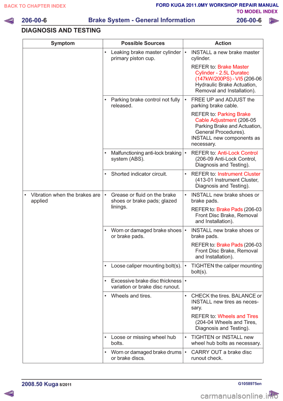
Action
Possible Sources
Symptom
• INSTALL a new brake mastercylinder.
REFER to: Brake Master
Cylinder - 2.5L Duratec
(147kW/200PS) - VI5 (206-06
Hydraulic Brake Actuation,
Removal and Installation).
• Leaking brake master cylinder
primary piston cup.
• FREE UP and ADJUST theparking brake cable.
REFER to: Parking Brake
Cable Adjustment (206-05
Parking Brake and Actuation,
General Procedures).
INSTALL new components as
necessary.
• Parking brake control not fully
released.
• REFER to:Anti-Lock Control
(206-09 Anti-Lock Control,
Diagnosis and Testing).
• Malfunctioning anti-lock braking
system (ABS).
• REFER to:Instrument Cluster
(413-01 Instrument Cluster,
Diagnosis and Testing).
• Shorted indicator circuit.
• INSTALL new brake shoes orbrake pads.
REFER to: Brake Pads (206-03
Front Disc Brake, Removal
and Installation).
• Grease or fluid on the brake
shoes or brake pads; glazed
linings.
• Vibration when the brakes are
applied
• INSTALL new brake shoes orbrake pads.
REFER to: Brake Pads (206-03
Front Disc Brake, Removal
and Installation).
• Worn or damaged brake shoes
or brake pads.
• TIGHTEN the caliper mountingbolt(s).
• Loose caliper mounting bolt(s).
•
• Excessive brake disc thickness
variation or brake disc runout.
• CHECK the tires. BALANCE orINSTALL new tires as neces-
sary.
REFER to: Wheels and Tires
(204-04 Wheels and Tires,
Diagnosis and Testing).
• Wheels and tires.
• TIGHTEN or INSTALL newwheel hub bolts as necessary.
• Loose or missing wheel hub
bolts.
• CARRY OUT a brake discrunout check.
• Worn or damaged brake drums
or brake discs.
G1058975en2008.50 Kuga8/2011
206-00- 6
Brake System - General Information
206-00- 6
DIAGNOSIS AND TESTING
TO MODEL INDEX
BACK TO CHAPTER INDEX
FORD KUGA 2011.0MY WORKSHOP REPAIR MANUAL
Page 1345 of 2057
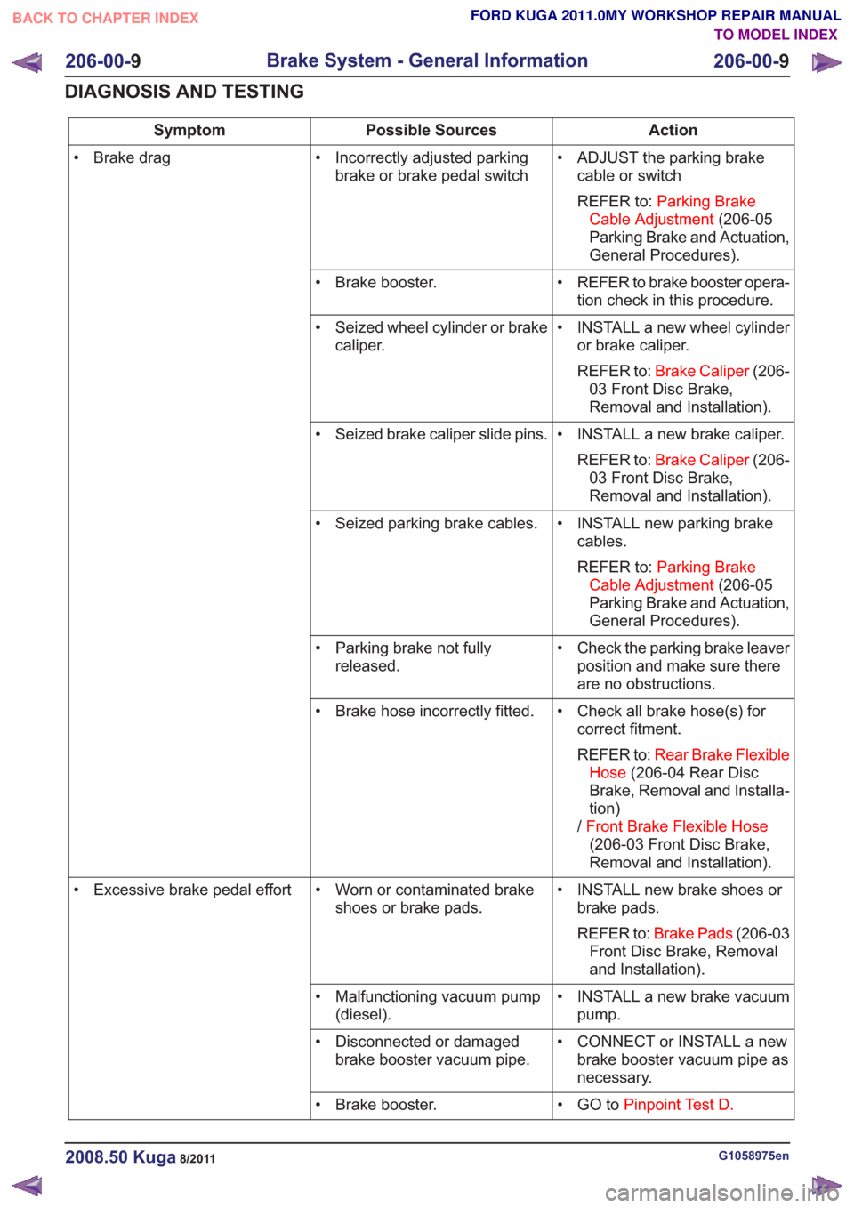
Action
Possible Sources
Symptom
• ADJUST the parking brakecable or switch
REFER to: Parking Brake
Cable Adjustment (206-05
Parking Brake and Actuation,
General Procedures).
• Incorrectly adjusted parking
brake or brake pedal switch
• Brake drag
• REFER to brake booster opera-tion check in this procedure.
• Brake booster.
• INSTALL a new wheel cylinderor brake caliper.
REFER to: Brake Caliper (206-
03 Front Disc Brake,
Removal and Installation).
• Seized wheel cylinder or brake
caliper.
• INSTALL a new brake caliper.REFER to: Brake Caliper (206-
03 Front Disc Brake,
Removal and Installation).
• Seized brake caliper slide pins.
• INSTALL new parking brakecables.
REFER to: Parking Brake
Cable Adjustment (206-05
Parking Brake and Actuation,
General Procedures).
• Seized parking brake cables.
• Check the parking brake leaverposition and make sure there
are no obstructions.
• Parking brake not fully
released.
• Check all brake hose(s) forcorrect fitment.
REFER to: Rear Brake Flexible
Hose (206-04 Rear Disc
Brake, Removal and Installa-
tion)
/ Front Brake Flexible Hose
(206-03 Front Disc Brake,
Removal and Installation).
• Brake hose incorrectly fitted.
• INSTALL new brake shoes orbrake pads.
REFER to: Brake Pads (206-03
Front Disc Brake, Removal
and Installation).
• Worn or contaminated brake
shoes or brake pads.
• Excessive brake pedal effort
• INSTALL a new brake vacuumpump.
• Malfunctioning vacuum pump
(diesel).
• CONNECT or INSTALL a newbrake booster vacuum pipe as
necessary.
• Disconnected or damaged
brake booster vacuum pipe.
• GO toPinpoint Test D.
• Brake booster.
G1058975en2008.50 Kuga8/2011
206-00- 9
Brake System - General Information
206-00- 9
DIAGNOSIS AND TESTING
TO MODEL INDEX
BACK TO CHAPTER INDEX
FORD KUGA 2011.0MY WORKSHOP REPAIR MANUAL
Page 1346 of 2057
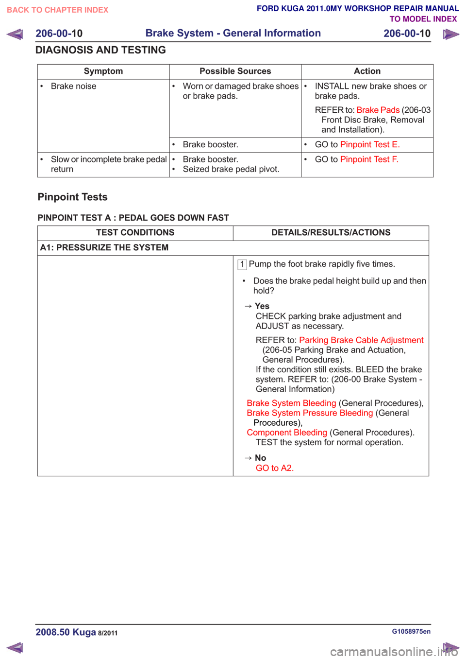
Action
Possible Sources
Symptom
• INSTALL new brake shoes orbrake pads.
REFER to: Brake Pads (206-03
Front Disc Brake, Removal
and Installation).
• Worn or damaged brake shoes
or brake pads.
• Brake noise
• GO toPinpoint Test E.
• Brake booster.
• GO toPinpoint Test F.
• Brake booster.
• Seized brake pedal pivot.
• Slow or incomplete brake pedal
return
Pinpoint Tests
PINPOINT TEST A : PEDAL GOES DOWN FAST
DETAILS/RESULTS/ACTIONS
TEST CONDITIONS
A1: PRESSURIZE THE SYSTEM
1 Pump the foot brake rapidly five times.
• Does the brake pedal height build up and then hold?
zYe s
CHECK parking brake adjustment and
ADJUST as necessary.
REFER to: Parking Brake Cable Adjustment
(206-05 Parking Brake and Actuation,
General Procedures).
If the condition still exists. BLEED the brake
system. REFER to: (206-00 Brake System -
General Information)
Brake System Bleeding (General Procedures),
Brake System Pressure Bleeding (General
Procedures),
Component Bleeding (General Procedures).
TEST the system for normal operation.
zNo
GO to A2.
G1058975en2008.50 Kuga8/2011
206-00- 10
Brake System - General Information
206-00- 10
DIAGNOSIS AND TESTING
TO MODEL INDEX
BACK TO CHAPTER INDEX
FORD KUGA 2011.0MY WORKSHOP REPAIR MANUAL
Page 1353 of 2057
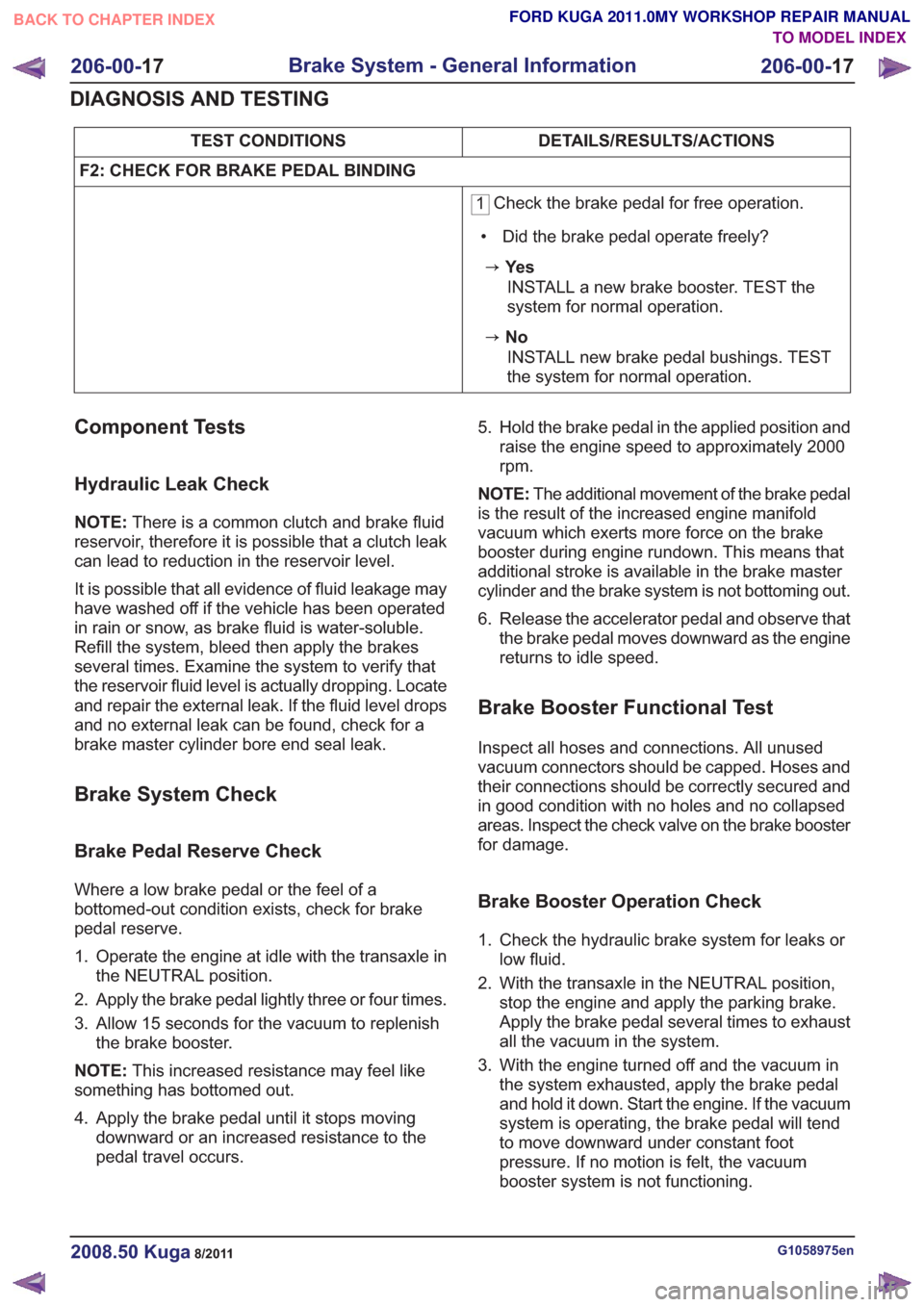
DETAILS/RESULTS/ACTIONS
TEST CONDITIONS
F2: CHECK FOR BRAKE PEDAL BINDING
1 Check the brake pedal for free operation.
• Did the brake pedal operate freely?
zYe s INSTALL a new brake booster. TEST the
system for normal operation.
zNoINSTALL new brake pedal bushings. TEST
the system for normal operation.
Component Tests
Hydraulic Leak Check
NOTE: There is a common clutch and brake fluid
reservoir, therefore it is possible that a clutch leak
can lead to reduction in the reservoir level.
It is possible that all evidence of fluid leakage may
have washed off if the vehicle has been operated
in rain or snow, as brake fluid is water-soluble.
Refill the system, bleed then apply the brakes
several times. Examine the system to verify that
the reservoir fluid level is actually dropping. Locate
and repair the external leak. If the fluid level drops
and no external leak can be found, check for a
brake master cylinder bore end seal leak.
Brake System Check
Brake Pedal Reserve Check
Where a low brake pedal or the feel of a
bottomed-out condition exists, check for brake
pedal reserve.
1. Operate the engine at idle with the transaxle in the NEUTRAL position.
2. Apply the brake pedal lightly three or four times.
3. Allow 15 seconds for the vacuum to replenish the brake booster.
NOTE: This increased resistance may feel like
something has bottomed out.
4. Apply the brake pedal until it stops moving downward or an increased resistance to the
pedal travel occurs. 5. Hold the brake pedal in the applied position and
raise the engine speed to approximately 2000
rpm.
NOTE: The additional movement of the brake pedal
is the result of the increased engine manifold
vacuum which exerts more force on the brake
booster during engine rundown. This means that
additional stroke is available in the brake master
cylinder and the brake system is not bottoming out.
6. Release the accelerator pedal and observe that the brake pedal moves downward as the engine
returns to idle speed.
Brake Booster Functional Test
Inspect all hoses and connections. All unused
vacuum connectors should be capped. Hoses and
their connections should be correctly secured and
in good condition with no holes and no collapsed
areas. Inspect the check valve on the brake booster
for damage.
Brake Booster Operation Check
1. Check the hydraulic brake system for leaks orlow fluid.
2. With the transaxle in the NEUTRAL position, stop the engine and apply the parking brake.
Apply the brake pedal several times to exhaust
all the vacuum in the system.
3. With the engine turned off and the vacuum in the system exhausted, apply the brake pedal
and hold it down. Start the engine. If the vacuum
system is operating, the brake pedal will tend
to move downward under constant foot
pressure. If no motion is felt, the vacuum
booster system is not functioning.
G1058975en2008.50 Kuga8/2011
206-00- 17
Brake System - General Information
206-00- 17
DIAGNOSIS AND TESTING
TO MODEL INDEX
BACK TO CHAPTER INDEX
FORD KUGA 2011.0MY WORKSHOP REPAIR MANUAL
Page 1354 of 2057
4. Remove the vacuum hose from the brakebooster. Manifold vacuum should be available
at the brake booster end of the hose with the
engine at idle speed and the transaxle in the
NEUTRAL position. Make sure that all unused
vacuum outlets are correctly capped, hose
connectors are correctly secured and vacuum
hoses are in good condition. When it is
established that manifold vacuum is available
to the brake booster, connect the vacuum hose
to the brake booster and repeat Step 3. If no
downward movement of the brake pedal is felt,
install a new brake booster.
5. Operate the engine a minimum of 10 seconds at approximately 1200 rpm. Stop the engine and
let the vehicle stand for 10 minutes. Then, apply
the brake pedal with approximately 89 N (20 lb)
force. The pedal feel (brake application) should
be the same as that noted with the engine
operating. If the brake pedal feels hard (no
power assist), install a new vacuum check valve
and then repeat the test. If the brake pedal still
feels hard, install a new brake booster. If the
brake pedal movement feels spongy, bleed the
brake system. REFER to: (206-00 Brake System
- General Information)
Brake System Bleeding (General Procedures),
Brake System Pressure Bleeding (General
Procedures),
Component Bleeding (General Procedures).
Brake Master Cylinder
Usually, the first and strongest indicator of anything
wrong with the braking system is a feeling through
the brake pedal. In diagnosing the condition of the
brake master cylinder, check pedal feel as
evidence of a brake concern. Check for the red
brake warning indicator illumination and the fluid
level in the master cylinder reservoir.
Normal Conditions
The following conditions are considered normal
and are not indications that the brake master
cylinder is in need of service.
– Modern brake systems are not designed to
produce as hard a pedal effort as in the past.
Complaints of light pedal efforts should be compared to pedal efforts of another vehicle, of
the same model and year.
– During normal operation of the brake pedal, the fluid level in the reservoir will rise during brake
pedal application and fall during release. The
net fluid level (i.e., after brake pedal application
and release) will remain unchanged.
– A trace of brake fluid will exists on the brake booster shell below the master cylinder
mounting flange. This results from the normal
lubricating action of the master cylinder bore
end seal.
– The fluid level will fall with brake shoe and lining wear.
Abnormal Conditions
NOTE: Prior to performing any diagnosis, make
sure the brake system warning indicator is
functional.
Changes in brake pedal feel or travel are indicators
that something could be wrong with the braking
system. The diagnostic procedure and techniques
use brake pedal feel, warning indicator illumination
and low brake fluid level as indicators in diagnosing
braking system concerns. The following conditions
are considered abnormal and indicate that the
brake master cylinder is in need of service.
– The brake pedal goes down fast. This could be caused by an external or internal leak.
– The brake pedal eases down slowly. This could be caused by an external or internal leak.
– The brake pedal is low and or feels spongy. This condition may be caused by no fluid in the brake
master cylinder reservoir, reservoir cap vent
holes clogged or air in the hydraulic system.
– The brake pedal effort is excessive. This may be caused by a bind or obstruction in the pedal
or linkage, clogged fluid control valve or
insufficient booster vacuum.
– The rear brakes lock up during light pedal force. This may be caused by incorrect tire pressures,
grease or fluid on the brake shoes and linings,
damaged brake shoes and linings, incorrectly
adjusted parking brake, or damaged or
contaminated brake pressure control valves.
– The brake pedal effort is erratic. This condition could be caused by a brake booster malfunction,
extreme caliper piston knock back or incorrectly
installed brake shoes and linings.
– The red brake warning indicator is ON. This may be caused by low fluid level, ignition wire routing
G1058975en2008.50 Kuga8/2011
206-00- 18
Brake System - General Information
206-00- 18
DIAGNOSIS AND TESTING
TO MODEL INDEX
BACK TO CHAPTER INDEX
FORD KUGA 2011.0MY WORKSHOP REPAIR MANUAL
Page 1384 of 2057
SECTION 206-05 Parking Brake and Actuation
VEHICLE APPLICATION:2008.50 Kuga
PA G E
CONTENTS
DESCRIPTION AND OPERATION
206-05-2
Parking Brake (Overview) ........................................................................\
...........................
206-05-2
Overview ........................................................................\
.....................................................
206-05-2
Parking brake cable ........................................................................\
....................................
206-05-3
Parking brake control ........................................................................\
..................................
DIAGNOSIS AND TESTING 206-05-4
Parking Brake ........................................................................\
.............................................
206-05-4
Inspection and Verification ........................................................................\
..........................
206-05-4
Symptom Chart ........................................................................\
...........................................
206-05-5
Pinpoint Tests ........................................................................\
.............................................
GENERAL PROCEDURES 206-05-9
Parking Brake Cable Adjustment ........................................................................\
................
REMOVAL AND INSTALLATION 206-05-11
(12 664 0)
Parking Brake Control ........................................................................\
............
206-05-12
Parking Brake Rear Cables ........................................................................\
........................
206-05-1
Parking Brake and Actuation
206-05- 1
.
TO MODEL INDEX
BACK TO CHAPTER INDEX
FORD KUGA 2011.0MY WORKSHOP REPAIR MANUAL
Page 1385 of 2057
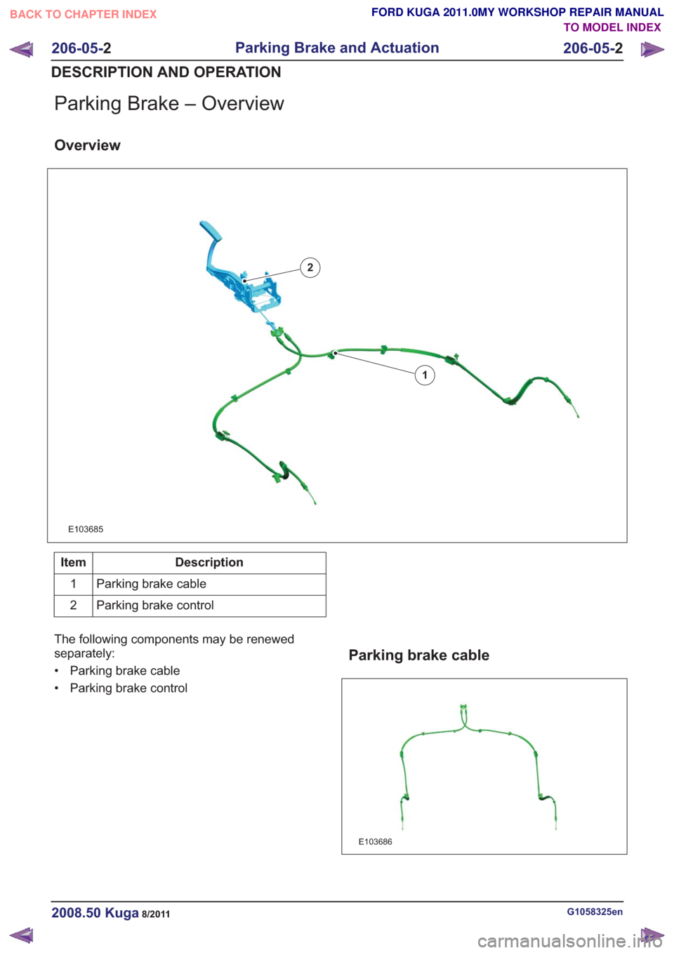
Parking Brake – Overview
Overview
E103685
1
2
Description
Item
Parking brake cable
1
Parking brake control
2
The following components may be renewed
separately:
• Parking brake cable
• Parking brake control
Parking brake cable
E103686
G1058325en2008.50 Kuga8/2011
206-05- 2
Parking Brake and Actuation
206-05- 2
DESCRIPTION AND OPERATION
TO MODEL INDEX
BACK TO CHAPTER INDEX
FORD KUGA 2011.0MY WORKSHOP REPAIR MANUAL
Page 1386 of 2057
The following instructions must be followed when
removing, installing or renewing the parking brake
cable:
• If the parking brake cable is removed, installedor renewed, the parking brake must be adjusted
after the work is completed.
Refer to: Parking Brake Cable Adjustment
(206-05 Parking Brake and Actuation, General
Procedures).
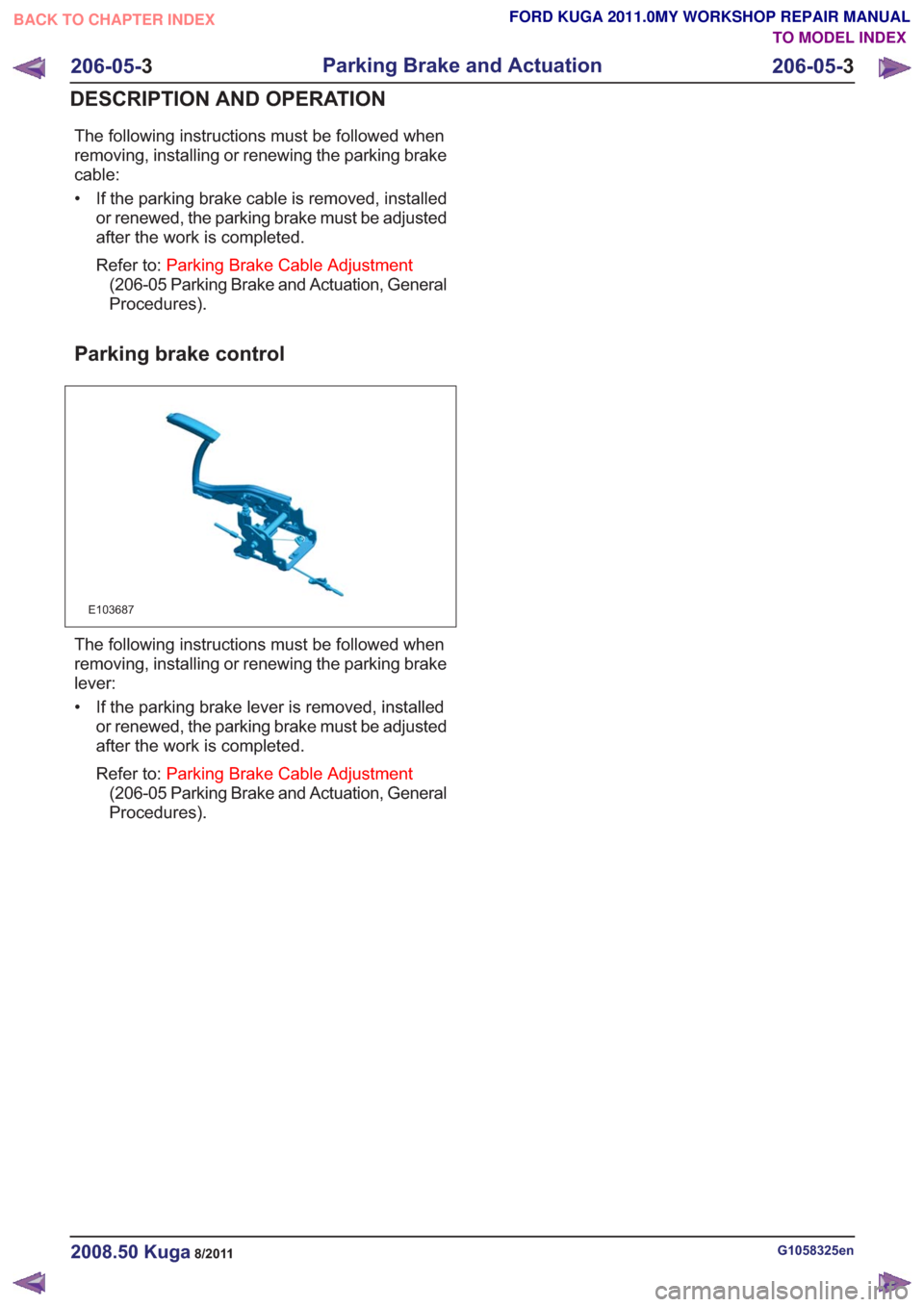
Parking brake control
E103687
The following instructions must be followed when
removing, installing or renewing the parking brake
lever:
• If the parking brake lever is removed, installed or renewed, the parking brake must be adjusted
after the work is completed.
Refer to: Parking Brake Cable Adjustment
(206-05 Parking Brake and Actuation, General
Procedures).
G1058325en2008.50 Kuga8/2011
206-05- 3
Parking Brake and Actuation
206-05- 3
DESCRIPTION AND OPERATION
TO MODEL INDEX
BACK TO CHAPTER INDEX
FORD KUGA 2011.0MY WORKSHOP REPAIR MANUAL