Page 1395 of 2057
Parking Brake Rear Cables
Removal
NOTE:Removal steps in this procedure may
contain installation details.
1. Fully release the parking brake control.
2.
E92650
3. Loosen the parking brake cable adjustment nut
to the end of the parking brake cable thread.
E92651
4.Refer to: Wheel and Tire (204-04 Wheels and
Tires, Removal and Installation).
4x4
5. Torque: 25Nm
E101187
x2
x4
1
2
3
4x2
6.Torque: 25Nm
E101189
x4
G1072319en2008.50 Kuga8/2011
206-05- 12
Parking Brake and Actuation
206-05- 12
REMOVAL AND INSTALLATION
TO MODEL INDEX
BACK TO CHAPTER INDEX
FORD KUGA 2011.0MY WORKSHOP REPAIR MANUAL
Page 1396 of 2057
All vehicles
7.Torque: 25Nm1.
2. Torque: 5
Nm
E101191
1
x4
2
3
8.Torque: 5Nm
E101190
x4
9.
E101192
1
2
x2
10.
E70349
2
43
1
11 .Torque: 2Nm
G1072319en2008.50 Kuga8/2011
206-05- 13
Parking Brake and Actuation
206-05- 13
REMOVAL AND INSTALLATION
TO MODEL INDEX
BACK TO CHAPTER INDEX
FORD KUGA 2011.0MY WORKSHOP REPAIR MANUAL
Page 1397 of 2057
E101193
1
x43
2
Installation
1.To install, reverse the removal procedure.
2. Refer to: Parking Brake Cable Adjustment
(206-05 Parking Brake and Actuation, General
Procedures).
G1072319en2008.50 Kuga8/2011
206-05- 14
Parking Brake and Actuation
206-05- 14
REMOVAL AND INSTALLATION
BACK TO CHAPTER INDEXFORD KUGA 2011.0MY WORKSHOP REPAIR MANUAL
TO MODEL INDEX
Page 1445 of 2057

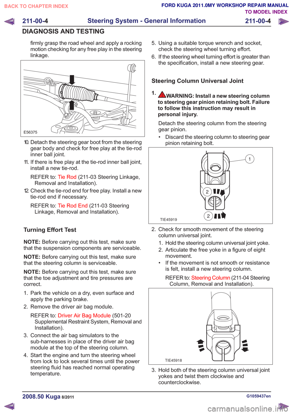
firmly grasp the road wheel and apply a rocking
motion checking for any free play in the steering
linkage.
E56375
10. Detach the steering gear boot from the steeringgear body and check for free play at the tie-rod
inner ball joint.
11. If there is free play at the tie-rod inner ball joint, install a new tie-rod.
REFER to: Tie Rod(211-03 Steering Linkage,
Removal and Installation).
12. Check the tie-rod end for free play. Install a new tie-rod end if necessary.
REFER to: Tie Rod End (211-03 Steering
Linkage, Removal and Installation).
Turning Effort Test
NOTE: Before carrying out this test, make sure
that the suspension components are serviceable.
NOTE: Before carrying out this test, make sure
that the steering column is serviceable.
NOTE: Before carrying out this test, make sure
that the toe adjustment and tire pressures are
correct.
1. Park the vehicle on a dry, even surface and apply the parking brake.
2. Remove the driver air bag module.
REFER to: Driver Air Bag Module (501-20
Supplemental Restraint System, Removal and
Installation).
3. Connect the air bag simulators to the sub-harnesses in place of the driver air bag
module at the top of the steering column.
4. Start the engine and turn the steering wheel from lock to lock several times until the power
steering fluid has reached normal operating
temperature. 5. Using a suitable torque wrench and socket,
check the steering wheel turning effort.
6. If the steering wheel turning effort is greater than the specification, install a new steering gear.
Steering Column Universal Joint
1.WARNING: Install a new steering column
to steering gear pinion retaining bolt. Failure
to follow this instruction may result in
personal injury.
Detach the steering column from the steering
gear pinion.• Discard the steering column to steering gear pinion retaining bolt.
TIE45919
1
2
2
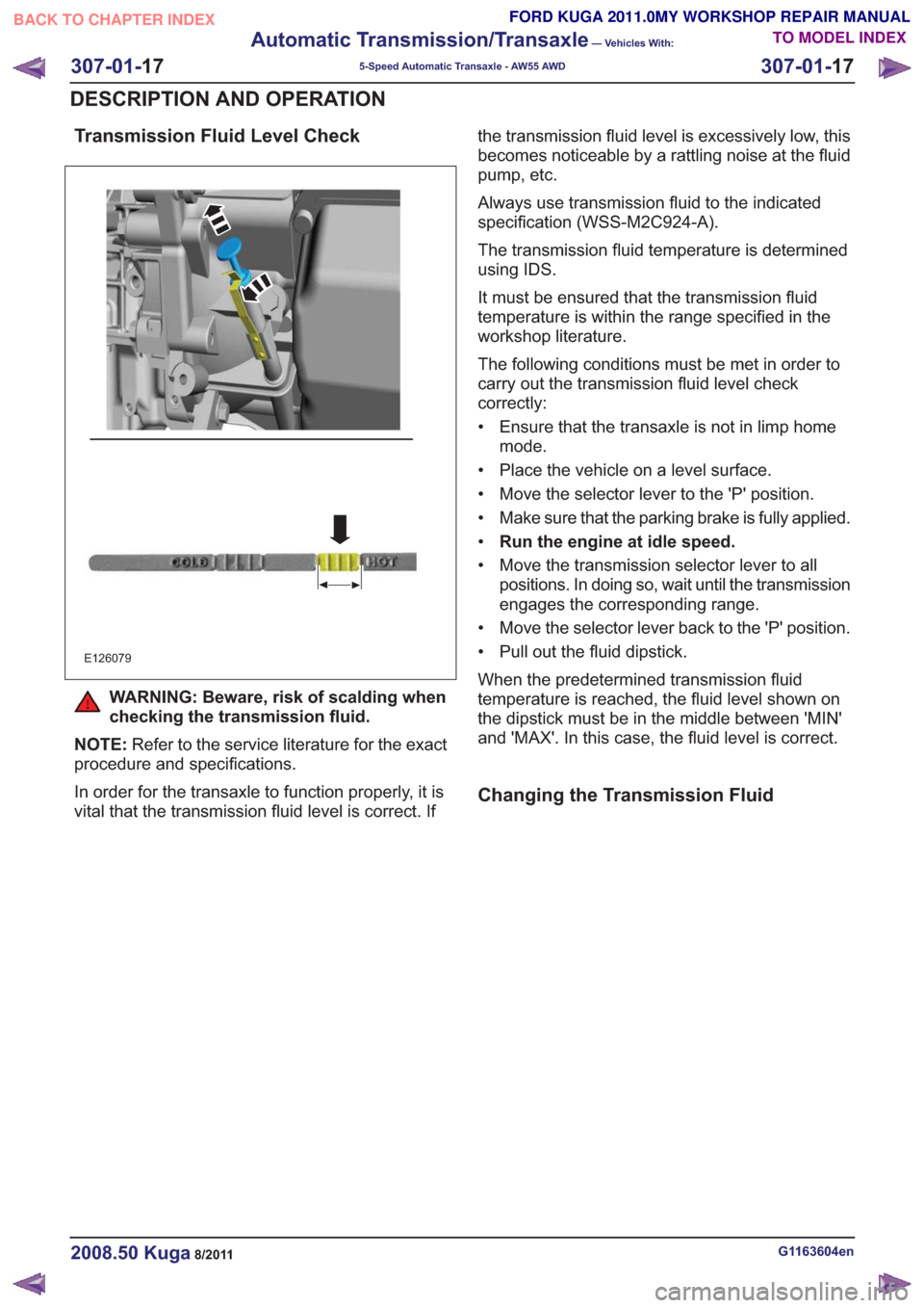
2. Check for smooth movement of the steeringcolumn universal joint.
1. Hold the steering column universal joint yoke.
2. Articulate the free yoke in a figure of eight movement.
• If the movement is not smooth or resistance is felt, install a new steering column.
REFER to: Steering Column (211-04 Steering
Column, Removal and Installation).
TIE45918
3. Hold both of the steering column universal joint yokes and twist them clockwise and
counterclockwise.
G1059437en2008.50 Kuga8/2011
211-00- 4
Steering System - General Information
211-00- 4
DIAGNOSIS AND TESTING
TO MODEL INDEX
BACK TO CHAPTER INDEX
FORD KUGA 2011.0MY WORKSHOP REPAIR MANUAL
Page 1838 of 2057

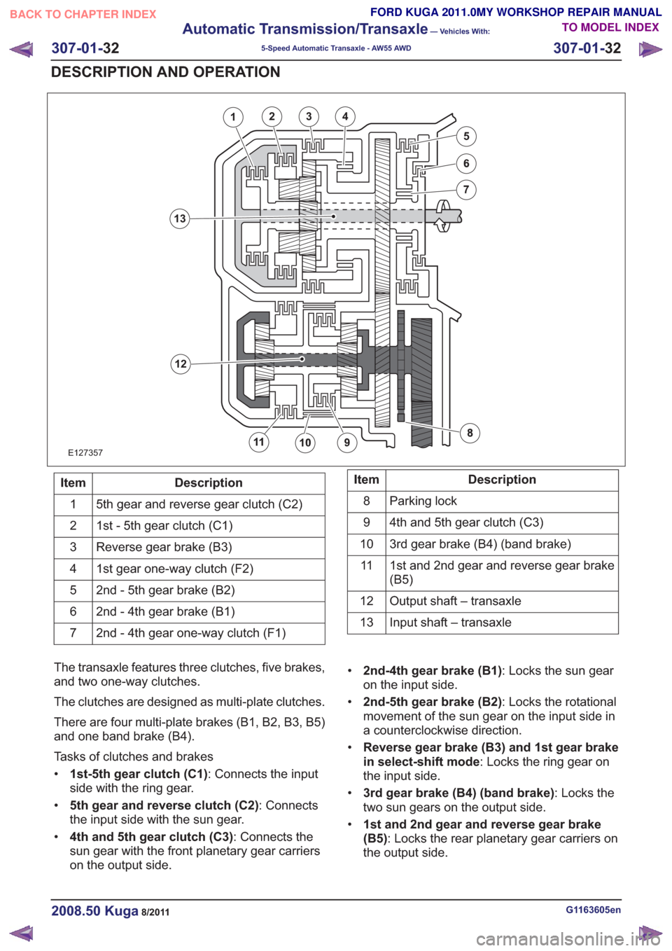
Transmission Fluid Level Check
E126079
WARNING: Beware, risk of scalding when
checking the transmission fluid.
NOTE: Refer to the service literature for the exact
procedure and specifications.
In order for the transaxle to function properly, it is
vital that the transmission fluid level is correct. If the transmission fluid level is excessively low, this
becomes noticeable by a rattling noise at the fluid
pump, etc.
Always use transmission fluid to the indicated
specification (WSS-M2C924-A).
The transmission fluid temperature is determined
using IDS.
It must be ensured that the transmission fluid
temperature is within the range specified in the
workshop literature.
The following conditions must be met in order to
carry out the transmission fluid level check
correctly:
• Ensure that the transaxle is not in limp home
mode.
• Place the vehicle on a level surface.
• Move the selector lever to the 'P' position.
• Make sure that the parking brake is fully applied.
• Run the engine at idle speed.
• Move the transmission selector lever to all positions. In doing so, wait until the transmission
engages the corresponding range.
• Move the selector lever back to the 'P' position.
• Pull out the fluid dipstick.
When the predetermined transmission fluid
temperature is reached, the fluid level shown on
the dipstick must be in the middle between 'MIN'
and 'MAX'. In this case, the fluid level is correct.
Changing the Transmission Fluid
G1163604en2008.50 Kuga8/2011
307-01- 17
Automatic Transmission/Transaxle
— Vehicles With:
5-Speed Automatic Transaxle - AW55 AWD
307-01- 17
DESCRIPTION AND OPERATION
TO MODEL INDEX
BACK TO CHAPTER INDEX
FORD KUGA 2011.0MY WORKSHOP REPAIR MANUAL
Page 1853 of 2057

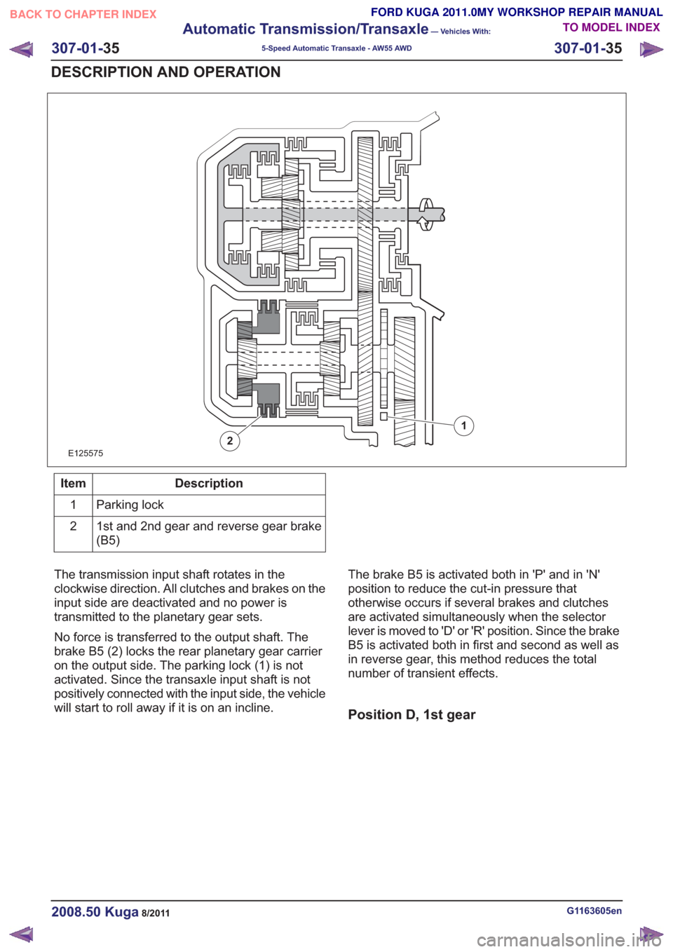
E127357
1234
5
12
13
Description
Item
5th gear and reverse gear clutch (C2)
1
1st - 5th gear clutch (C1)
2
Reverse gear brake (B3)
3
1st gear one-way clutch (F2)
4
2nd - 5th gear brake (B2)
5
2nd - 4th gear brake (B1)
6
2nd - 4th gear one-way clutch (F1)
7Description
Item
Parking lock
8
4th and 5th gear clutch (C3)
9
3rd gear brake (B4) (band brake)
10
1st and 2nd gear and reverse gear brake
(B5)
11
Output shaft – transaxle
12
Input shaft – transaxle
13
The transaxle features three clutches, five brakes,
and two one-way clutches.
The clutches are designed as multi-plate clutches.
There are four multi-plate brakes (B1, B2, B3, B5)
and one band brake (B4).
Tasks of clutches and brakes
• 1st-5th gear clutch (C1) : Connects the input
side with the ring gear.
• 5th gear and reverse clutch (C2) : Connects
the input side with the sun gear.
• 4th and 5th gear clutch (C3) : Connects the
sun gear with the front planetary gear carriers
on the output side. •
2nd-4th gear brake (B1) : Locks the sun gear
on the input side.
• 2nd-5th gear brake (B2) : Locks the rotational
movement of the sun gear on the input side in
a counterclockwise direction.
• Reverse gear brake (B3) and 1st gear brake
in select-shift mode : Locks the ring gear on
the input side.
• 3rd gear brake (B4) (band brake) : Locks the
two sun gears on the output side.
• 1st and 2nd gear and reverse gear brake
(B5) : Locks the rear planetary gear carriers on
the output side.
G1163605en2008.50 Kuga8/2011
307-01- 32
Automatic Transmission/Transaxle
— Vehicles With:
5-Speed Automatic Transaxle - AW55 AWD
307-01- 32
DESCRIPTION AND OPERATION
TO MODEL INDEX
BACK TO CHAPTER INDEX
FORD KUGA 2011.0MY WORKSHOP REPAIR MANUAL
Page 1855 of 2057
E125574
12
Description
Item
1st and 2nd gear and reverse gear brake
(B5)
1
Parking lock
2
The transmission input shaft rotates in the
clockwise direction. All clutches and brakes are
deactivated and no force is transferred to the
planetary gear sets.
No force is transferred to the output shaft. The
brake B5 (1) locks the rear planetary gear carrier on the output side. The parking lock (2) engages
in the output shaft and stops the vehicle rolling
away.
Position N (neutral)
G1163605en2008.50 Kuga8/2011
307-01-
34
Automatic Transmission/Transaxle
— Vehicles With:
5-Speed Automatic Transaxle - AW55 AWD
307-01- 34
DESCRIPTION AND OPERATION
TO MODEL INDEX
BACK TO CHAPTER INDEX
FORD KUGA 2011.0MY WORKSHOP REPAIR MANUAL
Page 1856 of 2057

E125575
1
2
Description
Item
Parking lock
1
1st and 2nd gear and reverse gear brake
(B5)
2
The transmission input shaft rotates in the
clockwise direction. All clutches and brakes on the
input side are deactivated and no power is
transmitted to the planetary gear sets.
No force is transferred to the output shaft. The
brake B5 (2) locks the rear planetary gear carrier
on the output side. The parking lock (1) is not
activated. Since the transaxle input shaft is not
positively connected with the input side, the vehicle
will start to roll away if it is on an incline. The brake B5 is activated both in 'P' and in 'N'
position to reduce the cut-in pressure that
otherwise occurs if several brakes and clutches
are activated simultaneously when the selector
lever is moved to 'D' or 'R' position. Since the brake
B5 is activated both in first and second as well as
in reverse gear, this method reduces the total
number of transient effects.
Position D, 1st gear
G1163605en2008.50 Kuga8/2011
307-01-
35
Automatic Transmission/Transaxle
— Vehicles With:
5-Speed Automatic Transaxle - AW55 AWD
307-01- 35
DESCRIPTION AND OPERATION
TO MODEL INDEX
BACK TO CHAPTER INDEX
FORD KUGA 2011.0MY WORKSHOP REPAIR MANUAL