2011 FORD KUGA bus
[x] Cancel search: busPage 1277 of 2057
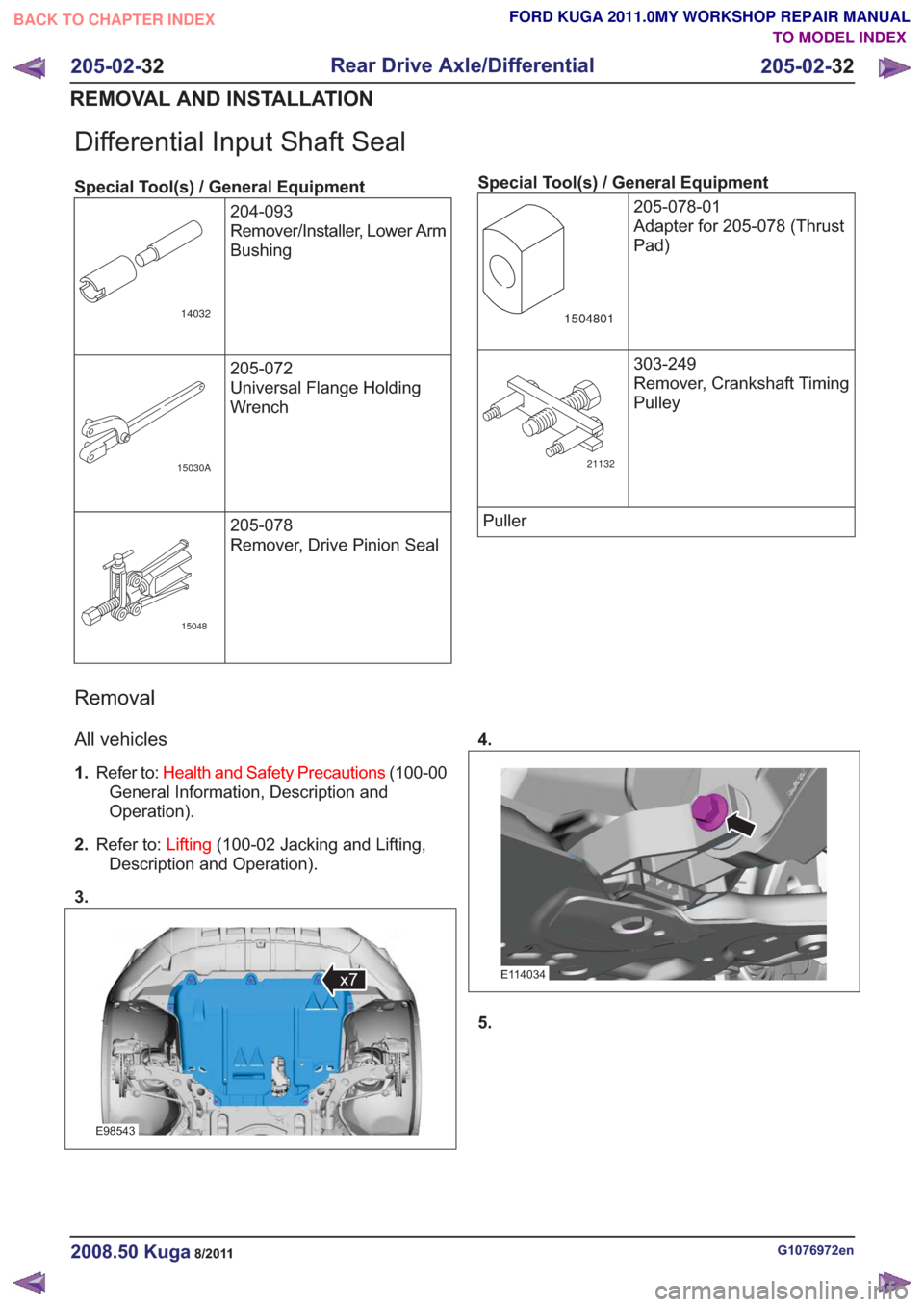
Differential Input Shaft Seal
Special Tool(s) / General Equipment204-093
Remover/Installer, Lower Arm
Bushing
14032
205-072
Universal Flange Holding
Wrench
15030A
205-078
Remover, Drive Pinion Seal
15048
Special Tool(s) / General Equipment205-078-01
Adapter for 205-078 (Thrust
Pad)
1504801
303-249
Remover, Crankshaft Timing
Pulley
21132
Puller
Removal
All vehicles
1.Refer to: Health and Safety Precautions (100-00
General Information, Description and
Operation).
2. Refer to: Lifting(100-02 Jacking and Lifting,
Description and Operation).
3.
E98543
x7
4.
E114034
5.
G1076972en2008.50 Kuga8/2011
205-02- 32
Rear Drive Axle/Differential
205-02- 32
REMOVAL AND INSTALLATION
TO MODEL INDEX
BACK TO CHAPTER INDEX
FORD KUGA 2011.0MY WORKSHOP REPAIR MANUAL
Page 1283 of 2057
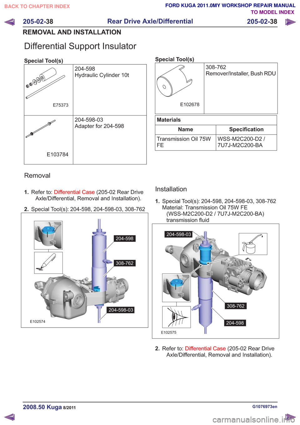
Differential Support Insulator
Special Tool(s)204-598
Hydraulic Cylinder 10t
E75373
204-598-03
Adapter for 204-598
E103784
Special Tool(s)308-762
Remover/Installer, Bush RDU
E102678
Materials
Specification
Name
WSS-M2C200-D2 /
7U7J-M2C200-BA
Transmission Oil 75W
FE
Removal
1.
Refer to: Differential Case (205-02 Rear Drive
Axle/Differential, Removal and Installation).
2. Special Tool(s): 204-598, 204-598-03, 308-762
308-762
204-598
204-598-03
308-762
204-598
204-598-03
E102574
Installation
1.Special Tool(s): 204-598, 204-598-03, 308-762
Material: Transmission Oil 75W FE
(WSS-M2C200-D2 / 7U7J-M2C200-BA)
transmission fluid
308-762
204-598
204-598-03
308-762
204-598
204-598-03
E102575
2. Refer to: Differential Case (205-02 Rear Drive
Axle/Differential, Removal and Installation).
G1076973en2008.50 Kuga8/2011
205-02- 38
Rear Drive Axle/Differential
205-02- 38
REMOVAL AND INSTALLATION
TO MODEL INDEX
BACK TO CHAPTER INDEX
FORD KUGA 2011.0MY WORKSHOP REPAIR MANUAL
Page 1299 of 2057
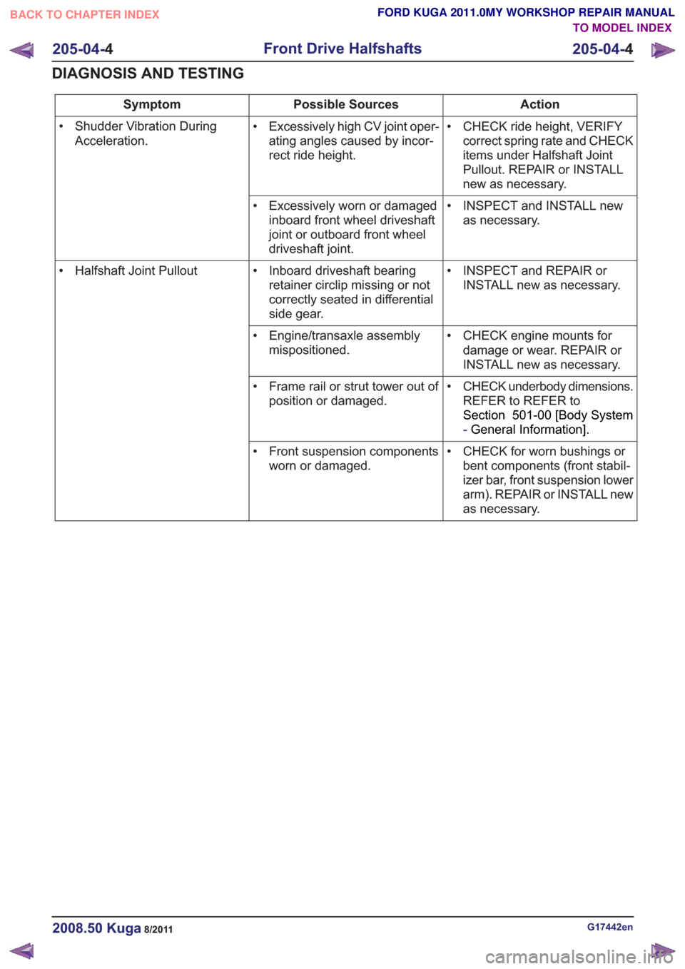
Action
Possible Sources
Symptom
• CHECK ride height, VERIFYcorrect spring rate and CHECK
items under Halfshaft Joint
Pullout. REPAIR or INSTALL
new as necessary.
• Excessively high CV joint oper-
ating angles caused by incor-
rect ride height.
• Shudder Vibration During
Acceleration.
• INSPECT and INSTALL newas necessary.
• Excessively worn or damaged
inboard front wheel driveshaft
joint or outboard front wheel
driveshaft joint.
• INSPECT and REPAIR orINSTALL new as necessary.
• Inboard driveshaft bearing
retainer circlip missing or not
correctly seated in differential
side gear.
• Halfshaft Joint Pullout
• CHECK engine mounts fordamage or wear. REPAIR or
INSTALL new as necessary.
• Engine/transaxle assembly
mispositioned.
• CHECK underbody dimensions.REFER to REFER to
Section 501-00 [Body System
-General Information] .
• Frame rail or strut tower out of
position or damaged.
• CHECK for worn bushings orbent components (front stabil-
izer bar, front suspension lower
arm). REPAIR or INSTALL new
as necessary.
• Front suspension components
worn or damaged.
G17442en2008.50 Kuga8/2011
205-04- 4
Front Drive Halfshafts
205-04- 4
DIAGNOSIS AND TESTING
TO MODEL INDEX
BACK TO CHAPTER INDEX
FORD KUGA 2011.0MY WORKSHOP REPAIR MANUAL
Page 1322 of 2057
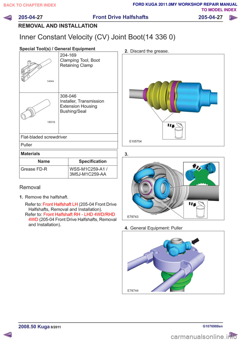
Inner Constant Velocity (CV) Joint Boot(14 336 0)
Special Tool(s) / General Equipment204-169
Clamping Tool, Boot
Retaining Clamp
14044
308-046
Installer, Transmission
Extension Housing
Bushing/Seal
16016
Flat-bladed screwdriver
Puller
Materials
Specification
Name
WSS-M1C259-A1 /
3M5J-M1C259-AA
Grease FD-R
Removal
1.
Remove the halfshaft.
Refer to: Front Halfshaft LH (205-04 Front Drive
Halfshafts, Removal and Installation).
Refer to: Front Halfshaft RH - LHD 4WD/RHD
4WD (205-04 Front Drive Halfshafts, Removal
and Installation). 2.
Discard the grease.
E105704
3.
E78743
4.General Equipment: Puller
E78744
G1076988en2008.50 Kuga8/2011
205-04- 27
Front Drive Halfshafts
205-04- 27
REMOVAL AND INSTALLATION
TO MODEL INDEX
BACK TO CHAPTER INDEX
FORD KUGA 2011.0MY WORKSHOP REPAIR MANUAL
Page 1350 of 2057
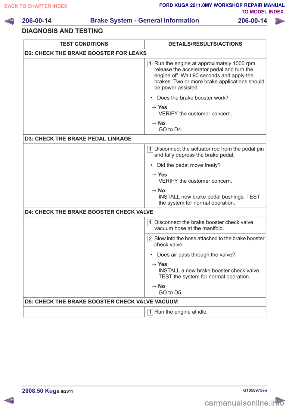
DETAILS/RESULTS/ACTIONS
TEST CONDITIONS
D2: CHECK THE BRAKE BOOSTER FOR LEAKS
1 Run the engine at approximately 1000 rpm,
release the accelerator pedal and turn the
engine off. Wait 90 seconds and apply the
brakes. Two or more brake applications should
be power assisted.
• Does the brake booster work?
zYe s VERIFY the customer concern.
zNoGO to D4 .
D3: CHECK THE BRAKE PEDAL LINKAGE
1 Disconnect the actuator rod from the pedal pin
and fully depress the brake pedal.
• Did the pedal move freely?
zYe s VERIFY the customer concern.
zNoINSTALL new brake pedal bushings. TEST
the system for normal operation.
D4: CHECK THE BRAKE BOOSTER CHECK VALVE
1 Disconnect the brake booster check valve
vacuum hose at the manifold.
2Blow into the hose attached to the brake booster
check valve.
• Does air pass through the valve?
zYe s INSTALL a new brake booster check valve.
TEST the system for normal operation.
zNoGO to D5 .
D5: CHECK THE BRAKE BOOSTER CHECK VALVE VACUUM
1 Run the engine at idle.
G1058975en2008.50 Kuga8/2011
206-00-
14
Brake System - General Information
206-00- 14
DIAGNOSIS AND TESTING
TO MODEL INDEX
BACK TO CHAPTER INDEX
FORD KUGA 2011.0MY WORKSHOP REPAIR MANUAL
Page 1353 of 2057
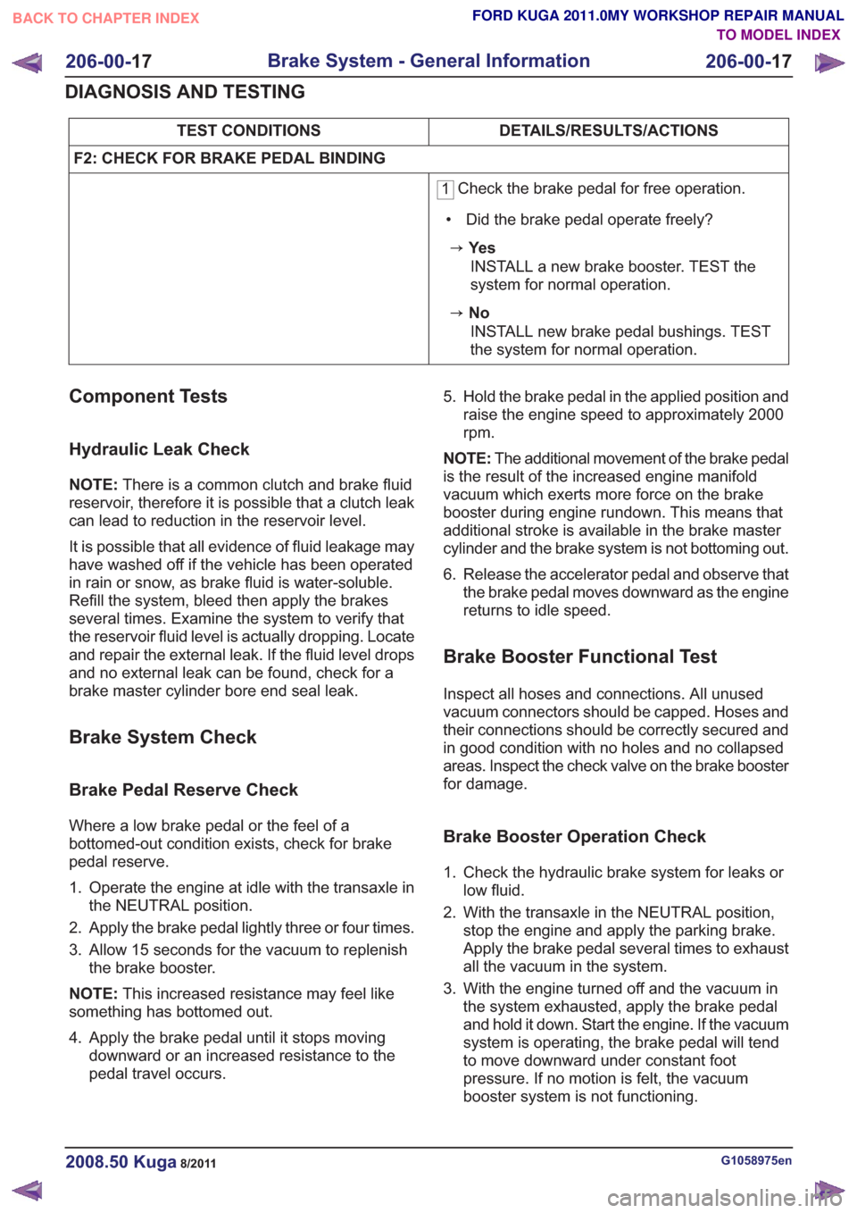
DETAILS/RESULTS/ACTIONS
TEST CONDITIONS
F2: CHECK FOR BRAKE PEDAL BINDING
1 Check the brake pedal for free operation.
• Did the brake pedal operate freely?
zYe s INSTALL a new brake booster. TEST the
system for normal operation.
zNoINSTALL new brake pedal bushings. TEST
the system for normal operation.
Component Tests
Hydraulic Leak Check
NOTE: There is a common clutch and brake fluid
reservoir, therefore it is possible that a clutch leak
can lead to reduction in the reservoir level.
It is possible that all evidence of fluid leakage may
have washed off if the vehicle has been operated
in rain or snow, as brake fluid is water-soluble.
Refill the system, bleed then apply the brakes
several times. Examine the system to verify that
the reservoir fluid level is actually dropping. Locate
and repair the external leak. If the fluid level drops
and no external leak can be found, check for a
brake master cylinder bore end seal leak.
Brake System Check
Brake Pedal Reserve Check
Where a low brake pedal or the feel of a
bottomed-out condition exists, check for brake
pedal reserve.
1. Operate the engine at idle with the transaxle in the NEUTRAL position.
2. Apply the brake pedal lightly three or four times.
3. Allow 15 seconds for the vacuum to replenish the brake booster.
NOTE: This increased resistance may feel like
something has bottomed out.
4. Apply the brake pedal until it stops moving downward or an increased resistance to the
pedal travel occurs. 5. Hold the brake pedal in the applied position and
raise the engine speed to approximately 2000
rpm.
NOTE: The additional movement of the brake pedal
is the result of the increased engine manifold
vacuum which exerts more force on the brake
booster during engine rundown. This means that
additional stroke is available in the brake master
cylinder and the brake system is not bottoming out.
6. Release the accelerator pedal and observe that the brake pedal moves downward as the engine
returns to idle speed.
Brake Booster Functional Test
Inspect all hoses and connections. All unused
vacuum connectors should be capped. Hoses and
their connections should be correctly secured and
in good condition with no holes and no collapsed
areas. Inspect the check valve on the brake booster
for damage.
Brake Booster Operation Check
1. Check the hydraulic brake system for leaks orlow fluid.
2. With the transaxle in the NEUTRAL position, stop the engine and apply the parking brake.
Apply the brake pedal several times to exhaust
all the vacuum in the system.
3. With the engine turned off and the vacuum in the system exhausted, apply the brake pedal
and hold it down. Start the engine. If the vacuum
system is operating, the brake pedal will tend
to move downward under constant foot
pressure. If no motion is felt, the vacuum
booster system is not functioning.
G1058975en2008.50 Kuga8/2011
206-00- 17
Brake System - General Information
206-00- 17
DIAGNOSIS AND TESTING
TO MODEL INDEX
BACK TO CHAPTER INDEX
FORD KUGA 2011.0MY WORKSHOP REPAIR MANUAL
Page 1429 of 2057
HCU to check for sudden actuation of the brakes.
With the brake pedal pressed, the ABS module
triggers emergency braking if the rate of increase
of hydraulic pressure exceeds the predetermined
limit.
If the brake pedal is pressed so hard that the ABS
becomes active on the front wheels then the ABS
control unit increases the pressure to the rear
wheel brakes up to the ABS intervention threshold.
EBA operation continues until the driver releases
the brake pedal sufficiently for the hydraulic
pressure in the HCU to drop below a threshold
value stored in the ABS module.
Trailer stability control:If the vehicle is ordered
with a trailer coupling then the Trailer Stability
Control function is integrated in the ESP. The ESP
detects snaking when driving with a trailer and
reduces the speed of the vehicle and trailer through
adapted braking and, if necessary, by also reducing
the engine output until the snaking movement of
the trailer is corrected.
Roll-over protection: The ESP dynamically
determines the tipping tendency of the vehicle and
works in conjunction with the EBA system to
prevent the vehicle from tipping over during
dynamic maneuvers like lane changing or while
negotiating bends.
Emergency brake light: The emergency brake
light automatically switches on the hazard flasher
system to warn drivers of other vehicles that
emergency braking is being initiated. Based on a
defined delay value, the ABS/ESP module sends
a signal to the generic electronic module (GEM)
via the CAN data bus. The GEM activates the
hazard flasher system, that then flashes 7 times.
Prerequisites for activation of the emergency brake
light are:
• The speed is higher than 50 km/h.
• The brake pedal is being actuated.
• The deceleration is greater than 9 m/s².
To prevent activation on snow or ice, for example,
the following prerequisites must be met:
• The speed is higher than 50 km/h.
• The brake pedal is being actuated.
• ABS regulation takes place.
• The deceleration is greater than 6 m/s².
Tire pressure monitoring system: The tire
pressure monitoring system used in the Kuga is
able to detect loss of air in a tire at an early stage
and warn the driver. Because it can only compare
the behaviour of the tyres with each other, it is not possible to draw conclusions about the absolute
tyre pressure. It is also not possible to monitor the
spare tyre pressure. In order for the system to
operate correctly, the tyre pressures must be
regularly checked and corrected and the system
subsequently initialised (see below).
The tire pressure monitoring system used here,
depending on the equipment level, is built into the
anti-lock braking system (ABS) as an extra function
and therefore does not have its own sensors.
The ABS module measures the loss of pressure
in the tyres by calculation using the wheel speed
sensors of the ABS system. If a tyre loses
pressure, its diameter decreases and the speed of
the wheel therefore increases. If the ABS module
detects such a loss in pressure, it sends a signal
to the instrument cluster via the CAN bus and a
warning message is displayed in the message
centre. The warning threshold depends among
other things on the dimension of the tyres being
used, the vehicle operating conditions and the
status at the last initialisation. Since neither the
absolute tyre pressure nor the position of the tyre
is known, the pressure of all the tyres must be
checked and the system re-initialised after a tyre
pressure warning. If necessary, the cause of the
loss of pressure must be investigated.
Regular tyre pressure checks are still necessary.
The system must be initialised after a tyre is
changed, winter or summer tyres fitted, the
pressures corrected or adjusted to suit the vehicle
load. This can be done by the driver using the
driver information system. For further information,
see: Owner’s Manual.
Component Description
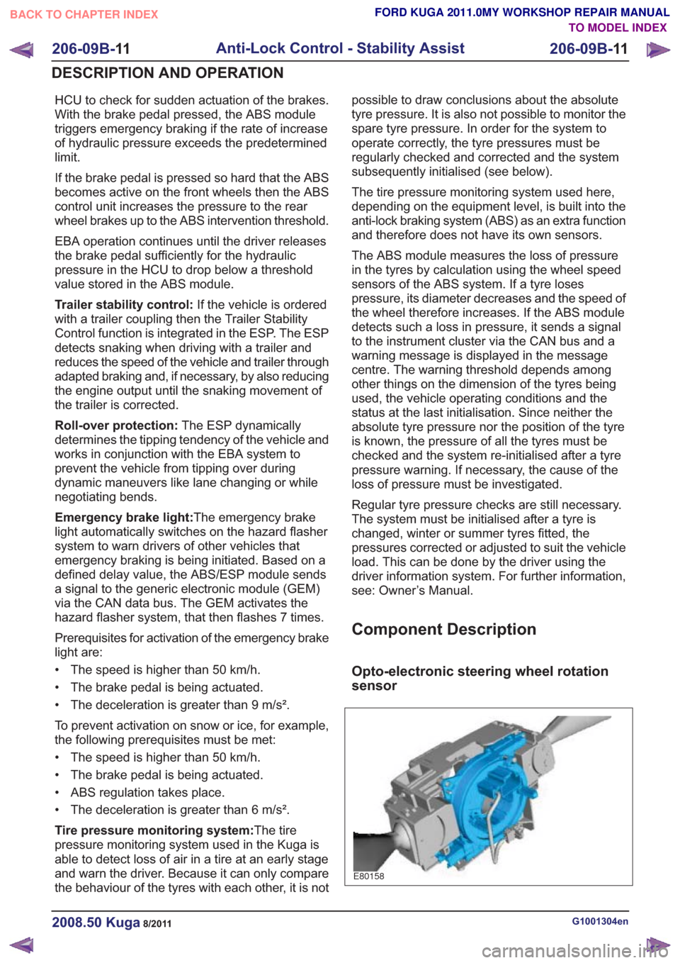
Opto-electronic steering wheel rotation
sensor
E80158
G1001304en2008.50 Kuga8/2011
206-09B-
11
Anti-Lock Control - Stability Assist
206-09B- 11
DESCRIPTION AND OPERATION
TO MODEL INDEX
BACK TO CHAPTER INDEX
FORD KUGA 2011.0MY WORKSHOP REPAIR MANUAL
Page 1433 of 2057
generate a square wave output signal. The signal
acts in proportion to the rotational speed of the
sensor ring. The ABS sensor rings are built into
the seals in the front wheel bearings. The ABS
module evaluates the signals from all four sensors
to calculate a vehicle speed signal based on the
rotational speeds of all wheels. The road speed is
transmitted on the CAN bus. The powertrain controlmodule (PCM) uses this signal and the
programmed tire size to calculate the vehicle
speed. The calculated vehicle speed is forwarded
on the CAN bus and is requested by other control
units that need this input information.
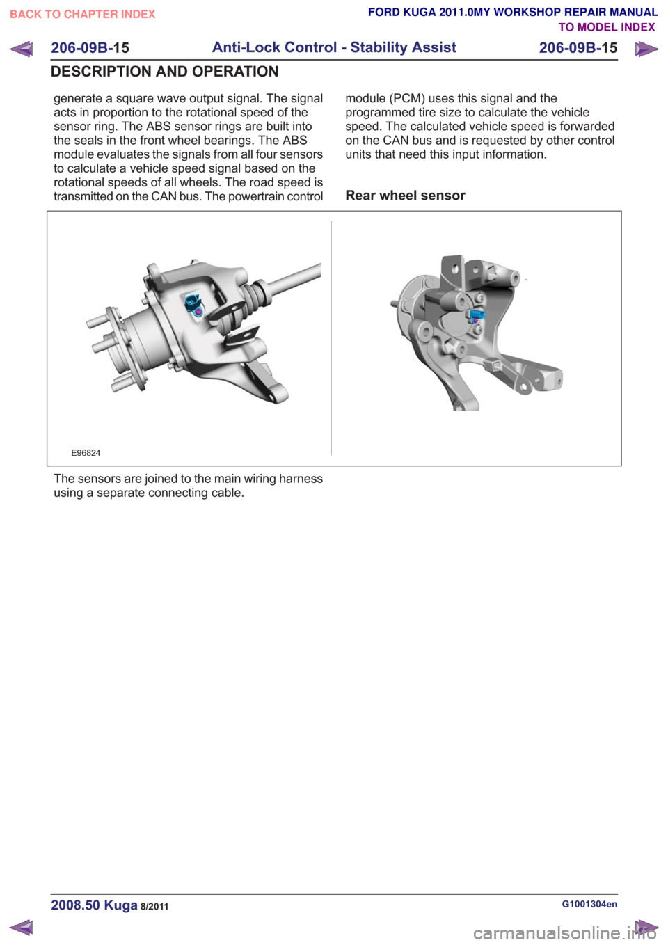
Rear wheel sensor
E96824
The sensors are joined to the main wiring harness
using a separate connecting cable.
G1001304en2008.50 Kuga8/2011
206-09B-
15
Anti-Lock Control - Stability Assist
206-09B- 15
DESCRIPTION AND OPERATION
TO MODEL INDEX
BACK TO CHAPTER INDEX
FORD KUGA 2011.0MY WORKSHOP REPAIR MANUAL