Page 1535 of 2057
DISASSEMBLY303-01-84
(21 134 8)
Engine ........................................................................\
....................................
DISASSEMBLY AND ASSEMBLY OF SUBASSEMBLIES 303-01-93
(21 165 6)
Cylinder Head ........................................................................\
.........................
ASSEMBLY 303-01-94
(21 134 8)
Engine ........................................................................\
....................................
INSTALLATION 303-01-112
(21 139 4)
Engine Accessories ........................................................................\
................
303-01-119
(21 132 0;
21 132 6;
21 132 7)
Engine — Vehicles With: 5-Speed Automatic Transaxle (AW55)
...................
303-01-2
Engine— 2.5L Duratec (147kW/200PS) - VI5303-01-
2
.
TO MODEL INDEX
BACK TO CHAPTER INDEX
PAGE 2 OF 2 FORD KUGA 2011.0MY WORKSHOP REPAIR MANUAL
Page 1547 of 2057

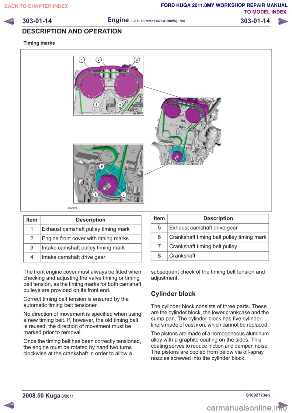
Timing marks
132
45
6
78
E62440
Description
Item
Exhaust camshaft pulley timing mark
1
Engine front cover with timing marks
2
Intake camshaft pulley timing mark
3
Intake camshaft drive gear
4Description
Item
Exhaust camshaft drive gear
5
Crankshaft timing belt pulley timing mark
6
Crankshaft timing belt pulley
7
Crankshaft
8
The front engine cover must always be fitted when
checking and adjusting the valve timing or timing
belt tension, as the timing marks for both camshaft
pulleys are provided on its front end.
Correct timing belt tension is ensured by the
automatic timing belt tensioner.
No direction of movement is specified when using
a new timing belt. If, however, the old timing belt
is reused, the direction of movement must be
marked prior to removal.
Once the timing belt has been correctly tensioned,
the engine must be rotated by hand two turns
clockwise at the crankshaft in order to allow a subsequent check of the timing belt tension and
adjustment.
Cylinder block
The cylinder block consists of three parts. These
are the cylinder block, the lower crankcase and the
sump pan. The cylinder block has five cylinder
liners made of cast iron, which cannot be replaced.
The pistons are made of a homogeneous aluminum
alloy with a graphite coating on the sides. This
coating serves to reduce friction and dampen noise.
The pistons are cooled from below via oil-spray
nozzles screwed into the cylinder block.
G1092773en2008.50 Kuga8/2011
303-01-
14
Engine— 2.5L Duratec (147kW/200PS) - VI5303-01-
14
DESCRIPTION AND OPERATION
TO MODEL INDEX
BACK TO CHAPTER INDEX
FORD KUGA 2011.0MY WORKSHOP REPAIR MANUAL
Page 1560 of 2057
Vehicles with mechanical timing belt tensioner
9.
E68488
1
3
2
Vehicles with automatic timing belt tensioner
10. WARNING: Take extra care whenhandling the compressed spring.
Install the Special Tool(s): 303-1054
1
2
E113799
303-1054
11. WARNING: Take extra care whenhandling the compressed spring.
Special Tool(s): 303-1054
E113800
1
2
3
303-1054
G543492en2008.50 Kuga8/2011
303-01- 27
Engine— 2.5L Duratec (147kW/200PS) - VI5303-01-
27
REMOVAL AND INSTALLATION
TO MODEL INDEX
BACK TO CHAPTER INDEX
FORD KUGA 2011.0MY WORKSHOP REPAIR MANUAL
Page 1561 of 2057
Installation
Vehicles with mechanical timing belt tensioner
1. NOTE:Make sure that new components are
installed.
1. Torque: 25
Nm
3. Torque: 25Nm
E68489
3
1
2
-20 C 20 C 50 C
Vehicles with automatic timing belt tensioner
2. NOTE: Make sure that new components are
installed.
1. Torque: 25
Nm
3. Special Tool(s): 303-1054 Torque: 25
Nm
E113801
12
3
303-1054
3. WARNING: Take extra care when handling the compressed spring.
Remove the Special Tool(s): 303-1054
E113802
303-1054
G543492en2008.50 Kuga8/2011
303-01- 28
Engine— 2.5L Duratec (147kW/200PS) - VI5303-01-
28
REMOVAL AND INSTALLATION
TO MODEL INDEX
BACK TO CHAPTER INDEX
FORD KUGA 2011.0MY WORKSHOP REPAIR MANUAL
Page 1573 of 2057
Vehicles with automatic timing belt tensioner
7. NOTE:Make sure that new components are
installed.
1. Torque: 25
Nm
3. Special Tool(s): 303-1054 Torque: 25
Nm
E113801
12
3
303-1054
8. WARNING: Take extra care when handling the compressed spring.
Remove the Special Tool(s): 303-1054
E113802
303-1054
All vehicles
9.Torque: 120Nm
E68746
10.Remove the Special Tool(s): 303-1178
E66324
303-1178
11 .Remove the Special Tool(s): 303-1182
E66328
303-1182
G1166799en2008.50 Kuga8/2011
303-01- 40
Engine— 2.5L Duratec (147kW/200PS) - VI5303-01-
40
REMOVAL AND INSTALLATION
TO MODEL INDEX
BACK TO CHAPTER INDEX
FORD KUGA 2011.0MY WORKSHOP REPAIR MANUAL
Page 1589 of 2057
Crankshaft Rear Seal(21 468 4)
Special Tool(s)303-1181
Installer, Crankshaft Rear
Seal
E62048
303-254
Locking Tool, Flywheel
21135
303-293
Remover, Crankshaft Seal
21143
Removal
Vehicles with manual transmission
1.
Vehicles with automatic transmission
2.Refer to: Transmission (307-01 Automatic
Transmission/Transaxle - Vehicles With:
5-Speed Automatic Transaxle - AW55 AWD,
Removal).
All vehicles
3. Special Tool(s): 303-254
E64889
4.Special Tool(s): 303-293
E64890
303-293
G1268481en2008.50 Kuga8/2011
303-01- 56
Engine— 2.5L Duratec (147kW/200PS) - VI5303-01-
56
REMOVAL AND INSTALLATION
TO MODEL INDEX
BACK TO CHAPTER INDEX
FORD KUGA 2011.0MY WORKSHOP REPAIR MANUAL
Page 1590 of 2057

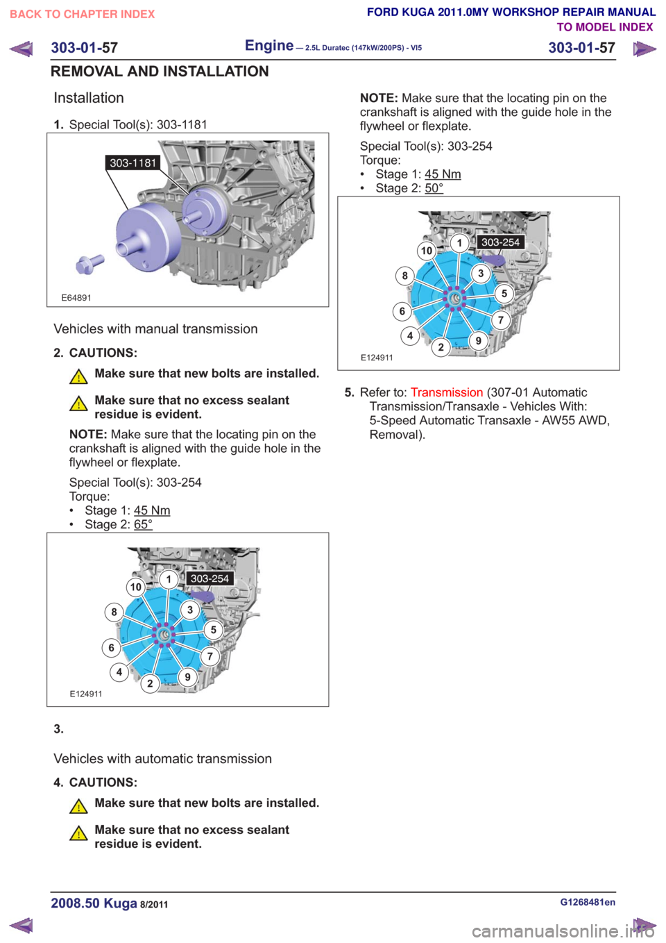
Installation
1.Special Tool(s): 303-1181
E64891
303-1181
Vehicles with manual transmission
2. CAUTIONS:
Make sure that new bolts are installed.
Make sure that no excess sealant
residue is evident.
NOTE: Make sure that the locating pin on the
crankshaft is aligned with the guide hole in the
flywheel or flexplate.
Special Tool(s): 303-254
Torque:
• Stage 1: 45
Nm
• Stage 2: 65°
E124911
1
2
3
4
5
67
8
9
10
3.
Vehicles with automatic transmission
4. CAUTIONS:
Make sure that new bolts are installed.
Make sure that no excess sealant
residue is evident. NOTE:
Make sure that the locating pin on the
crankshaft is aligned with the guide hole in the
flywheel or flexplate.
Special Tool(s): 303-254
Torque:
• Stage 1: 45
Nm
• Stage 2: 50°
E124911
1
2
3
4
5
67
8
9
10
5. Refer to: Transmission (307-01 Automatic
Transmission/Transaxle - Vehicles With:
5-Speed Automatic Transaxle - AW55 AWD,
Removal).
G1268481en2008.50 Kuga8/2011
303-01- 57
Engine— 2.5L Duratec (147kW/200PS) - VI5303-01-
57
REMOVAL AND INSTALLATION
TO MODEL INDEX
BACK TO CHAPTER INDEX
FORD KUGA 2011.0MY WORKSHOP REPAIR MANUAL
Page 1592 of 2057
Engine — Vehicles With: 5-Speed Automatic Transaxle(AW55)(21 132 0; 21 132 6; 21 132 7)
Removal
Special Tool(s) / General Equipment
303-122
Lifting Bracket, Engine
21068A
Cable Ties
Hose Clamp Remover/Installer
Hydraulic Jib Crane
Mounting Table Set
Special Tool(s) / General EquipmentRetaining Strap
Trolley Jack
Wooden Block
1. Refer to: Fuel System Pressure Release
(310-00 Fuel System - General Information,
General Procedures).
2. Refer to: Cowl Panel Grille (501-02 Front End
Body Panels, Removal and Installation).
3. Refer to: Battery(414-01 Battery, Mounting and
Cables, Removal and Installation).
4.
E114689
5. On both sides.
Loosen: 3
turn(s)
E99147
x3
G1191240en2008.50 Kuga8/2011
303-01- 59
Engine— 2.5L Duratec (147kW/200PS) - VI5303-01-
59
REMOVAL
TO MODEL INDEX
BACK TO CHAPTER INDEX
FORD KUGA 2011.0MY WORKSHOP REPAIR MANUAL