2011 FORD KUGA automatic
[x] Cancel search: automaticPage 1722 of 2057
Description
Item
PWM (pulse width modulation) signal
Comments:from PCM (powertrain control module)
5
Atmospheric pressure
6
Turbocharger boost pressure.
7
from air filter
8
Intake air
9Description
Item
Recirculated air valveRefertoComponentDescription:(page
7)
10
Vacuum line, recirculated air valve
11
to intake manifold
12
Throttle plate
13
Compressor
14
Turbine
15
System Operation
Turbocharger(s)
The TC consists of a turbine and a compressor.
The turbine is driven by the exhaust gas flow. A
common shaft drives the compressor and this then
compresses the intake air.
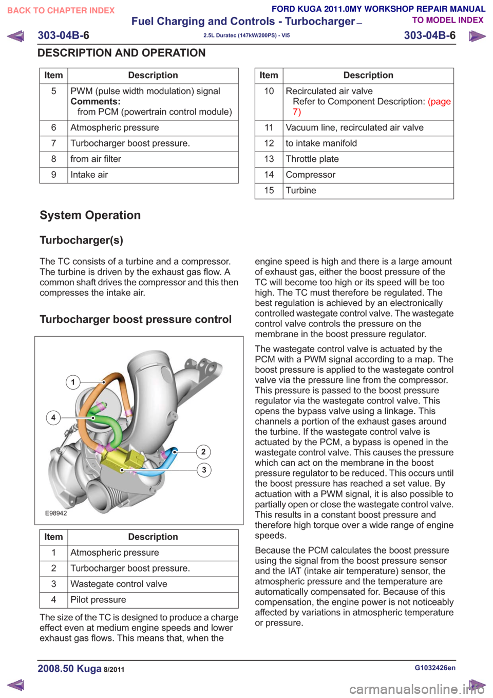
Turbocharger boost pressure control
E98942
1
2
3
4
Description
Item
Atmospheric pressure
1
Turbocharger boost pressure.
2
Wastegate control valve
3
Pilot pressure
4
The size of the TC is designed to produce a charge
effect even at medium engine speeds and lower
exhaust gas flows. This means that, when the engine speed is high and there is a large amount
of exhaust gas, either the boost pressure of the
TC will become too high or its speed will be too
high. The TC must therefore be regulated. The
best regulation is achieved by an electronically
controlled wastegate control valve. The wastegate
control valve controls the pressure on the
membrane in the boost pressure regulator.
The wastegate control valve is actuated by the
PCM with a PWM signal according to a map. The
boost pressure is applied to the wastegate control
valve via the pressure line from the compressor.
This pressure is passed to the boost pressure
regulator via the wastegate control valve. This
opens the bypass valve using a linkage. This
channels a portion of the exhaust gases around
the turbine. If the wastegate control valve is
actuated by the PCM, a bypass is opened in the
wastegate control valve. This causes the pressure
which can act on the membrane in the boost
pressure regulator to be reduced. This occurs until
the boost pressure has reached a set value. By
actuation with a PWM signal, it is also possible to
partially open or close the wastegate control valve.
This results in a constant boost pressure and
therefore high torque over a wide range of engine
speeds.
Because the PCM calculates the boost pressure
using the signal from the boost pressure sensor
and the IAT (intake air temperature) sensor, the
atmospheric pressure and the temperature are
automatically compensated for. Because of this
compensation, the engine power is not noticeably
affected by variations in atmospheric temperature
or pressure.
G1032426en2008.50 Kuga8/2011
303-04B-
6
Fuel Charging and Controls - Turbocharger
—
2.5L Duratec (147kW/200PS) - VI5
303-04B- 6
DESCRIPTION AND OPERATION
TO MODEL INDEX
BACK TO CHAPTER INDEX
FORD KUGA 2011.0MY WORKSHOP REPAIR MANUAL
Page 1748 of 2057
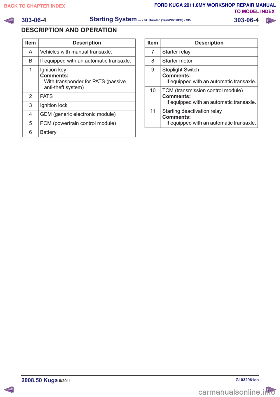
Description
Item
Vehicles with manual transaxle.
A
If equipped with an automatic transaxle.
B
Ignition key
Comments:With transponder for PATS (passive
anti-theft system)
1
PAT S
2
Ignition lock
3
GEM (generic electronic module)
4
PCM (powertrain control module)
5
Battery
6Description
Item
Starter relay
7
Starter motor
8
Stoplight Switch
Comments:If equipped with an automatic transaxle.
9
TCM (transmission control module)
Comments:If equipped with an automatic transaxle.
10
Starting deactivation relay
Comments:If equipped with an automatic transaxle.
11
G1032961en2008.50 Kuga8/2011
303-06-
4
Starting System— 2.5L Duratec (147kW/200PS) - VI5303-06-
4
DESCRIPTION AND OPERATION
TO MODEL INDEX
BACK TO CHAPTER INDEX
FORD KUGA 2011.0MY WORKSHOP REPAIR MANUAL
Page 1751 of 2057
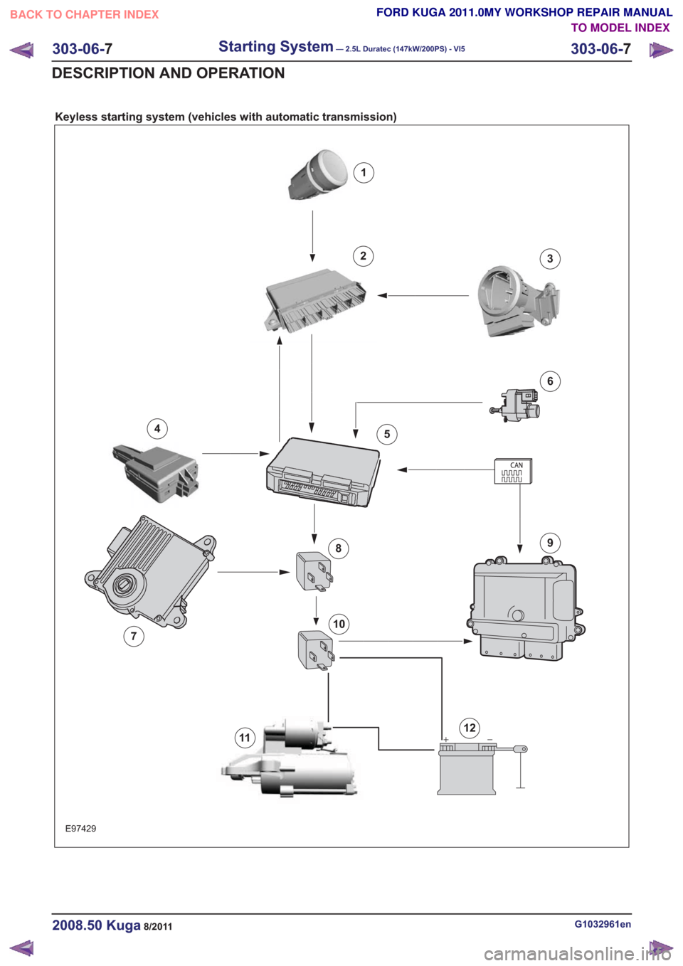
Keyless starting system (vehicles with automatic transmission)
E97429
1
23
45
6
7
89
10
1112
G1032961en2008.50 Kuga8/2011
303-06-7
Starting System— 2.5L Duratec (147kW/200PS) - VI5303-06-
7
DESCRIPTION AND OPERATION
TO MODEL INDEX
BACK TO CHAPTER INDEX
FORD KUGA 2011.0MY WORKSHOP REPAIR MANUAL
Page 1752 of 2057
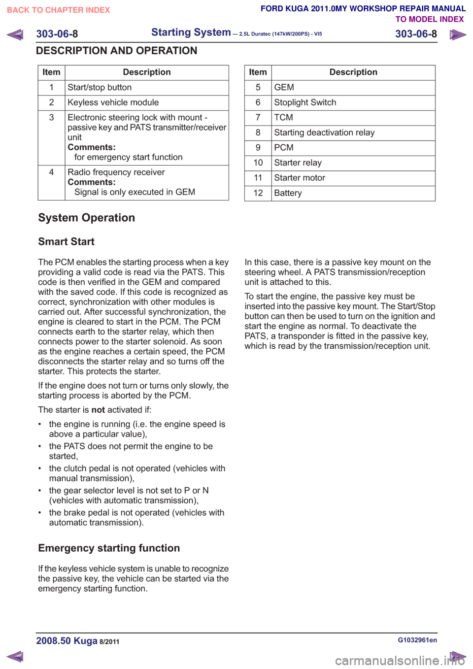
Description
Item
Start/stop button
1
Keyless vehicle module
2
Electronic steering lock with mount -
passive key and PATS transmitter/receiver
unit
Comments:for emergency start function
3
Radio frequency receiver
Comments:Signal is only executed in GEM
4Description
Item
GEM
5
Stoplight Switch
6
TCM7
Starting deactivation relay
8
PCM
9
Starter relay
10
Starter motor
11
Battery
12
System Operation
Smart Start
The PCM enables the starting process when a key
providing a valid code is read via the PATS. This
code is then verified in the GEM and compared
with the saved code. If this code is recognized as
correct, synchronization with other modules is
carried out. After successful synchronization, the
engine is cleared to start in the PCM. The PCM
connects earth to the starter relay, which then
connects power to the starter solenoid. As soon
as the engine reaches a certain speed, the PCM
disconnects the starter relay and so turns off the
starter. This protects the starter.
If the engine does not turn or turns only slowly, the
starting process is aborted by the PCM.
The starter is notactivated if:
• the engine is running (i.e. the engine speed is above a particular value),
• the PATS does not permit the engine to be started,
• the clutch pedal is not operated (vehicles with manual transmission),
• the gear selector level is not set to P or N (vehicles with automatic transmission),
• the brake pedal is not operated (vehicles with automatic transmission).
Emergency starting function
If the keyless vehicle system is unable to recognize
the passive key, the vehicle can be started via the
emergency starting function. In this case, there is a passive key mount on the
steering wheel. A PATS transmission/reception
unit is attached to this.
To start the engine, the passive key must be
inserted into the passive key mount. The Start/Stop
button can then be used to turn on the ignition and
start the engine as normal. To deactivate the
PATS, a transponder is fitted in the passive key,
which is read by the transmission/reception unit.
G1032961en2008.50 Kuga8/2011
303-06-
8
Starting System— 2.5L Duratec (147kW/200PS) - VI5303-06-
8
DESCRIPTION AND OPERATION
TO MODEL INDEX
BACK TO CHAPTER INDEX
FORD KUGA 2011.0MY WORKSHOP REPAIR MANUAL
Page 1796 of 2057
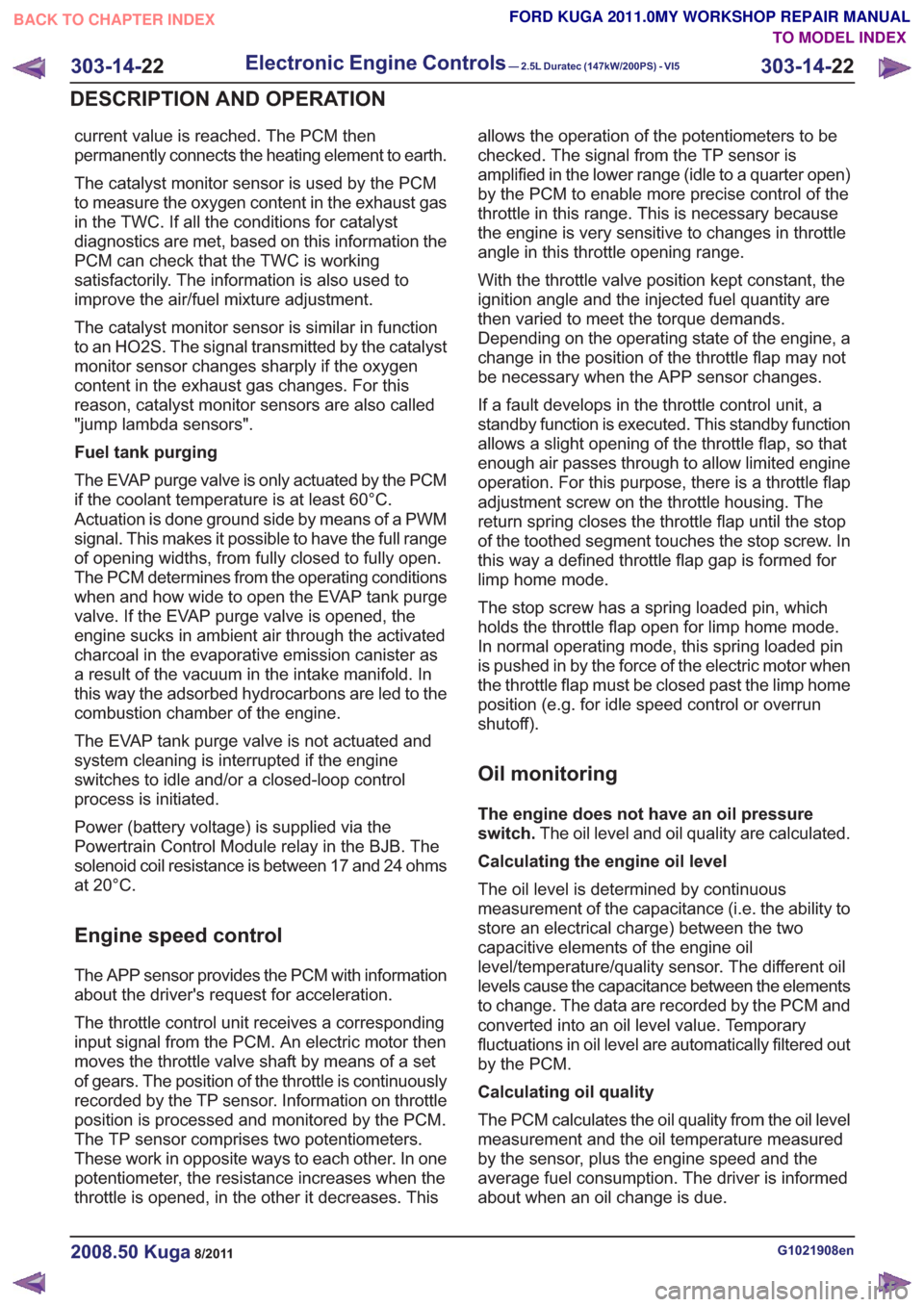
current value is reached. The PCM then
permanently connects the heating element to earth.
The catalyst monitor sensor is used by the PCM
to measure the oxygen content in the exhaust gas
in the TWC. If all the conditions for catalyst
diagnostics are met, based on this information the
PCM can check that the TWC is working
satisfactorily. The information is also used to
improve the air/fuel mixture adjustment.
The catalyst monitor sensor is similar in function
to an HO2S. The signal transmitted by the catalyst
monitor sensor changes sharply if the oxygen
content in the exhaust gas changes. For this
reason, catalyst monitor sensors are also called
"jump lambda sensors".
Fuel tank purging
The EVAP purge valve is only actuated by the PCM
if the coolant temperature is at least 60°C.
Actuation is done ground side by means of a PWM
signal. This makes it possible to have the full range
of opening widths, from fully closed to fully open.
The PCM determines from the operating conditions
when and how wide to open the EVAP tank purge
valve. If the EVAP purge valve is opened, the
engine sucks in ambient air through the activated
charcoal in the evaporative emission canister as
a result of the vacuum in the intake manifold. In
this way the adsorbed hydrocarbons are led to the
combustion chamber of the engine.
The EVAP tank purge valve is not actuated and
system cleaning is interrupted if the engine
switches to idle and/or a closed-loop control
process is initiated.
Power (battery voltage) is supplied via the
Powertrain Control Module relay in the BJB. The
solenoid coil resistance is between 17 and 24 ohms
at 20°C.
Engine speed control
The APP sensor provides the PCM with information
about the driver's request for acceleration.
The throttle control unit receives a corresponding
input signal from the PCM. An electric motor then
moves the throttle valve shaft by means of a set
of gears. The position of the throttle is continuously
recorded by the TP sensor. Information on throttle
position is processed and monitored by the PCM.
The TP sensor comprises two potentiometers.
These work in opposite ways to each other. In one
potentiometer, the resistance increases when the
throttle is opened, in the other it decreases. Thisallows the operation of the potentiometers to be
checked. The signal from the TP sensor is
amplified in the lower range (idle to a quarter open)
by the PCM to enable more precise control of the
throttle in this range. This is necessary because
the engine is very sensitive to changes in throttle
angle in this throttle opening range.
With the throttle valve position kept constant, the
ignition angle and the injected fuel quantity are
then varied to meet the torque demands.
Depending on the operating state of the engine, a
change in the position of the throttle flap may not
be necessary when the APP sensor changes.
If a fault develops in the throttle control unit, a
standby function is executed. This standby function
allows a slight opening of the throttle flap, so that
enough air passes through to allow limited engine
operation. For this purpose, there is a throttle flap
adjustment screw on the throttle housing. The
return spring closes the throttle flap until the stop
of the toothed segment touches the stop screw. In
this way a defined throttle flap gap is formed for
limp home mode.
The stop screw has a spring loaded pin, which
holds the throttle flap open for limp home mode.
In normal operating mode, this spring loaded pin
is pushed in by the force of the electric motor when
the throttle flap must be closed past the limp home
position (e.g. for idle speed control or overrun
shutoff).
Oil monitoring
The engine does not have an oil pressure
switch.
The oil level and oil quality are calculated.
Calculating the engine oil level
The oil level is determined by continuous
measurement of the capacitance (i.e. the ability to
store an electrical charge) between the two
capacitive elements of the engine oil
level/temperature/quality sensor. The different oil
levels cause the capacitance between the elements
to change. The data are recorded by the PCM and
converted into an oil level value. Temporary
fluctuations in oil level are automatically filtered out
by the PCM.
Calculating oil quality
The PCM calculates the oil quality from the oil level
measurement and the oil temperature measured
by the sensor, plus the engine speed and the
average fuel consumption. The driver is informed
about when an oil change is due.
G1021908en2008.50 Kuga8/2011
303-14- 22
Electronic Engine Controls— 2.5L Duratec (147kW/200PS) - VI5303-14-
22
DESCRIPTION AND OPERATION
TO MODEL INDEX
BACK TO CHAPTER INDEX
FORD KUGA 2011.0MY WORKSHOP REPAIR MANUAL
Page 1822 of 2057
SECTION 307-01 Automatic Transmission/Transaxle
— Vehicles With: 5-Speed Automatic Transaxle - AW55 AWD
VEHICLE APPLICATION:2008.50 Kuga
PA G E
CONTENTS
SPECIFICATIONS
307-01-4
Specifications ........................................................................\
..............................................
DESCRIPTION AND OPERATION 307-01-5
Transmission Description (Component Location) ...............................................................
307-01-6
Transmission Description (Overview) ........................................................................\
.........
307-01-6
Components of the AW55 automatic transaxle ..................................................................
307-01-6
General overview ........................................................................\
....................................
307-01-8
Transaxle cooling ........................................................................\
....................................
307-01-8
External shift mechanism ........................................................................\
........................
307-01-9
Components of the electronic control ........................................................................\
.....
307-01-11
Overview of the brakes, clutches and one-way clutches ................................................
307-01-12
Input and output signals at the TCM ........................................................................\
.......
307-01-14
Knowing and Understanding Customer Concerns ..........................................................
307-01-14
Testing Possible Causes of Transmission Control Faults ...............................................
307-01-14
IDS Diagnosis ........................................................................\
.........................................
307-01-14
visual inspection ........................................................................\
.....................................
307-01-15
Towing the vehicle ........................................................................\
..................................
307-01-15
Push-starting the Vehicle ........................................................................\
........................
307-01-15
Jump-starting the Vehicle ........................................................................\
.......................
307-01-15
Selector Lever Emergency Release ........................................................................\
.......
307-01-16
Adjusting the Selector Lever Cable ........................................................................\
........
307-01-17
Transmission Fluid Level Check ........................................................................\
.............
307-01-17
Changing the Transmission Fluid ........................................................................\
...........
307-01-18
Diagnosis with IDS ........................................................................\
..................................
307-01-19
Resetting the counter for fluid change intervals. .............................................................
307-01-19
Programming the 'N' position of the TR sensor..............................................................
307-01-19
Resetting the values learned by the TCM .......................................................................
307-01-21
Transmission Description (System Operation and Component Description) .....................
307-01-21
System Operation ........................................................................\
.......................................
307-01-22
Functionality overview ........................................................................\
............................
307-01-24
Electronic Control System ........................................................................\
......................
307-01-24
Hydraulic Control System ........................................................................\
.......................
307-01-24
Type plate ........................................................................\
...............................................
307-01-25
Serial number of the transmission ........................................................................\
..........
307-01-25
Markings on the TCM ........................................................................\
.............................
307-01-25
Serial
number of the TCM ........................................................................\
.......................
307-01-25
Transmission Control ........................................................................\
..............................
307-01-27
Pin assignment for TCM connector 'C' (connection to transaxle) ...................................
307-01-28
Operation ........................................................................\
................................................
307-01-29
Gearshift control ........................................................................\
......................................
307-01-29
Adaptation ........................................................................\
...............................................
307-01-29
Shifting from 'P' to another transmission range ..............................................................
307-01-1
Automatic Transmission/Transaxle
— Vehicles With:
5-Speed Automatic Transaxle - AW55 AWD
307-01- 1
.
TO MODEL INDEX
BACK TO CHAPTER INDEX
PAGE 1 OF 3 FORD KUGA 2011.0MY WORKSHOP REPAIR MANUAL
Page 1823 of 2057
307-01-29
Automatic transmission, selector lever in position "D". ...................................................
307-01-29
Sport mode, selector lever in position "S" .......................................................................
307-01-29
Changing gear in select-shift mode........................................................................\
........
307-01-30
Selector lever from 'N' to 'R' position ........................................................................\
......
307-01-30
Self-test and Diagnosis ........................................................................\
...........................
307-01-30
Temperature controlled torque converter lockup ............................................................
307-01-30
Slip locking ........................................................................\
..............................................
307-01-30
Hill climbing ........................................................................\
.............................................
307-01-31
Downhill driving ........................................................................\
.......................................
307-01-31
Hill-hold function ........................................................................\
.....................................
307-01-31
Altitude correction ........................................................................\
...................................
307-01-31
Selector lever lock ........................................................................\
..................................
307-01-31
Shifting from P into another transmission range .............................................................
307-01-31
Shifting from N into another transmission range .............................................................
307-01-31
Power flow through the transmission ........................................................................\
......
307-01-31
Clutches and brakes ........................................................................\
...............................
307-01-33
Position P (park) ........................................................................\
.....................................
307-01-34
Position N (neutral) ........................................................................\
.................................
307-01-35
Position D, 1st gear........................................................................\
................................
307-01-36
Position D, 2nd gear ........................................................................\
...............................
307-01-37
Position D, 3rd gear ........................................................................\
................................
307-01-38
Position D, 4th gear ........................................................................\
................................
307-01-39
Position D, 5th gear ........................................................................\
................................
307-01-40
Position R (reverse) ........................................................................\
................................
307-01-41
Service instructions ........................................................................\
.................................
307-01-41
Towing procedure ........................................................................\
...................................
307-01-42
Reset adaptation data ........................................................................\
.............................
307-01-42
Limp home mode ........................................................................\
....................................
307-01-42
Component Description ........................................................................\
..............................
Tasks of the electronic components ........................................................................\
........
307-01-44
Input signals ........................................................................\
............................................
307-01-45
Output signals ........................................................................\
.........................................
Control valve assembly ........................................................................\
...........................
Shift solenoids S1 - S5 ........................................................................\
...........................
PWM-
solenoid valve – TCC (SLU) ........................................................................\
........
PWM solenoid valve – shift pressure (SLS) ...................................................................
PWM solenoid valve for main line pressure (SLT) ..........................................................
307-01-52
Installation position ........................................................................\
.................................
Operation ........................................................................\
................................................
Selector lever with integrated select-shift switch module ...............................................
Oil pump ........................................................................\
..................................................
Torque converter with TCC ........................................................................\
.....................
The TSS sensor ........................................................................\
......................................
The OSS sensor ........................................................................\
.....................................
The TFT sensor ........................................................................\
......................................
The TR sensor ........................................................................\
........................................
GENERAL PROCEDURES
T ransmission Fluid Level Check ........................................................................\
.................
307-01-63
T ransmission Fluid Drain and Refill ........................................................................\
............
REMOVAL AND INSTALLATION 307-01-67
Halfshaft Seal LH ........................................................................\
........................................
307-01-68
Halfshaft Seal RH........................................................................\
.......................................
307-01-69
Main Control Valve Body ........................................................................\
............................
307-01-2
Automatic Transmission/Transaxle
— Vehicles With:
5-Speed Automatic Transaxle - AW55 AWD
307-01- 2
.
TO MODEL INDEX
BACK TO CHAPTER INDEX
307-01-42
307-01-49
307-01-52 307-01-47
307-01-45
307-01-50
307-01-51
307-01-53
307-01-55
307-01-54
307-01-56
307-01-57
307-01-58
307-01-61 307-01-60
PAGE 2 OF 3 FORD KUGA 2011.0MY WORKSHOP REPAIR MANUAL
Page 1824 of 2057
307-01-72
Output Shaft Speed (OSS) Sensor ........................................................................\
.............
307-01-73
Torque Converter Seal ........................................................................\
................................
307-01-75
Transmission Fluid Pan ........................................................................\
..............................
307-01-77
Transmission Range (TR) Sensor ........................................................................\
..............
307-01-81
Turbine Shaft Speed (TSS) Sensor ........................................................................\
............
REMOVAL 307-01-82
Transmission ........................................................................\
..............................................
INSTALLATION 307-01-91
Transmission ........................................................................\
..............................................
307-01-3
Automatic Transmission/Transaxle
— Vehicles With:
5-Speed Automatic Transaxle - AW55 AWD
307-01- 3
.
TO MODEL INDEX
BACK TO CHAPTER INDEX
PAGE 3 OF 3 FORD KUGA 2011.0MY WORKSHOP REPAIR MANUAL
FORD KUGA 2011.0MY WORKSHOP REPAIR MANUAL