2011 FORD KUGA Front suspension
[x] Cancel search: Front suspensionPage 1203 of 2057
SECTION 204-02 Rear Suspension
VEHICLE APPLICATION:2008.50 Kuga
PA G E
CONTENTS
SPECIFICATIONS
204-02-2
Specifications ........................................................................\
..............................................
DESCRIPTION AND OPERATION 204-02-3
Rear Suspension (Overview) ........................................................................\
......................
204-02-3
Overview ........................................................................\
.....................................................
204-02-4
Upper control arm ........................................................................\
.......................................
204-02-4
Rear lower arm and spring lower pad ........................................................................\
.........
204-02-4
Front lower arm ........................................................................\
..........................................
204-02-5
Stabilizer bar ........................................................................\
...............................................
REMOVAL AND INSTALLATION 204-02-6
Wheel Bearing and Wheel Hub ........................................................................\
..................
204-02-9
(15 701 0)
Upper Arm ........................................................................\
..............................
204-02-11
(15 690 0)
Front Lower Arm ........................................................................\
.....................
204-02-13
(15 705 0)
Rear Lower Arm ........................................................................\
.....................
204-02-15
(15 752 0)
Rear Stabilizer Bar ........................................................................\
.................
204-02-17
Rear Stabilizer Bar Link ........................................................................\
..............................
204-02-18
Rear Stabilizer Bar Bushing ........................................................................\
.......................
204-02-19
Wheel Knuckle — LHD FWD/RHD FWD ........................................................................\
....
204-02-22
Wheel Knuckle — LHD 4WD/RHD 4WD ........................................................................\
....
204-02-25
(15 621 0)
Spring ........................................................................\
.....................................
204-02- 1
Rear Suspension
204-02- 1
.
TO MODEL INDEX
BACK TO CHAPTER INDEX
FORD KUGA 2011.0MY WORKSHOP REPAIR MANUAL
Page 1205 of 2057
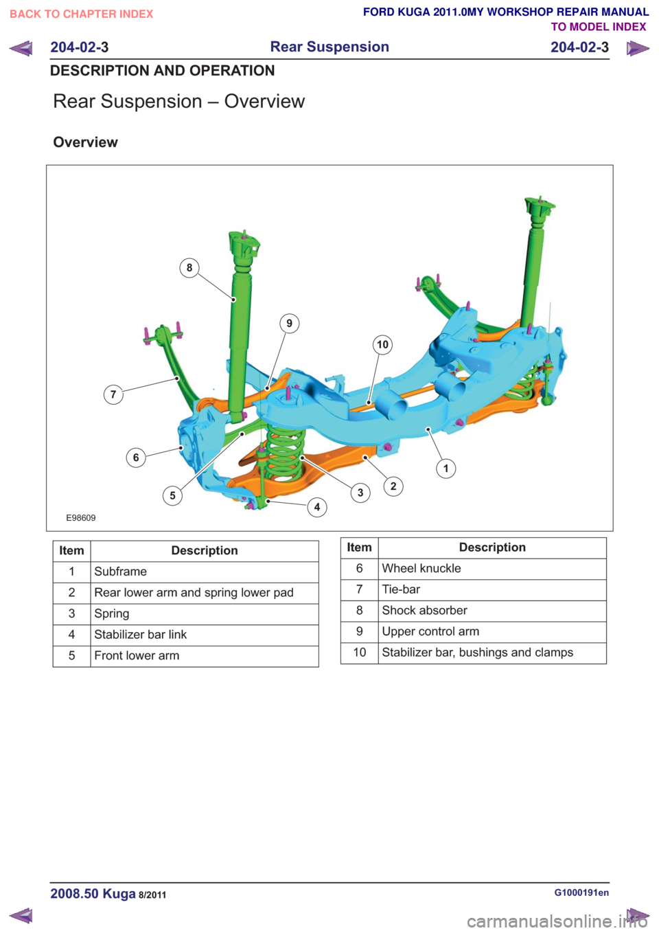
Rear Suspension – Overview
Overview
E98609
1
23
4
5
7
6
8
9
10
Description
Item
Subframe
1
Rear lower arm and spring lower pad
2
Spring
3
Stabilizer bar link
4
Front lower arm
5Description
Item
Wheel knuckle
6
Tie-bar
7
Shock absorber
8
Upper control arm
9
Stabilizer bar, bushings and clamps
10
G1000191en2008.50 Kuga8/2011
204-02- 3
Rear Suspension
204-02- 3
DESCRIPTION AND OPERATION
TO MODEL INDEX
BACK TO CHAPTER INDEX
FORD KUGA 2011.0MY WORKSHOP REPAIR MANUAL
Page 1206 of 2057
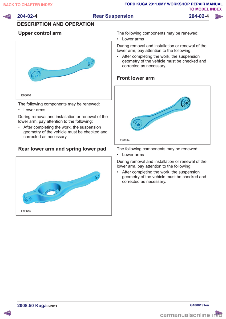
Upper control arm
E98616
The following components may be renewed:
• Lower arms
During removal and installation or renewal of the
lower arm, pay attention to the following:
• After completing the work, the suspensiongeometry of the vehicle must be checked and
corrected as necessary.
Rear lower arm and spring lower pad
E98615
The following components may be renewed:
• Lower arms
During removal and installation or renewal of the
lower arm, pay attention to the following:
• After completing the work, the suspensiongeometry of the vehicle must be checked and
corrected as necessary.
Front lower arm
E98614
The following components may be renewed:
• Lower arms
During removal and installation or renewal of the
lower arm, pay attention to the following:
• After completing the work, the suspensiongeometry of the vehicle must be checked and
corrected as necessary.
G1000191en2008.50 Kuga8/2011
204-02- 4
Rear Suspension
204-02- 4
DESCRIPTION AND OPERATION
TO MODEL INDEX
BACK TO CHAPTER INDEX
FORD KUGA 2011.0MY WORKSHOP REPAIR MANUAL
Page 1213 of 2057
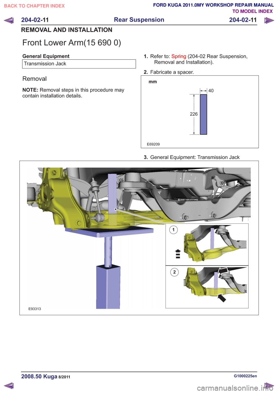
Front Lower Arm(15 690 0)
General EquipmentTransmission Jack
Removal
NOTE: Removal steps in this procedure may
contain installation details. 1.
Refer to: Spring(204-02 Rear Suspension,
Removal and Installation).
2. Fabricate a spacer.
E69209
226
40
3.General Equipment: Transmission Jack
1
2
E93313
G1000225en2008.50 Kuga8/2011
204-02- 11
Rear Suspension
204-02- 11
REMOVAL AND INSTALLATION
TO MODEL INDEX
BACK TO CHAPTER INDEX
FORD KUGA 2011.0MY WORKSHOP REPAIR MANUAL
Page 1235 of 2057
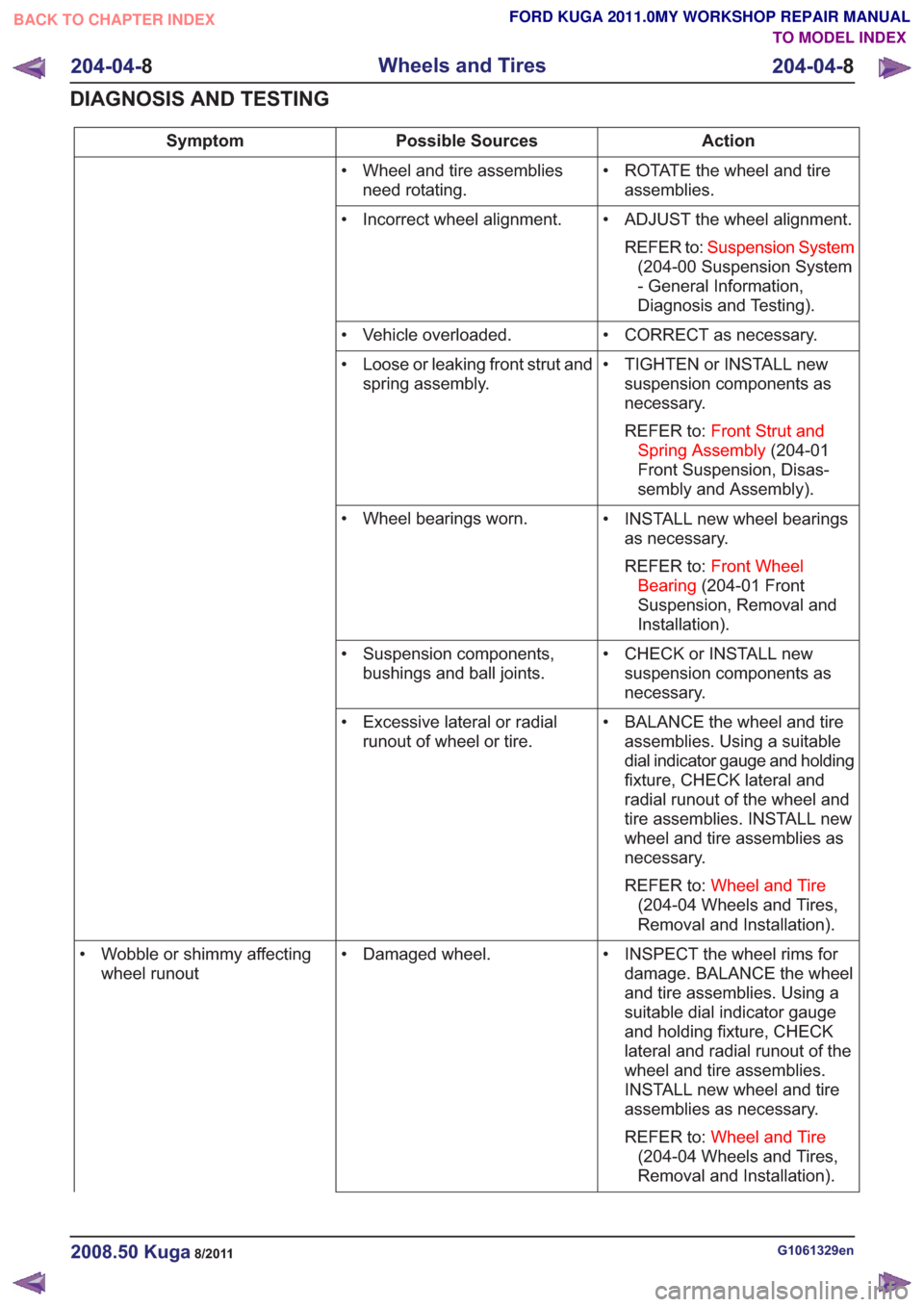
Action
Possible Sources
Symptom
• ROTATE the wheel and tireassemblies.
• Wheel and tire assemblies
need rotating.
• ADJUST the wheel alignment.REFER to: Suspension System
(204-00 Suspension System
- General Information,
Diagnosis and Testing).
• Incorrect wheel alignment.
• CORRECT as necessary.
• Vehicle overloaded.
• TIGHTEN or INSTALL newsuspension components as
necessary.
REFER to: Front Strut and
Spring Assembly (204-01
Front Suspension, Disas-
sembly and Assembly).
• Loose or leaking front strut and
spring assembly.
• INSTALL new wheel bearingsas necessary.
REFER to: Front Wheel
Bearing (204-01 Front
Suspension, Removal and
Installation).
• Wheel bearings worn.
• CHECK or INSTALL newsuspension components as
necessary.
• Suspension components,
bushings and ball joints.
• BALANCE the wheel and tireassemblies. Using a suitable
dial indicator gauge and holding
fixture, CHECK lateral and
radial runout of the wheel and
tire assemblies. INSTALL new
wheel and tire assemblies as
necessary.
REFER to: Wheel and Tire
(204-04 Wheels and Tires,
Removal and Installation).
• Excessive lateral or radial
runout of wheel or tire.
• INSPECT the wheel rims fordamage. BALANCE the wheel
and tire assemblies. Using a
suitable dial indicator gauge
and holding fixture, CHECK
lateral and radial runout of the
wheel and tire assemblies.
INSTALL new wheel and tire
assemblies as necessary.
REFER to: Wheel and Tire
(204-04 Wheels and Tires,
Removal and Installation).
• Damaged wheel.
• Wobble or shimmy affecting
wheel runout
G1061329en2008.50 Kuga8/2011
204-04- 8
Wheels and Tires
204-04- 8
DIAGNOSIS AND TESTING
TO MODEL INDEX
BACK TO CHAPTER INDEX
FORD KUGA 2011.0MY WORKSHOP REPAIR MANUAL
Page 1236 of 2057
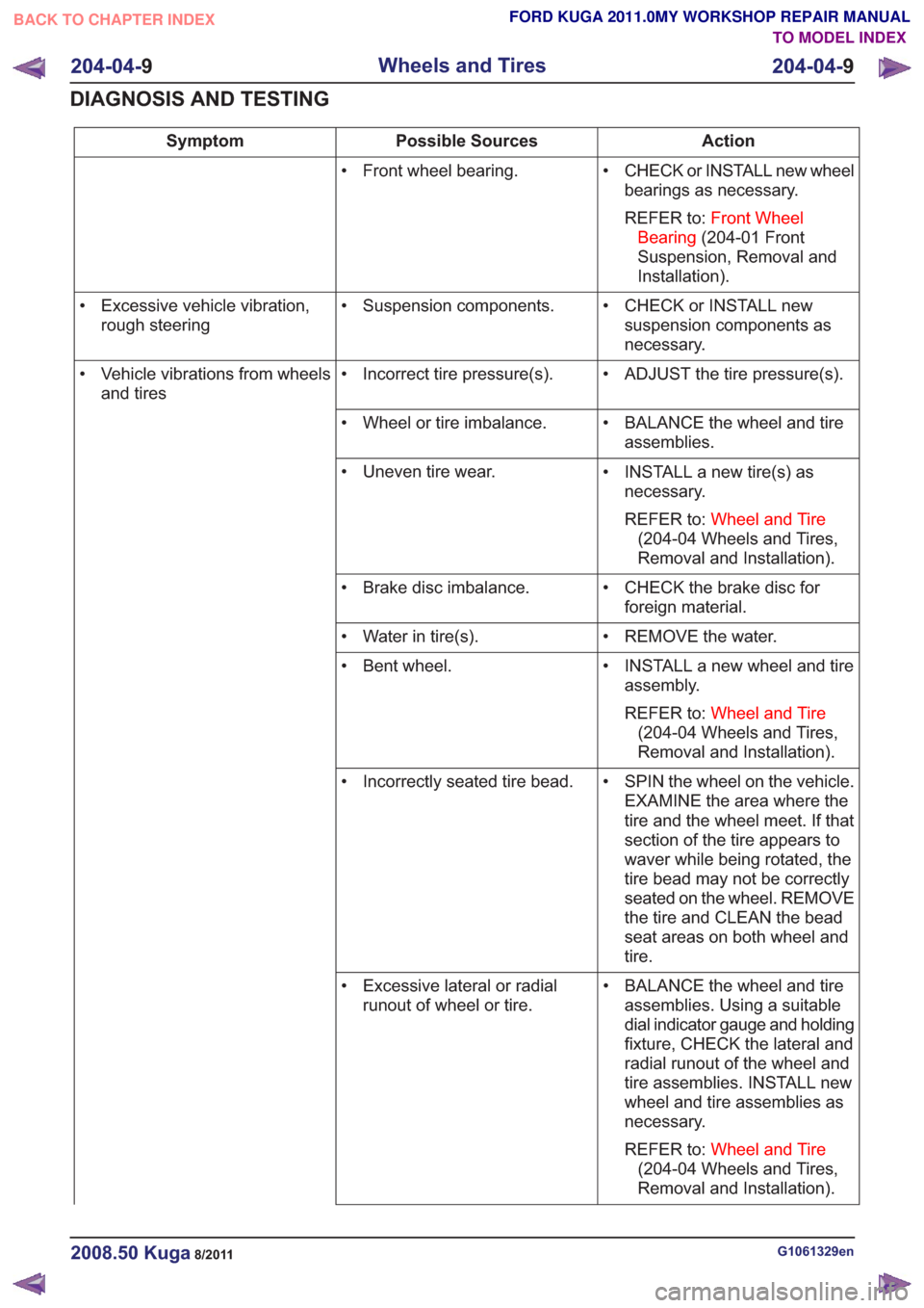
Action
Possible Sources
Symptom
• CHECK or INSTALL new wheelbearings as necessary.
REFER to: Front Wheel
Bearing (204-01 Front
Suspension, Removal and
Installation).
• Front wheel bearing.
• CHECK or INSTALL newsuspension components as
necessary.
• Suspension components.
• Excessive vehicle vibration,
rough steering
• ADJUST the tire pressure(s).
• Incorrect tire pressure(s).
• Vehicle vibrations from wheels
and tires
• BALANCE the wheel and tireassemblies.
• Wheel or tire imbalance.
• INSTALL a new tire(s) asnecessary.
REFER to: Wheel and Tire
(204-04 Wheels and Tires,
Removal and Installation).
• Uneven tire wear.
• CHECK the brake disc forforeign material.
• Brake disc imbalance.
• REMOVE the water.
• Water in tire(s).
• INSTALL a new wheel and tireassembly.
REFER to: Wheel and Tire
(204-04 Wheels and Tires,
Removal and Installation).
• Bent wheel.
• SPIN the wheel on the vehicle.EXAMINE the area where the
tire and the wheel meet. If that
section of the tire appears to
waver while being rotated, the
tire bead may not be correctly
seated on the wheel. REMOVE
the tire and CLEAN the bead
seat areas on both wheel and
tire.
• Incorrectly seated tire bead.
• BALANCE the wheel and tireassemblies. Using a suitable
dial indicator gauge and holding
fixture, CHECK the lateral and
radial runout of the wheel and
tire assemblies. INSTALL new
wheel and tire assemblies as
necessary.
REFER to: Wheel and Tire
(204-04 Wheels and Tires,
Removal and Installation).
• Excessive lateral or radial
runout of wheel or tire.
G1061329en2008.50 Kuga8/2011
204-04- 9
Wheels and Tires
204-04- 9
DIAGNOSIS AND TESTING
TO MODEL INDEX
BACK TO CHAPTER INDEX
FORD KUGA 2011.0MY WORKSHOP REPAIR MANUAL
Page 1237 of 2057
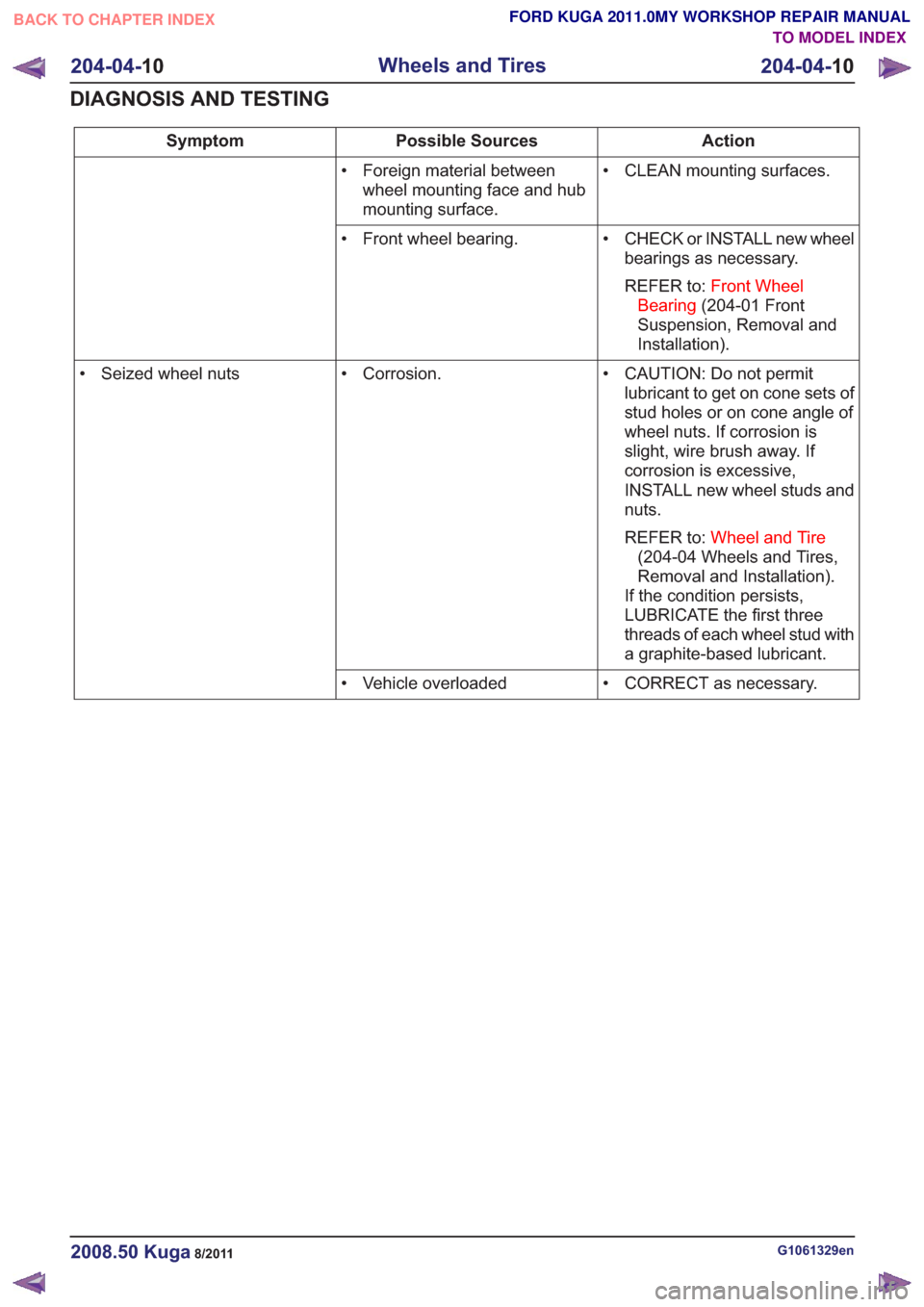
Action
Possible Sources
Symptom
• CLEAN mounting surfaces.
• Foreign material between
wheel mounting face and hub
mounting surface.
• CHECK or INSTALL new wheelbearings as necessary.
REFER to: Front Wheel
Bearing (204-01 Front
Suspension, Removal and
Installation).
• Front wheel bearing.
• CAUTION: Do not permitlubricant to get on cone sets of
stud holes or on cone angle of
wheel nuts. If corrosion is
slight, wire brush away. If
corrosion is excessive,
INSTALL new wheel studs and
nuts.
REFER to: Wheel and Tire
(204-04 Wheels and Tires,
Removal and Installation).
If the condition persists,
LUBRICATE the first three
threads of each wheel stud with
a graphite-based lubricant.
• Corrosion.
• Seized wheel nuts
• CORRECT as necessary.
• Vehicle overloaded
G1061329en2008.50 Kuga8/2011
204-04- 10
Wheels and Tires
204-04- 10
DIAGNOSIS AND TESTING
TO MODEL INDEX
BACK TO CHAPTER INDEX
FORD KUGA 2011.0MY WORKSHOP REPAIR MANUAL
Page 1298 of 2057
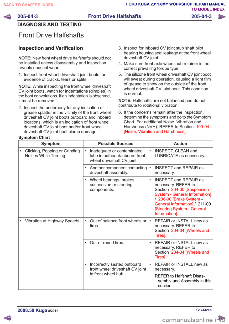
Front Drive Halfshafts
Inspection and Verification
NOTE:New front wheel drive halfshafts should not
be installed unless disassembly and inspection
reveals unusual wear.
1. Inspect front wheel driveshaft joint boots for evidence of cracks, tears or splits.
NOTE: While inspecting the front wheel driveshaft
CV joint boots, watch for indentations (dimples) in
the boot convolutions. If an indentation is observed,
it must be removed.
2. Inspect the underbody for any indication of grease splatter in the vicinity of the front wheel
driveshaft CV joint boots outboard and inboard
locations, which is an indication of front wheel
driveshaft CV joint boot and/or front wheel
driveshaft CV joint boot clamp damage. 3. Inspect for inboard CV joint stub shaft pilot
bearing housing seal leakage at the front wheel
driveshaft CV joint.
4. Make sure front axle wheel hub retainer is the correct prevailing torque type.
5. The silicone front wheel driveshaft CV joint boot will sweat during operation, causing a light film
of grease to show on the outside of the front
wheel driveshaft CV joint boot. This condition
is normal.
NOTE: Halfshafts are not balanced and do not
contribute to rotational vibration.
6. If the concerns remain after the inspection, determine the symptoms and go to the Symptom
Chart. For additional Noise, Vibration and
Harshness (NVH). REFER to Section 100-04
[Noise, Vibration and Harshness] .
Symptom Chart
Action
Possible Sources
Symptom
• INSPECT, CLEAN andLUBRICATE as necessary.
• Inadequate or contaminated
lube in outboard/inboard front
wheel driveshaft CV joint.
• Clicking, Popping or Grinding
Noises While Turning
• INSPECT and REPAIR asnecessary.
• Another component contacting
driveshaft assembly.
• INSPECT and REPAIR asnecessary. REFER to
Section 204-00 [Suspension
System - General Information]
/ 206-00 [Brake System -
General Information] /211-00
[Steering System - General
Information] .
• Wheel bearings, brakes,
suspension or steering
components.
• REPAIR or INSTALL new asnecessary. REFER to
Section 204-04 [Wheels and
Tires] .
• Out of balance front wheels or
tires.
• Vibration at Highway Speeds
• REPAIR or INSTALL new asnecessary. REFER to
Section 204-04 [Wheels and
Tires] .
• Out-of-round tires.
• REPAIR or INSTALL new asnecessary.
REFER to Halfshaft Disas-
semblv and Assembly in this
section.
• Incorrectly seated outboard
front wheel driveshaft CV joint
in front wheel hub.
G17442en2008.50 Kuga8/2011
205-04- 3
Front Drive Halfshafts
205-04- 3
DIAGNOSIS AND TESTING
TO MODEL INDEX
BACK TO CHAPTER INDEX
FORD KUGA 2011.0MY WORKSHOP REPAIR MANUAL