2011 FORD KUGA Front suspension
[x] Cancel search: Front suspensionPage 1299 of 2057
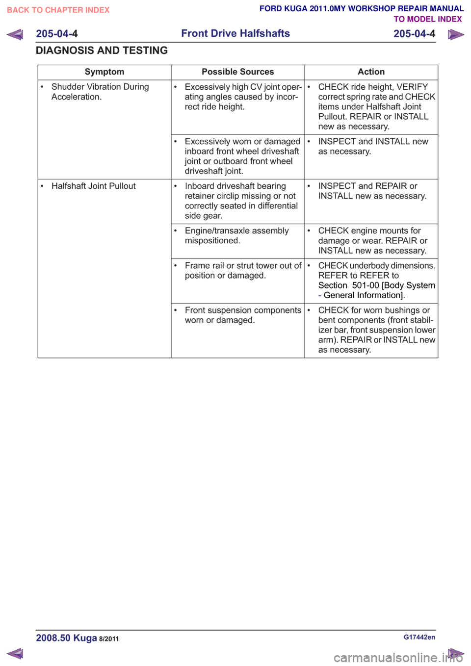
Action
Possible Sources
Symptom
• CHECK ride height, VERIFYcorrect spring rate and CHECK
items under Halfshaft Joint
Pullout. REPAIR or INSTALL
new as necessary.
• Excessively high CV joint oper-
ating angles caused by incor-
rect ride height.
• Shudder Vibration During
Acceleration.
• INSPECT and INSTALL newas necessary.
• Excessively worn or damaged
inboard front wheel driveshaft
joint or outboard front wheel
driveshaft joint.
• INSPECT and REPAIR orINSTALL new as necessary.
• Inboard driveshaft bearing
retainer circlip missing or not
correctly seated in differential
side gear.
• Halfshaft Joint Pullout
• CHECK engine mounts fordamage or wear. REPAIR or
INSTALL new as necessary.
• Engine/transaxle assembly
mispositioned.
• CHECK underbody dimensions.REFER to REFER to
Section 501-00 [Body System
-General Information] .
• Frame rail or strut tower out of
position or damaged.
• CHECK for worn bushings orbent components (front stabil-
izer bar, front suspension lower
arm). REPAIR or INSTALL new
as necessary.
• Front suspension components
worn or damaged.
G17442en2008.50 Kuga8/2011
205-04- 4
Front Drive Halfshafts
205-04- 4
DIAGNOSIS AND TESTING
TO MODEL INDEX
BACK TO CHAPTER INDEX
FORD KUGA 2011.0MY WORKSHOP REPAIR MANUAL
Page 1341 of 2057
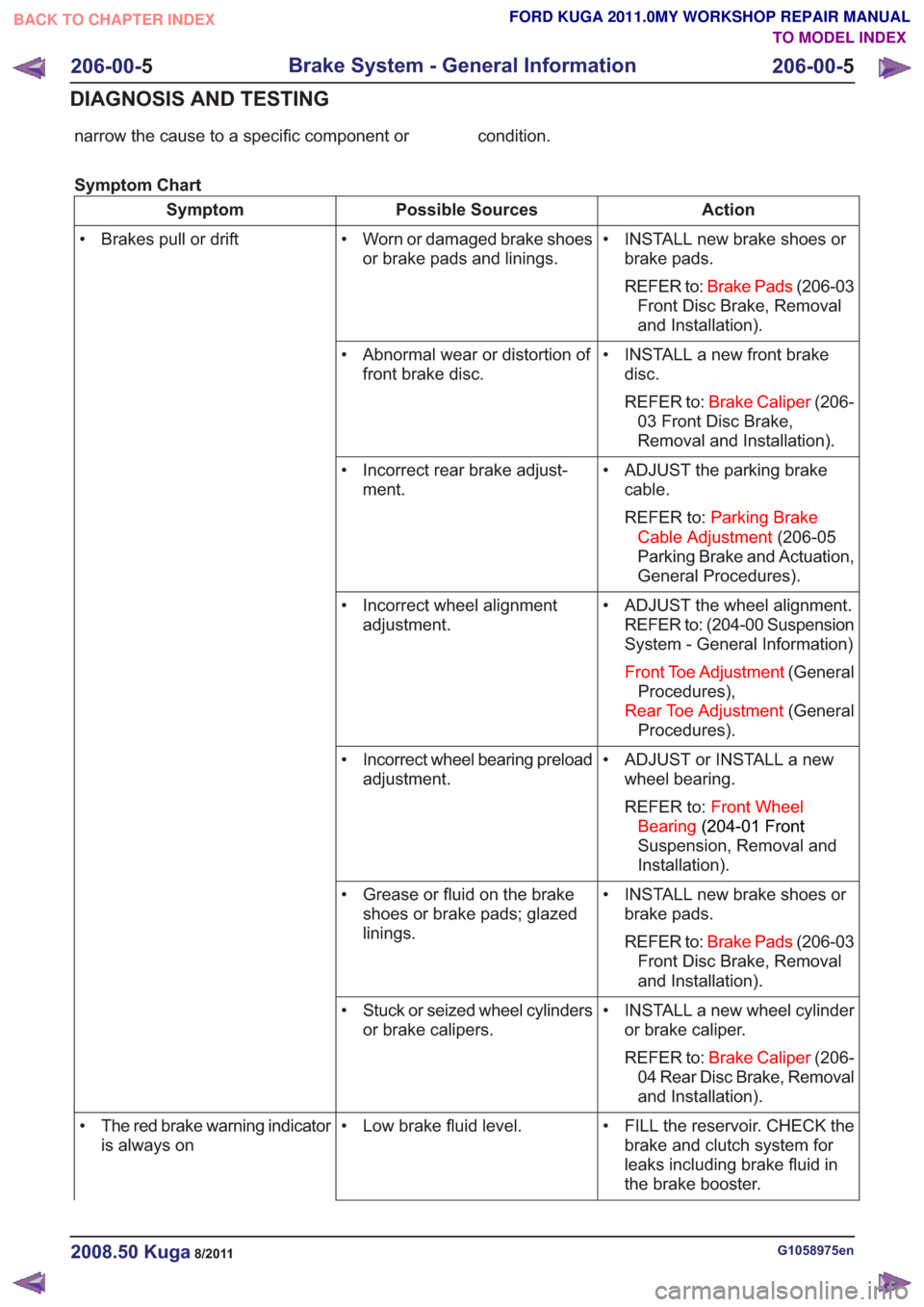
narrow the cause to a specific component or condition.
Symptom Chart
Action
Possible Sources
Symptom
• INSTALL new brake shoes orbrake pads.
REFER to: Brake Pads (206-03
Front Disc Brake, Removal
and Installation).
• Worn or damaged brake shoes
or brake pads and linings.
• Brakes pull or drift
• INSTALL a new front brakedisc.
REFER to: Brake Caliper (206-
03 Front Disc Brake,
Removal and Installation).
• Abnormal wear or distortion of
front brake disc.
• ADJUST the parking brakecable.
REFER to: Parking Brake
Cable Adjustment (206-05
Parking Brake and Actuation,
General Procedures).
• Incorrect rear brake adjust-
ment.
• ADJUST the wheel alignment.REFER to: (204-00 Suspension
System - General Information)
Front Toe Adjustment (General
Procedures),
Rear Toe Adjustment (General
Procedures).
• Incorrect wheel alignment
adjustment.
• ADJUST or INSTALL a newwheel bearing.
REFER to: Front Wheel
Bearing (204-01 Front
Suspension, Removal and
Installation).
• Incorrect wheel bearing preload
adjustment.
• INSTALL new brake shoes orbrake pads.
REFER to: Brake Pads (206-03
Front Disc Brake, Removal
and Installation).
• Grease or fluid on the brake
shoes or brake pads; glazed
linings.
• INSTALL a new wheel cylinderor brake caliper.
REFER to: Brake Caliper (206-
04 Rear Disc Brake, Removal
and Installation).
• Stuck or seized wheel cylinders
or brake calipers.
• FILL the reservoir. CHECK thebrake and clutch system for
leaks including brake fluid in
the brake booster.
• Low brake fluid level.
• The red brake warning indicator
is always on
G1058975en2008.50 Kuga8/2011
206-00- 5
Brake System - General Information
206-00- 5
DIAGNOSIS AND TESTING
TO MODEL INDEX
BACK TO CHAPTER INDEX
FORD KUGA 2011.0MY WORKSHOP REPAIR MANUAL
Page 1357 of 2057
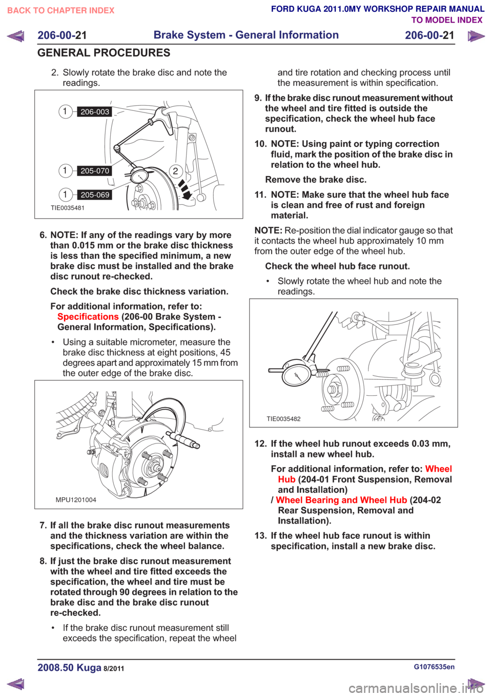
2. Slowly rotate the brake disc and note thereadings.
TIE0035481
2
206-0031
205-0701
205-0691
6. NOTE: If any of the readings vary by morethan 0.015 mm or the brake disc thickness
is less than the specified minimum, a new
brake disc must be installed and the brake
disc runout re-checked.
Check the brake disc thickness variation.
For additional information, refer to:Specifications (206-00 Brake System -
General Information, Specifications).
• Using a suitable micrometer, measure the brake disc thickness at eight positions, 45
degrees apart and approximately 15 mm from
the outer edge of the brake disc.
MPU1201004
7. If all the brake disc runout measurementsand the thickness variation are within the
specifications, check the wheel balance.
8. If just the brake disc runout measurement with the wheel and tire fitted exceeds the
specification, the wheel and tire must be
rotated through 90 degrees in relation to the
brake disc and the brake disc runout
re-checked.
• If the brake disc runout measurement still exceeds the specification, repeat the wheel and tire rotation and checking process until
the measurement is within specification.
9. If the brake disc runout measurement without the wheel and tire fitted is outside the
specification, check the wheel hub face
runout.
10. NOTE: Using paint or typing correction fluid, mark the position of the brake disc in
relation to the wheel hub.
Remove the brake disc.
11. NOTE: Make sure that the wheel hub face is clean and free of rust and foreign
material.
NOTE: Re-position the dial indicator gauge so that
it contacts the wheel hub approximately 10 mm
from the outer edge of the wheel hub.
Check the wheel hub face runout.• Slowly rotate the wheel hub and note the readings.
TIE0035482
12. If the wheel hub runout exceeds 0.03 mm, install a new wheel hub.
For additional information, refer to: Wheel
Hub (204-01 Front Suspension, Removal
and Installation)
/ Wheel Bearing and Wheel Hub (204-02
Rear Suspension, Removal and
Installation).
13. If the wheel hub face runout is within specification, install a new brake disc.
G1076535en2008.50 Kuga8/2011
206-00- 21
Brake System - General Information
206-00- 21
GENERAL PROCEDURES
TO MODEL INDEX
BACK TO CHAPTER INDEX
FORD KUGA 2011.0MY WORKSHOP REPAIR MANUAL
Page 1432 of 2057
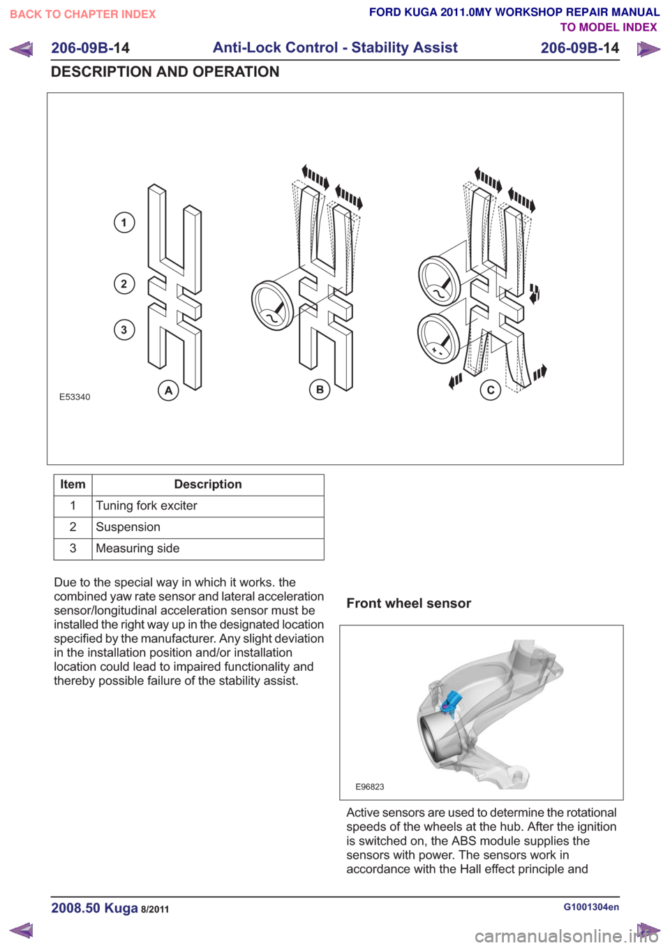
E53340
1
2
3
Description
Item
Tuning fork exciter
1
Suspension
2
Measuring side
3
Due to the special way in which it works. the
combined yaw rate sensor and lateral acceleration
sensor/longitudinal acceleration sensor must be
installed the right way up in the designated location
specified by the manufacturer. Any slight deviation
in the installation position and/or installation
location could lead to impaired functionality and
thereby possible failure of the stability assist.
Front wheel sensor
E96823
Active sensors are used to determine the rotational
speeds of the wheels at the hub. After the ignition
is switched on, the ABS module supplies the
sensors with power. The sensors work in
accordance with the Hall effect principle and
G1001304en2008.50 Kuga8/2011
206-09B- 14
Anti-Lock Control - Stability Assist
206-09B- 14
DESCRIPTION AND OPERATION
TO MODEL INDEX
BACK TO CHAPTER INDEX
FORD KUGA 2011.0MY WORKSHOP REPAIR MANUAL
Page 1443 of 2057
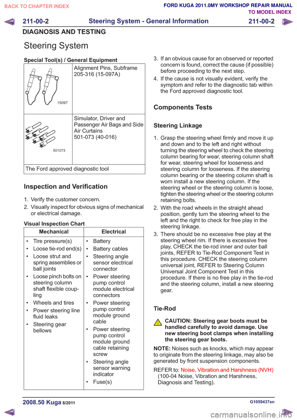
Steering System
Special Tool(s) / General EquipmentAlignment Pins, Subframe
205-316 (15-097A)
15097
Simulator, Driver and
Passenger Air Bags and Side
Air Curtains
501-073 (40-016)
501073
The Ford approved diagnostic tool
Inspection and Verification
1. Verify the customer concern.
2. Visually inspect for obvious signs of mechanicalor electrical damage.
Visual Inspection Chart
Electrical
Mechanical
• Battery
• Battery cables
• Steering anglesensor electrical
connector
• Power steering pump control
module electrical
connectors
• Power steering pump control
module ground
cable
• Power steering pump control
module ground
cable retaining
screw
• Steering angle sensor warning
indicator
• Fuse(s)
• Tire pressure(s)
• Loose tie-rod end(s)
• Loose strut and
spring assemblies or
ball joints
• Loose pinch bolts on steering column
shaft flexible coup-
ling
• Wheels and tires
• Power steering line fluid leaks
• Steering gear bellows 3. If an obvious cause for an observed or reported
concern is found, correct the cause (if possible)
before proceeding to the next step.
4. If the cause is not visually evident, verify the symptom and refer to the diagnostic tab within
the Ford approved diagnostic tool.
Components Tests
Steering Linkage
1. Grasp the steering wheel firmly and move it upand down and to the left and right without
turning the steering wheel to check the steering
column bearing for wear, steering column shaft
for wear, steering wheel for looseness and
steering column for looseness. If the steering
column bearing or the steering column shaft is
worn install a new steering column. If the
steering wheel or the steering column is loose,
tighten the steering wheel or the steering column
retaining bolts.
2. With the road wheels in the straight ahead position, gently turn the steering wheel to the
left and the right to check for free play in the
steering linkage.
3. There should be no excessive free play at the steering wheel rim. If there is excessive free
play, CHECK the tie-rod inner and outer ball
joints, REFER to Tie-Rod Component Test in
this procedure. CHECK the steering column
universal joint, REFER to Steering Column
Universal Joint Component Test in this
procedure. If there is no free play in the tie-rod
and the steering column, install a new steering
gear.
Tie-Rod
CAUTION: Steering gear boots must be
handled carefully to avoid damage. Use
new steering boot clamps when installing
the steering gear boots.
NOTE: Noises such as knocks, which may appear
to originate from the steering linkage, may also be
generated by front suspension components.
REFER to: Noise, Vibration and Harshness (NVH)
(100-04 Noise, Vibration and Harshness,
Diagnosis and Testing).
G1059437en2008.50 Kuga8/2011
211-00- 2
Steering System - General Information
211-00- 2
DIAGNOSIS AND TESTING
TO MODEL INDEX
BACK TO CHAPTER INDEX
FORD KUGA 2011.0MY WORKSHOP REPAIR MANUAL
Page 1461 of 2057
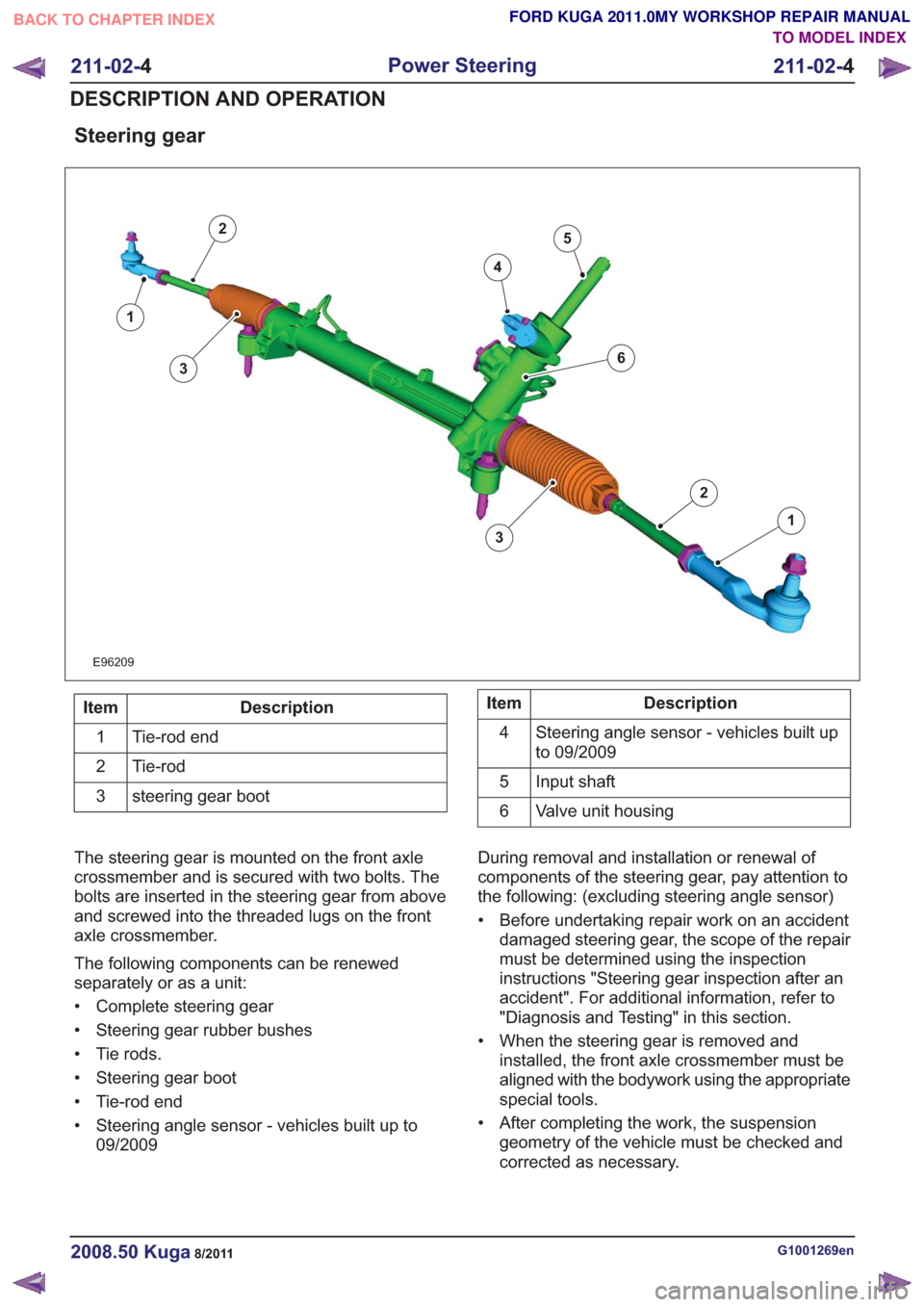
Steering gear
E96209
1
2
3
4
5
1
2
63
Description
Item
Tie-rod end
1
Tie-rod
2
steering gear boot
3Description
Item
Steering angle sensor - vehicles built up
to 09/2009
4
Input shaft
5
Valve unit housing
6
The steering gear is mounted on the front axle
crossmember and is secured with two bolts. The
bolts are inserted in the steering gear from above
and screwed into the threaded lugs on the front
axle crossmember.
The following components can be renewed
separately or as a unit:
• Complete steering gear
• Steering gear rubber bushes
• Tie rods.
• Steering gear boot
• Tie-rod end
• Steering angle sensor - vehicles built up to 09/2009 During removal and installation or renewal of
components of the steering gear, pay attention to
the following: (excluding steering angle sensor)
• Before undertaking repair work on an accident
damaged steering gear, the scope of the repair
must be determined using the inspection
instructions "Steering gear inspection after an
accident". For additional information, refer to
"Diagnosis and Testing" in this section.
• When the steering gear is removed and installed, the front axle crossmember must be
aligned with the bodywork using the appropriate
special tools.
• After completing the work, the suspension geometry of the vehicle must be checked and
corrected as necessary.
G1001269en2008.50 Kuga8/2011
211-02- 4
Power Steering
211-02- 4
DESCRIPTION AND OPERATION
TO MODEL INDEX
BACK TO CHAPTER INDEX
FORD KUGA 2011.0MY WORKSHOP REPAIR MANUAL
Page 1492 of 2057
All vehicles
16.Refer to: Front Toe Adjustment (204-00
Suspension System - General Information,
General Procedures).
G1001271en2008.50 Kuga8/2011
211-02- 35
Power Steering
211-02- 35
REMOVAL AND INSTALLATION
TO MODEL INDEX
BACK TO CHAPTER INDEX
FORD KUGA 2011.0MY WORKSHOP REPAIR MANUAL
Page 1498 of 2057
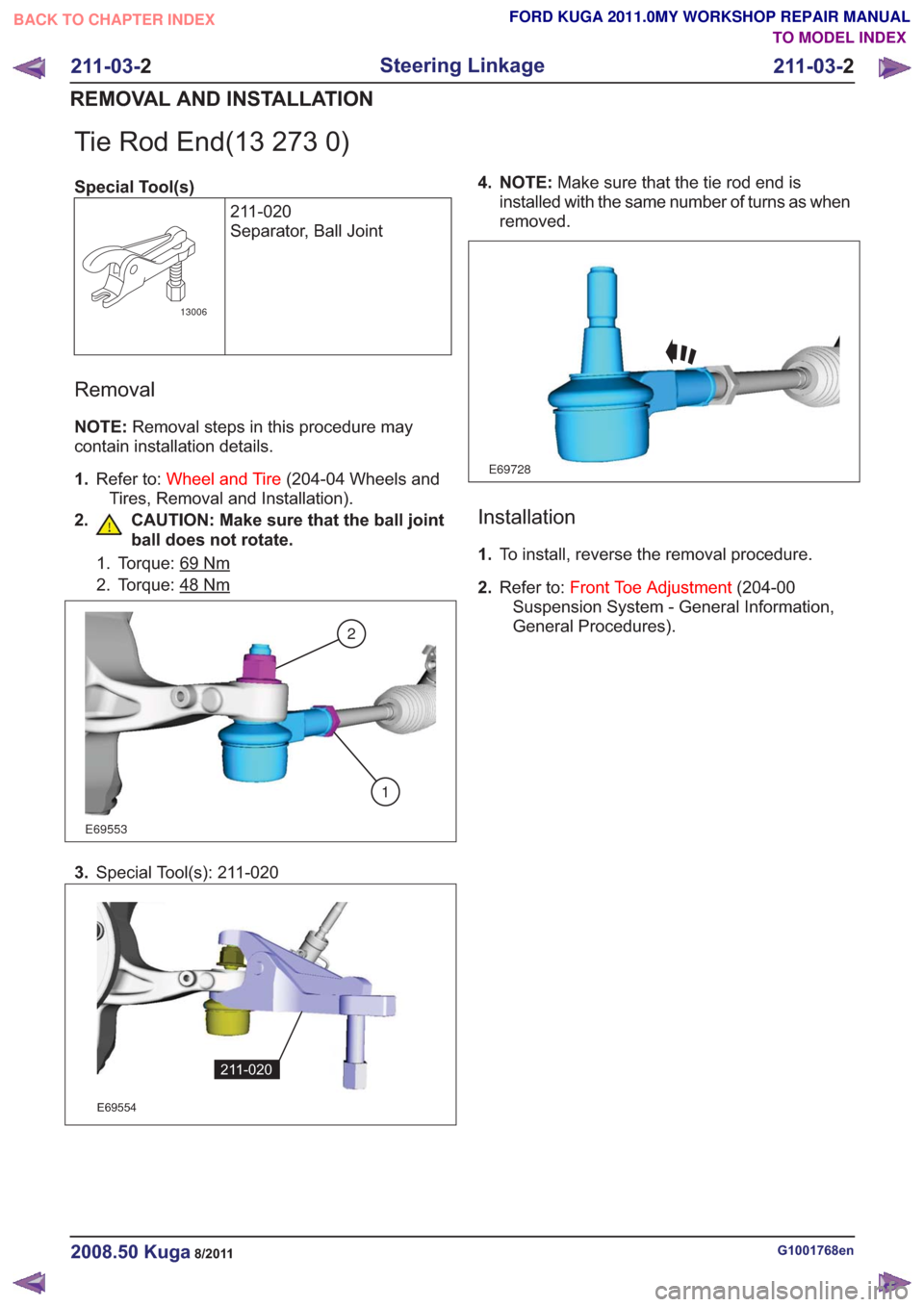
Tie Rod End(13 273 0)
Special Tool(s)211-020
Separator, Ball Joint
13006
Removal
NOTE:Removal steps in this procedure may
contain installation details.
1. Refer to: Wheel and Tire (204-04 Wheels and
Tires, Removal and Installation).
2. CAUTION: Make sure that the ball joint ball does not rotate.
1. Torque: 69Nm
2. Torque: 48Nm
E69553
2
1
3.Special Tool(s): 211-020
E69554
211-020
4. NOTE: Make sure that the tie rod end is
installed with the same number of turns as when
removed.
E69728
Installation
1. To install, reverse the removal procedure.
2. Refer to: Front Toe Adjustment (204-00
Suspension System - General Information,
General Procedures).
G1001768en2008.50 Kuga8/2011
211-03- 2
Steering Linkage
211-03- 2
REMOVAL AND INSTALLATION
TO MODEL INDEX
BACK TO CHAPTER INDEX
FORD KUGA 2011.0MY WORKSHOP REPAIR MANUAL