Page 1532 of 2057

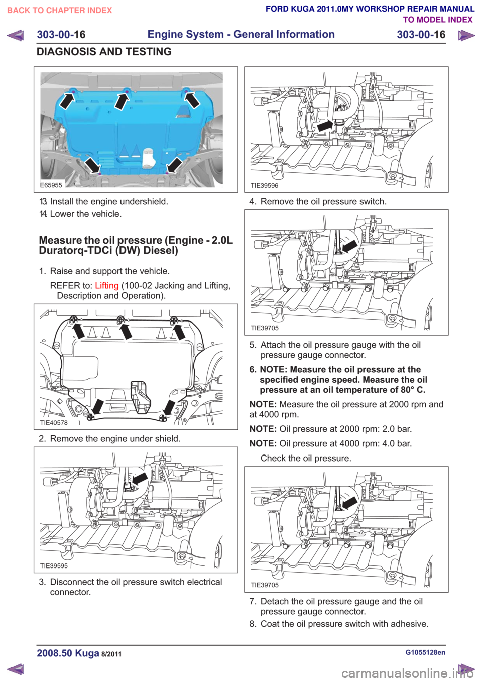
E65955
13. Install the engine undershield.
14. Lower the vehicle.
Measure the oil pressure (Engine - 2.0L
Duratorq-TDCi (DW) Diesel)
1. Raise and support the vehicle.REFER to: Lifting(100-02 Jacking and Lifting,
Description and Operation).
TIE40578
2. Remove the engine under shield.
TIE39595
3. Disconnect the oil pressure switch electrical connector.
TIE39596
4. Remove the oil pressure switch.
TIE39705
5. Attach the oil pressure gauge with the oilpressure gauge connector.
6. NOTE: Measure the oil pressure at the specified engine speed. Measure the oil
pressure at an oil temperature of 80° C.
NOTE: Measure the oil pressure at 2000 rpm and
at 4000 rpm.
NOTE: Oil pressure at 2000 rpm: 2.0 bar.
NOTE: Oil pressure at 4000 rpm: 4.0 bar.
Check the oil pressure.
TIE39705
7. Detach the oil pressure gauge and the oil pressure gauge connector.
8. Coat the oil pressure switch with adhesive.
G1055128en2008.50 Kuga8/2011
303-00-16
Engine System - General Information
303-00- 16
DIAGNOSIS AND TESTING
TO MODEL INDEX
BACK TO CHAPTER INDEX
FORD KUGA 2011.0MY WORKSHOP REPAIR MANUAL
Page 1598 of 2057
25.Refer to: Lifting(100-02 Jacking and Lifting,
Description and Operation).
26. Refer to: Cooling System Draining and Vacuum
Filling (303-03 Engine Cooling, General
Procedures).
27.
E98184
28.
E112511
29. On both sides.
E99722
30mm1
30.
G1191240en2008.50 Kuga8/2011
303-01- 65
Engine— 2.5L Duratec (147kW/200PS) - VI5303-01-
65
REMOVAL
TO MODEL INDEX
BACK TO CHAPTER INDEX
FORD KUGA 2011.0MY WORKSHOP REPAIR MANUAL
Page 1610 of 2057
67. CAUTION: Make sure that nocomponents catch.
Refer to: Lifting(100-02 Jacking and Lifting,
Description and Operation).
68.
70. Special Tool(s): 303-122
General Equipment: Hydraulic Jib Crane
71. Remove the following items:
• General Equipment: Retaining Strap
G1191240en2008.50 Kuga8/2011
303-01- 77
Engine— 2.5L Duratec (147kW/200PS) - VI5303-01-
77
REMOVAL
FORD KUGA 2011.0MY WORKSHOP REPAIR MANUAL
TO MODEL INDEX
BACK TO CHAPTER INDEX
E68472
2
E65770
1
65.69.
E114607
66.
1
2E84187
E84188
303-122
Page 1676 of 2057

Cooling System Draining and Vacuum Filling
General EquipmentCooling System Vacuum Tester and Refiller
Fluid Container
Materials
Specification
Name
WSS-M97B44-D / 4U7J-
19544-AA2A
Antifreeze Super Plus
Premium
Draining
WARNING: When releasing the cooling
system pressure, cover the coolant
expansion tank cap with a thick cloth.
NOTE: Always follow the manufacturer's
instructions when handling the equipment.
1. Refer to: Engine Cooling System Health and
Safety Precautions (100-00 General
Information, Description and Operation).
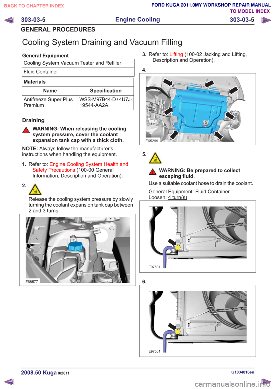
2.
Release the cooling system pressure by slowly
turning the coolant expansion tank cap between
2 and 3 turns.
E68577
3. Refer to: Lifting(100-02 Jacking and Lifting,
Description and Operation).
4.
E65299
5.
WARNING: Be prepared to collect
escaping fluid.
Use a suitable coolant hose to drain the coolant.
General Equipment: Fluid Container
Loosen: 4
turn(s)
E97501
6.
E97501
G1034816en2008.50 Kuga8/2011
303-03- 5
Engine Cooling
303-03- 5
GENERAL PROCEDURES
TO MODEL INDEX
BACK TO CHAPTER INDEX
FORD KUGA 2011.0MY WORKSHOP REPAIR MANUAL
Page 1678 of 2057
Radiator Lower Mounting Repair
General Equipment5mmDrillBit
Cable Ties
Flat File
1. General Equipment: Cable Ties
E100039
2.Refer to: Lifting(100-02 Jacking and Lifting,
Description and Operation).
3.
E98183
4.
E98184
5.
E100040
x4
6. General Equipment: Flat File
1.
2. General Equipment: 5 mm Drill Bit
G1062292en2008.50 Kuga8/2011
303-03- 7
Engine Cooling
303-03- 7
GENERAL PROCEDURES
TO MODEL INDEX
BACK TO CHAPTER INDEX
FORD KUGA 2011.0MY WORKSHOP REPAIR MANUAL
Page 1682 of 2057
Cooling Fan Motor and Shroud — 2.5L Duratec (147kW/200PS)- VI5(24 222 0)
Removal
NOTE: Removal steps in this procedure may
contain installation details.
1. Refer to: Lifting(100-02 Jacking and Lifting,
Description and Operation).
2.
E98183
3.
E98184
4.
E112584
5.
E112335
6. Torque: 25Nm
G1156382en2008.50 Kuga8/2011
303-03- 11
Engine Cooling
303-03- 11
REMOVAL AND INSTALLATION
TO MODEL INDEX
BACK TO CHAPTER INDEX
FORD KUGA 2011.0MY WORKSHOP REPAIR MANUAL
Page 1727 of 2057

Turbocharger(23 612 0)
General EquipmentCable Ties
Hose Clamp Remover/Installer
Materials
Specification
Name
SA-M1C9107-A / YS5J-
M1C9107-AA
Grease KS-PS
Removal
NOTE:
Removal steps in this procedure may
contain installation details.
1. Refer to: Battery Disconnect and Connect
(414-01 Battery, Mounting and Cables,
General Procedures).
2. Refer to: Cooling System Draining and Vacuum
Filling (303-03 Engine Cooling, General
Procedures).
3. Refer to: Cowl Panel Grille (501-02 Front End
Body Panels, Removal and Installation).
4.
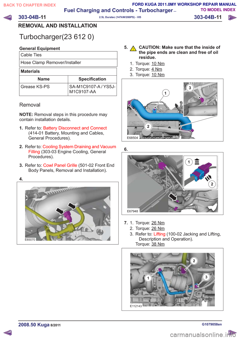
E65070
5. CAUTION: Make sure that the inside of the pipe ends are clean and free of oil
residue.
1. Torque: 10Nm
2. Torque: 4Nm
3. Torque: 10Nm
2
1
3
E68504
6.
E67948
2
1
7.Torque: 26Nm1.
2. Torque: 26
Nm
3. Refer to: Lifting(100-02 Jacking and Lifting,
Description and Operation).
Torque: 38
Nm
E112143
3
2
1
G1079058en2008.50 Kuga8/2011
303-04B- 11
Fuel Charging and Controls - Turbocharger
—
2.5L Duratec (147kW/200PS) - VI5
303-04B- 11
REMOVAL AND INSTALLATION
TO MODEL INDEX
BACK TO CHAPTER INDEX
FORD KUGA 2011.0MY WORKSHOP REPAIR MANUAL
Page 1772 of 2057
Charge Air Cooler(23 620 0)
Removal
NOTE:Removal steps in this procedure may
contain installation details.
1. Refer to: Lifting(100-02 Jacking and Lifting,
Description and Operation).
2.
E98183
E98184
4. Torque: 5Nm
E99948
Installation
1.To install, reverse the removal.
G1079096en2008.50 Kuga8/2011
303-12- 8
Intake Air Distribution and Filtering
— 2.5L Duratec
(147kW/200PS) - VI5
303-12- 8
REMOVAL AND INSTALLATION
FORD KUGA 2011.0MY WORKSHOP REPAIR MANUAL
TO MODEL INDEX
BACK TO CHAPTER INDEX
3.