Page 1288 of 2057
1.Refer to: Health and Safety Precautions (100-00
General Information, Description and
Operation).
2. Refer to: Lifting(100-02 Jacking and Lifting,
Description and Operation).
3.
E114257
4. WARNING: Be prepared to collect escaping fluid.
E124748
5.
E124778
6. WARNING: Be prepared to collectescaping fluid.
x2x2
E124749
7.
E128365
G1268328en2008.50 Kuga8/2011
205-02- 43
Rear Drive Axle/Differential
205-02- 43
DISASSEMBLY AND ASSEMBLY
TO MODEL INDEX
BACK TO CHAPTER INDEX
FORD KUGA 2011.0MY WORKSHOP REPAIR MANUAL
Page 1301 of 2057
2.Refer to: Lifting(100-02 Jacking and Lifting,
Description and Operation).
Refer to: Wheel and Tire (204-04 Wheels and
Tires, Removal and Installation).
3. NOTE: This step is only necessary when
installing a new component.
E99269
4.
E101039
5. WARNING: Make sure that no load is placed on the brake hose.
E100801
G1076961en2008.50 Kuga8/2011
205-04- 6
Front Drive Halfshafts
205-04- 6
REMOVAL AND INSTALLATION
TO MODEL INDEX
BACK TO CHAPTER INDEX
FORD KUGA 2011.0MY WORKSHOP REPAIR MANUAL
Page 1311 of 2057
Front Halfshaft RH — LHD 4WD/RHD 4WD(14 321 0)
Special Tool(s) / General Equipment204-159
Lever, Wheel Knuckle
14039
204-602
Installer, Halfshaft
E62067
204-605
Separator, Lower Arm Ball
Joint
E63772
204-609
Protection Cap, Ball Joint
Gaiter
E75372
205-071-01
Adapter for 205-071 (Thrust
Pad)
15026A01
211-020
Separator, Ball Joint
13006
Puller
Removal
1. NOTE:This step is only necessary when
installing a new component.
E99184
2. Refer to: Lifting(100-02 Jacking and Lifting,
Description and Operation).
Refer to: Wheel and Tire (204-04 Wheels and
Tires, Removal and Installation).
3. NOTE: This step is only necessary when
installing a new component.
E102112
G1076962en2008.50 Kuga8/2011
205-04- 16
Front Drive Halfshafts
205-04- 16
REMOVAL AND INSTALLATION
TO MODEL INDEX
BACK TO CHAPTER INDEX
FORD KUGA 2011.0MY WORKSHOP REPAIR MANUAL
Page 1330 of 2057
Rear Halfshaft
Special Tool(s) / General Equipment308-759
Remover, Rear Driveshaft
E100143
Cable Ties
Special Tool(s) / General EquipmentTire Lever
Transmission Jack
Materials
Specification
Name
WSK-M2G349-A8 /
9U7J-M2G349-AA
Sealant LGN
Removal
1.
On both sides.
Refer to: Wheel and Tire (204-04 Wheels and
Tires, Removal and Installation).
2. On both sides.
E101661
3.Refer to: Lifting(100-02 Jacking and Lifting,
Description and Operation).
4. WARNING: Make sure that no load is placed on the brake hose.
On both sides.
General Equipment: Cable Ties
E100132
5.On both sides.
Refer to: Spring(204-02 Rear Suspension,
Removal and Installation).
6. On both sides.
x4x4
E101639
7.On both sides.
E101640
G1058429en2008.50 Kuga8/2011
205-05- 2
Rear Drive Halfshafts
205-05- 2
REMOVAL AND INSTALLATION
TO MODEL INDEX
BACK TO CHAPTER INDEX
FORD KUGA 2011.0MY WORKSHOP REPAIR MANUAL
Page 1355 of 2057

too close to the fluid level indicator assembly,
or float assembly damage.
Bypass Condition Test
1. Check the fluid in the brake master cylinderreservoir. Fill the brake master cylinder reservoir
if low or empty.
2. Observe the fluid level in the brake master cylinder reservoir. If after several brake
applications, the fluid level remains the same,
measure the wheel turning torque required to
rotate the wheels with the brakes applied as
follows:
Place the transaxle in the NEUTRAL position.
Raise and support the vehicle. REFER to: (100-02
Jacking and Lifting) Jacking (Description and Operation),
Lifting (Description and Operation).
Apply the brakes with a minimum of 445 N (100
lb) and hold for approximately 15 seconds. With
the brakes still applied, exert a torque on the front
wheels of 10.1 Nm (75 lb ft). If either wheel rotates,
install a new brake master cylinder.
REFER to: Brake Master Cylinder - 2.5L Duratec
(147kW/200PS) - VI5 (206-06 Hydraulic Brake
Actuation, Removal and Installation).
Non-Pressure Leaks
Any empty brake master cylinder reservoir
condition may be caused by two types of
non-pressure external leaks.
Type 1: An external leak may occur at the brake
master cylinder reservoir cap because of incorrect
positioning of the gasket and cap. Reposition the
cap and gasket.
Type 2: An external leak may occur at the brake
master cylinder reservoir mounting seals. Service
such a leak by installing new seals.
G1058975en2008.50 Kuga8/2011
206-00- 19
Brake System - General Information
206-00- 19
DIAGNOSIS AND TESTING
TO MODEL INDEX
BACK TO CHAPTER INDEX
FORD KUGA 2011.0MY WORKSHOP REPAIR MANUAL
Page 1368 of 2057
Brake System Draining and Filling(12 154 0; 12 154 4)
General EquipmentFluid Container
Draining
15. Refer to: Brake System Health and Safety
Precautions (100-00 General Information,
Description and Operation).
16.
E86914
17. Refer to: Lifting(100-02 Jacking and Lifting,
Description and Operation).
18. On both sides.
E139455
19.On both sides.
General Equipment: Fluid Container
E139454
20.On both sides.
Loosen: 180°
G1420093en2008.50 Kuga8/2011
206-00- 32
Brake System - General Information
206-00- 32
GENERAL PROCEDURES
TO MODEL INDEX
BACK TO CHAPTER INDEX
FORD KUGA 2011.0MY WORKSHOP REPAIR MANUAL
Page 1388 of 2057

Pinpoint Tests
PINPOINT TEST A : THE PARKING BRAKE WILL NOT APPLY
DETAILS/RESULTS/ACTIONS
TEST CONDITIONS
A1: CHECK PARKING BRAKE CABLE ADJUSTMENT
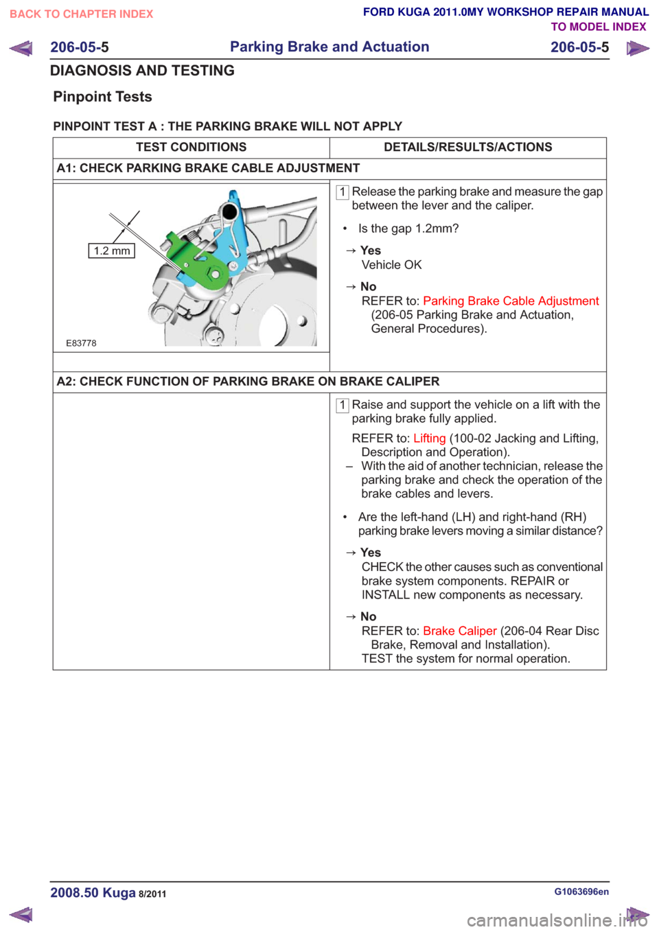
1 Release the parking brake and measure the gap
between the lever and the caliper.
• Is the gap 1.2mm?
zYe s
E83778
1.2 mm
Vehicle OK
zNo REFER to: Parking Brake Cable Adjustment
(206-05 Parking Brake and Actuation,
General Procedures).
A2: CHECK FUNCTION OF PARKING BRAKE ON BRAKE CALIPER
1 Raise and support the vehicle on a lift with the
parking brake fully applied.
REFER to:
Lifting(100-02 Jacking and Lifting,
Description and Operation).
– With the aid of another technician, release the parking brake and check the operation of the
brake cables and levers.
• Are the left-hand (LH) and right-hand (RH) parking brake levers moving a similar distance?
zYe s
CHECK the other causes such as conventional
brake system components. REPAIR or
INSTALL new components as necessary.
zNoREFER to: Brake Caliper (206-04 Rear Disc
Brake, Removal and Installation).
TEST the system for normal operation.
G1063696en2008.50 Kuga8/2011
206-05- 5
Parking Brake and Actuation
206-05- 5
DIAGNOSIS AND TESTING
TO MODEL INDEX
BACK TO CHAPTER INDEX
FORD KUGA 2011.0MY WORKSHOP REPAIR MANUAL
Page 1393 of 2057

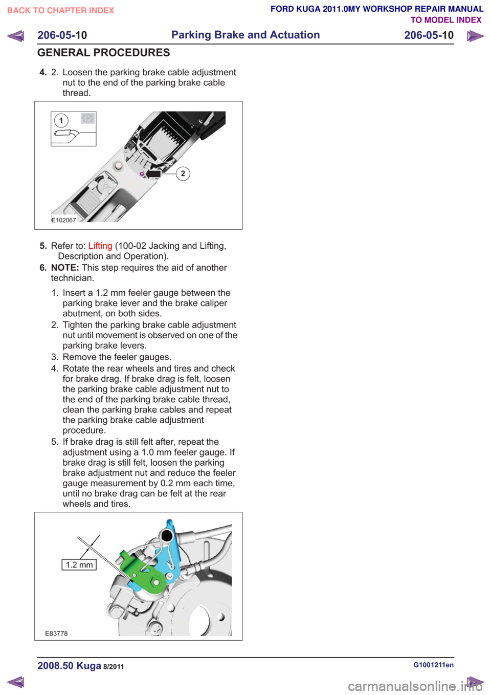
4.Loosen the parking brake cable adjustment
nut to the end of the parking brake cable
thread.
2.
E102067
2
P1
5.
Refer to: Lifting(100-02 Jacking and Lifting,
Description and Operation).
6. NOTE: This step requires the aid of another
technician.
1. Insert a 1.2 mm feeler gauge between the parking brake lever and the brake caliper
abutment, on both sides.
2. Tighten the parking brake cable adjustment nut until movement is observed on one of the
parking brake levers.
3. Remove the feeler gauges.
4. Rotate the rear wheels and tires and check for brake drag. If brake drag is felt, loosen
the parking brake cable adjustment nut to
the end of the parking brake cable thread,
clean the parking brake cables and repeat
the parking brake cable adjustment
procedure.
5. If brake drag is still felt after, repeat the adjustment using a 1.0 mm feeler gauge. If
brake drag is still felt, loosen the parking
brake adjustment nut and reduce the feeler
gauge measurement by 0.2 mm each time,
until no brake drag can be felt at the rear
wheels and tires.
E83778
1.2 mm
G1001211en2008.50 Kuga8/2011
206-05- 10
Parking Brake and Actuation
206-05- 10
GENERAL PROCEDURES
TO MODEL INDEX
BACK TO CHAPTER INDEX
FORD KUGA 2011.0MY WORKSHOP REPAIR MANUAL