2011 FORD KUGA general procedures
[x] Cancel search: general proceduresPage 388 of 2057

Module Configuration
Activation
1.
Install the most up-to-date software version in
the integrated diagnostic system (IDS).
2. In IDS, select the "Module reprogramming"
submenu in the "Module programming" menu
tool box and then follow the instructions.
3. Transfer a new software version (if available)
to the powertrain control module (PCM) using
IDS, if a module-reprogramming of the PCM
may be required in the case of engine running
concerns.
4. Following installation of a wheel/tire
combination, for which the tire-tread
circumference does not correspond to that of
standard tires, the tire size must be changed in
the PCM using IDS. Therefore select the
"Programmable parameters" submenu and enter
the corresponding tire size under the "tire size"
menu item. G1158256en
2008.50 Kuga 8/2011 418-01-2
Module Configuration
418-01-2
GENERAL PROCEDURESTO MODEL INDEX
BACK TO CHAPTER INDEX
FORD KUGA 2011.0MY WORKSHOP REPAIR MANUAL
Page 389 of 2057

Programmable Module Installation
Activation
5.
Install the most up-to-date software version in
IDS.
6. If, before replacing a module, it was not possible
to read out the vehicle-specific data using the
integrated diagnostic system (IDS) (the module
to be replaced does not respond) then, during
programming of the new module, the
vehicle-specific data must be entered manually
via a selection list in IDS or via a code which
can be obtained from the Technical Hotline.
7. In order to program, select the "Install
programmable module" submenu in the "Module
programming" menu tool box and then follow
the instructions.
8. The following modules must be programmed
after replacement:
•
• Anti-lock braking system module (ABS)
• Audio system module (ACM)
• CD player (CDP)
• Driver's door control unit (D-DCU)
• Passenger's door control unit (P-DCU)
• Rear left door control unit (RL-DCU)
• Rear right door control unit (RR-DCU)
• Electrical power steering (EPS)
• Generic Display Module (GDM) (vehicles
with DVD navigation system with
touchscreen)
• Generic electronic module (GEM)
• Headlamp control module (HCM) (vehicles with gas discharge headlamps)
• Instrument cluster (IC)
• Navigation system (NAV) (vehicles with navigation system)
• Parking aid module(PAM)
• Powertrain control module (PCM)
• Restraint control module (RCM)
• Rear entertainment system module (RETM) (vehicles with rear seat entertainment
system)
9. In order to configure the PCM, select the
"Programmable parameters" submenu in the
"Module programming" menu tool box and then
follow the instructions.
10. For vehicles with anti-lock braking system and
electronic stability program, these must also be configured using IDS following replacement of
the lateral acceleration sensor, yaw rate sensor
or pressure sensor. Configuration is performed
in the "Programmable parameters" menu tool
box.
G1158258en
2008.50 Kuga 8/2011 418-01-3
Module Configuration
418-01-3
GENERAL PROCEDURESTO MODEL INDEX
BACK TO CHAPTER INDEX
FORD KUGA 2011.0MY WORKSHOP REPAIR MANUAL
Page 464 of 2057

Generic Electronic Module (GEM)
General Equipment
Ford Diagnostic Equipment
Removal
CAUTIONS: Modules must not be swapped between
vehicles.
Compare the number of relays and fuses
in the defective GEM and the new GEM.
Transfer from the defective GEM any relays
and fuses which are not in the new GEM.
In doing so, pay attention that fuses with
the correct Ampere rating are used, by
referring to the wiring diagrams.
When installing a new GEM on vehicles
with a diesel engine, make sure that a fuel
pump fuse (F111) with 5A is used.
When installing a new GEM on vehicles
with a petrol engine, make sure that a fuel
pump fuse (F111) with 15A is used.
NOTE: GEM is integrated into the central junction
box (CJB) and cannot be removed individually.
1. NOTE: This step is only necessary when
installing a new component.
Upload the GEM configuration information using
the Programmable Modules Installation Routine.
General Equipment: Ford Diagnostic Equipment
2. Refer to: Battery Disconnect and Connect
(414-01 Battery, Mounting and Cables,
General Procedures).
3. 4.
5.
Installation
1.
To install, reverse the removal procedure.
2. NOTE: This step is only necessary when
installing a new component.
Download the GEM configuration information
to the newly installed GEM using the
programmable modules installation routine.
3. NOTE: This step is only necessary when
installing a new component.
Program all keys using the Key Programming
Routine.
General Equipment: Ford Diagnostic Equipment G1065605en
2008.50 Kuga 8/2011 419-10-14
Multifunction Electronic Modules
419-10-14
REMOVAL AND INSTALLATIONTO MODEL INDEX
BACK TO CHAPTER INDEX
FORD KUGA 2011.0MY WORKSHOP REPAIR MANUALE51159 122E102019 E102020
Page 466 of 2057

Calibrate the headlamp leveling system.
General Equipment: Ford Diagnostic Equipment
4. NOTE: This step is only necessary when
installing a new component.
Refer to: Headlamp Adjustment (417-01 Exterior
Lighting, General Procedures). G1076572en
2008.50 Kuga 8/2011 419-10-16
Multifunction Electronic Modules
419-10-16
REMOVAL AND INSTALLATIONTO MODEL INDEX
BACK TO CHAPTER INDEX
FORD KUGA 2011.0MY WORKSHOP REPAIR MANUAL
Page 1158 of 2057

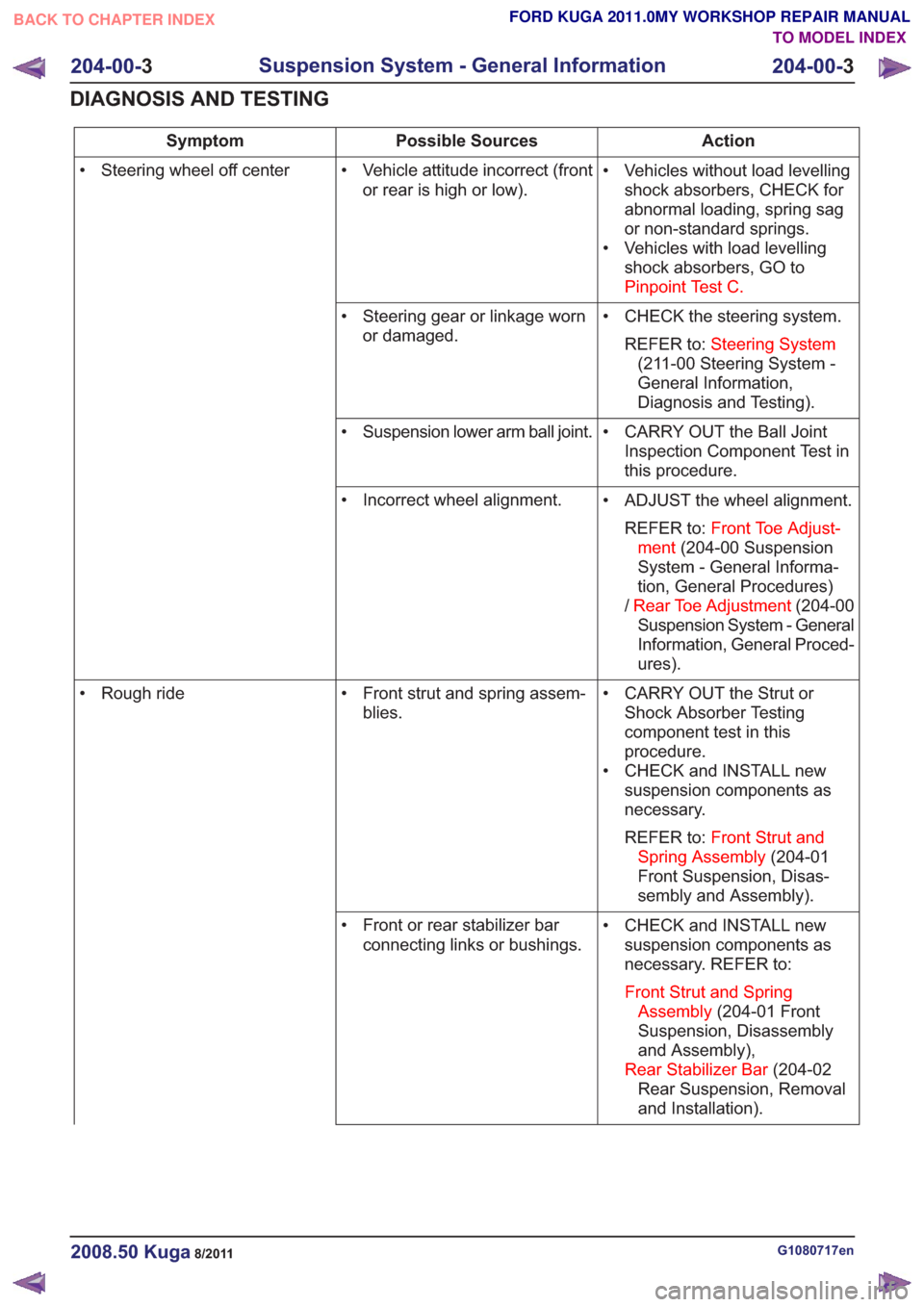
Action
Possible Sources
Symptom
• Vehicles without load levellingshock absorbers, CHECK for
abnormal loading, spring sag
or non-standard springs.
• Vehicles with load levelling shock absorbers, GO to
Pinpoint Test C.
• Vehicle attitude incorrect (front
or rear is high or low).
• Steering wheel off center
• CHECK the steering system.REFER to: Steering System
(211-00 Steering System -
General Information,
Diagnosis and Testing).
• Steering gear or linkage worn
or damaged.
• CARRY OUT the Ball JointInspection Component Test in
this procedure.
• Suspension lower arm ball joint.
• ADJUST the wheel alignment.REFER to: Front Toe Adjust-
ment (204-00 Suspension
System - General Informa-
tion, General Procedures)
/ Rear Toe Adjustment (204-00
Suspension System - General
Information, General Proced-
ures).
• Incorrect wheel alignment.
• CARRY OUT the Strut orShock Absorber Testing
component test in this
procedure.
• CHECK and INSTALL new suspension components as
necessary.
REFER to: Front Strut and
Spring Assembly (204-01
Front Suspension, Disas-
sembly and Assembly).
• Front strut and spring assem-
blies.
• Rough ride
• CHECK and INSTALL newsuspension components as
necessary. REFER to:
Front Strut and Spring Assembly (204-01 Front
Suspension, Disassembly
and Assembly),
Rear Stabilizer Bar (204-02
Rear Suspension, Removal
and Installation).
• Front or rear stabilizer bar
connecting links or bushings.
G1080717en2008.50 Kuga8/2011
204-00- 3
Suspension System - General Information
204-00- 3
DIAGNOSIS AND TESTING
TO MODEL INDEX
BACK TO CHAPTER INDEX
FORD KUGA 2011.0MY WORKSHOP REPAIR MANUAL
Page 1159 of 2057

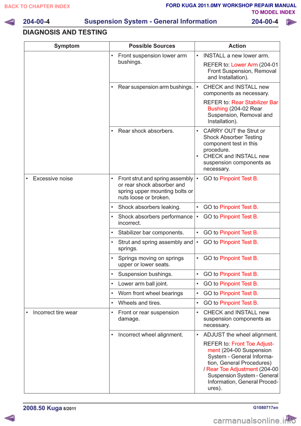
Action
Possible Sources
Symptom
• INSTALL a new lower arm.REFER to: Lower Arm (204-01
Front Suspension, Removal
and Installation).
• Front suspension lower arm
bushings.
• CHECK and INSTALL newcomponents as necessary.
REFER to: Rear Stabilizer Bar
Bushing (204-02 Rear
Suspension, Removal and
Installation).
• Rear suspension arm bushings.
• CARRY OUT the Strut orShock Absorber Testing
component test in this
procedure.
• CHECK and INSTALL new suspension components as
necessary.
• Rear shock absorbers.
• GO toPinpoint Test B.
• Front strut and spring assembly
or rear shock absorber and
spring upper mounting bolts or
nuts loose or broken.
• Excessive noise
• GO toPinpoint Test B.
• Shock absorbers leaking.
• GO toPinpoint Test B.
• Shock absorbers performance
incorrect.
• GO toPinpoint Test B.
• Stabilizer bar components.
• GO toPinpoint Test B.
• Strut and spring assembly and
springs.
• GO toPinpoint Test B.
• Springs moving on springs
upper or lower seats.
• GO toPinpoint Test B.
• Suspension bushings.
• GO toPinpoint Test B.
• Lower arm ball joint.
• GO toPinpoint Test B.
• Worn front wheel bearings
• GO toPinpoint Test B.
• Wheels and tires.
• CHECK and INSTALL newsuspension components as
necessary.
• Front or rear suspension
damage.
• Incorrect tire wear
• ADJUST the wheel alignment.REFER to: Front Toe Adjust-
ment (204-00 Suspension
System - General Informa-
tion, General Procedures)
/ Rear Toe Adjustment (204-00
Suspension System - General
Information, General Proced-
ures).
• Incorrect wheel alignment.
G1080717en2008.50 Kuga8/2011
204-00-
4
Suspension System - General Information
204-00- 4
DIAGNOSIS AND TESTING
TO MODEL INDEX
BACK TO CHAPTER INDEX
FORD KUGA 2011.0MY WORKSHOP REPAIR MANUAL
Page 1161 of 2057

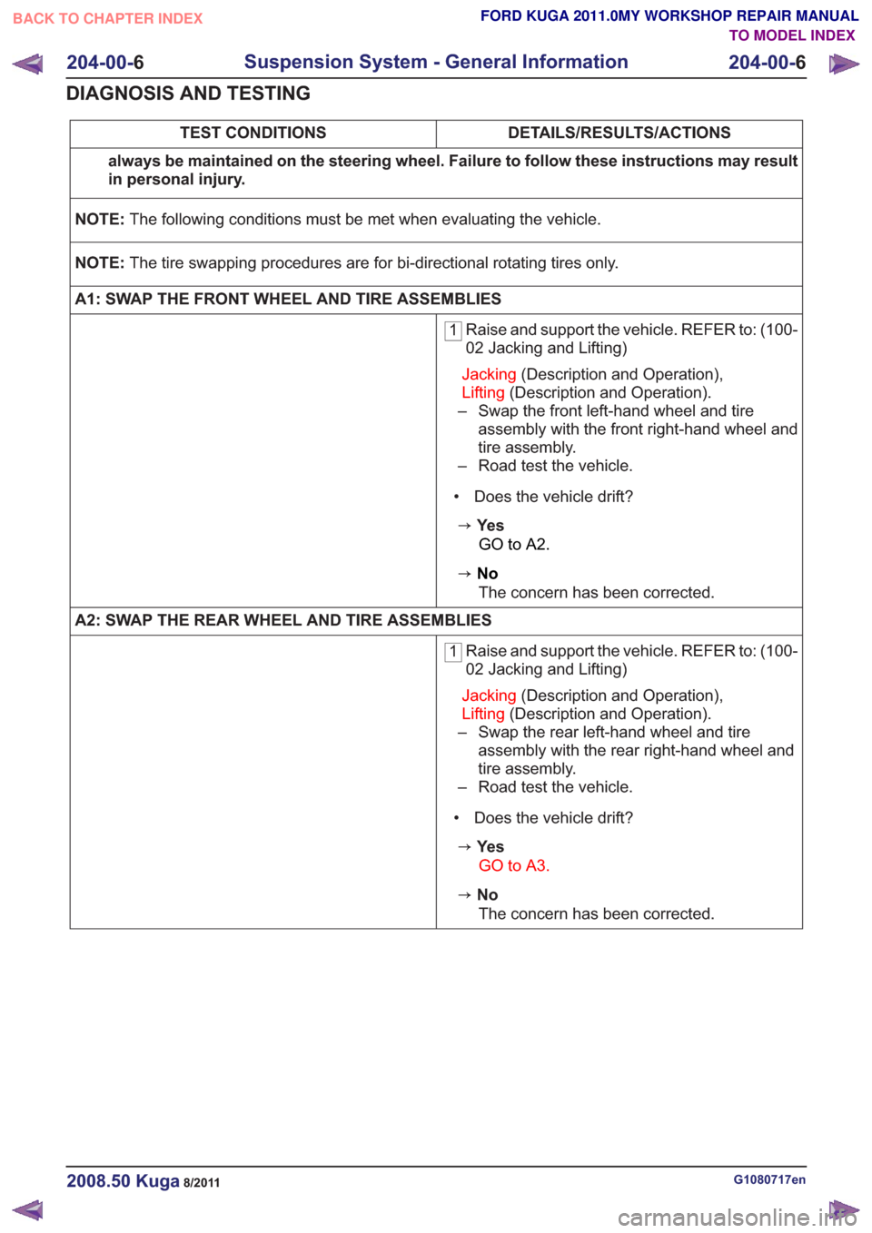
DETAILS/RESULTS/ACTIONS
TEST CONDITIONS
always be maintained on the steering wheel. Failure to follow these instructions may result
in personal injury.
NOTE: The following conditions must be met when evaluating the vehicle.
NOTE: The tire swapping procedures are for bi-directional rotating tires only.
A1: SWAP THE FRONT WHEEL AND TIRE ASSEMBLIES
1 Raise and support the vehicle. REFER to: (100-
02 Jacking and Lifting)
Jacking (Description and Operation),
Lifting (Description and Operation).
– Swap the front left-hand wheel and tire assembly with the front right-hand wheel and
tire assembly.
– Road test the vehicle.
• Does the vehicle drift?
zYe s GO to A2.
zNoThe concern has been corrected.
A2: SWAP THE REAR WHEEL AND TIRE ASSEMBLIES
1 Raise and support the vehicle. REFER to: (100-
02 Jacking and Lifting)
Jacking (Description and Operation),
Lifting (Description and Operation).
– Swap the rear left-hand wheel and tire assembly with the rear right-hand wheel and
tire assembly.
– Road test the vehicle.
• Does the vehicle drift?
zYe s GO to A3.
zNoThe concern has been corrected.
G1080717en2008.50 Kuga8/2011
204-00- 6
Suspension System - General Information
204-00- 6
DIAGNOSIS AND TESTING
TO MODEL INDEX
BACK TO CHAPTER INDEX
FORD KUGA 2011.0MY WORKSHOP REPAIR MANUAL
Page 1168 of 2057

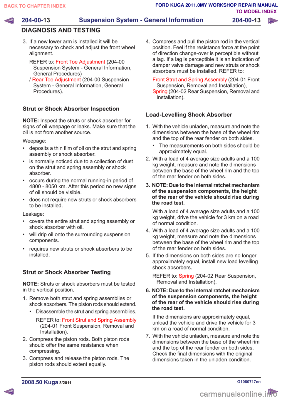
3. If a new lower arm is installed it will benecessary to check and adjust the front wheel
alignment.
REFER to: Front Toe Adjustment (204-00
Suspension System - General Information,
General Procedures)
/ Rear Toe Adjustment (204-00 Suspension
System - General Information, General
Procedures).
Strut or Shock Absorber Inspection
NOTE: Inspect the struts or shock absorber for
signs of oil weepage or leaks. Make sure that the
oil is not from another source.
Weepage:
• deposits a thin film of oil on the strut and spring assembly or shock absorber.
• is normally noticed due to a collection of dust on the strut and spring assembly or shock
absorber.
• occurs during the normal running-in period of 4800 - 8050 km. After this period no new signs
of oil should be visible.
• does not require new struts or shock absorbers to be installed.
Leakage:
• covers the entire strut and spring assembly or shock absorber with oil.
• will drip oil onto the surrounding suspension components.
• requires new struts or shock absorbers to be installed.
Strut or Shock Absorber Testing
NOTE: Struts or shock absorbers must be tested
in the vertical position.
1. Remove both strut and spring assemblies or shock absorbers. The piston rods should extend.
• Disassemble the strut and spring assemblies.
REFER to: Front Strut and Spring Assembly
(204-01 Front Suspension, Removal and
Installation).
2. Compress the piston rods. Both piston rods should offer the same resistance when
compressing.
3. Compress and release the piston rods. The piston rods should extent equally. 4. Compress and pull the piston rod in the vertical
position. Feel if the resistance force at the point
of direction change-over is perceptible without
a lag. If a lag is perceptible it is an indication of
damper valve damage and new struts or shock
absorbers must be installed. REFER to:
Front Strut and Spring Assembly (204-01 Front
Suspension, Removal and Installation),
Spring (204-02 Rear Suspension, Removal and
Installation).
Load-Levelling Shock Absorber
1. With the vehicle unladen, measure and note the dimensions between the base of the wheel rim
and the top of the rear fender on both sides.
• The measurements on both sides should be approximately equal.
2. With a load of 4 average size adults and a 100 kg weight, measure and note the dimensions
between the base of the wheel rim and the top
of the rear fender on both sides.
3. NOTE: Due to the internal ratchet mechanism of the suspension components, the height
of the rear of the vehicle should rise during
the road test.
With a load of 4 average size adults and a 100
kg weight, drive the vehicle for 3 km on a road
of normal condition.
4. With a load of 4 average size adults and a 100 kg weight, measure and note the dimensions
between the base of the wheel rim and the top
of the rear fender on both sides.
5. If the dimensions on both sides are no longer approximately equal, install new load levelling
shock absorbers.
REFER to: Spring(204-02 Rear Suspension,
Removal and Installation).
6. NOTE: Due to the internal ratchet mechanism of the suspension components, the height
of the rear of the vehicle should rise during
the road test.
If the dimensions are approximately equal,
unload the vehicle and drive the vehicle for 3
km on a road of normal condition.
7. With the vehicle unladen, measure and note the dimensions between the base of the wheel rim
and the top of the rear fender on both sides.
Check the final dimensions with the original
dimensions taken in the unladen condition.
G1080717en2008.50 Kuga8/2011
204-00- 13
Suspension System - General Information
204-00- 13
DIAGNOSIS AND TESTING
TO MODEL INDEX
BACK TO CHAPTER INDEX
FORD KUGA 2011.0MY WORKSHOP REPAIR MANUAL