Page 1551 of 2057
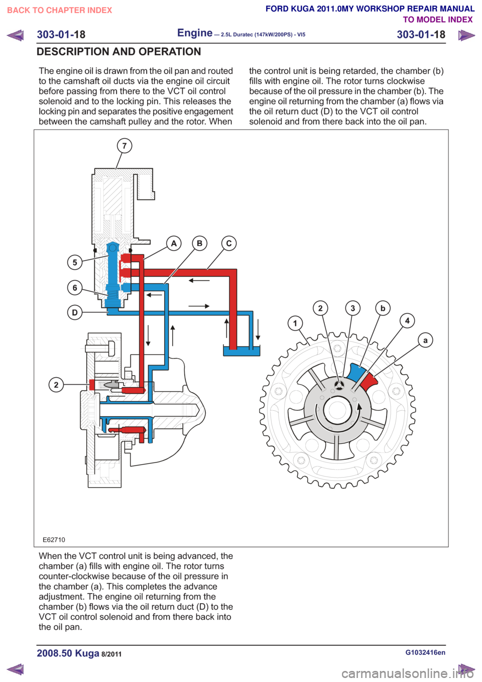
The engine oil is drawn from the oil pan and routed
to the camshaft oil ducts via the engine oil circuit
before passing from there to the VCT oil control
solenoid and to the locking pin. This releases the
locking pin and separates the positive engagement
between the camshaft pulley and the rotor. Whenthe control unit is being retarded, the chamber (b)
fills with engine oil. The rotor turns clockwise
because of the oil pressure in the chamber (b). The
engine oil returning from the chamber (a) flows via
the oil return duct (D) to the VCT oil control
solenoid and from there back into the oil pan.
E62710
When the VCT control unit is being advanced, the
chamber (a) fills with engine oil. The rotor turns
counter-clockwise because of the oil pressure in
the chamber (a). This completes the advance
adjustment. The engine oil returning from the
chamber (b) flows via the oil return duct (D) to the
VCT oil control solenoid and from there back into
the oil pan.
G1032416en2008.50 Kuga8/2011
303-01-
18
Engine— 2.5L Duratec (147kW/200PS) - VI5303-01-
18
DESCRIPTION AND OPERATION
TO MODEL INDEX
BACK TO CHAPTER INDEX
FORD KUGA 2011.0MY WORKSHOP REPAIR MANUAL
Page 1553 of 2057
Intake Manifold(21 183 0)
Removal
NOTE:Removal steps in this procedure may
contain installation details.
1. Refer to: Fuel System Pressure Release
(310-00 Fuel System - General Information,
General Procedures).
2. Refer to: Battery Disconnect and Connect
(414-01 Battery, Mounting and Cables,
General Procedures).
3. Refer to: Air Cleaner (303-12 Intake Air
Distribution and Filtering - 2.5L Duratec
(147kW/200PS) - VI5, Removal and
Installation).
4.
E65070
5. CAUTION: Make sure that the inside of the pipe ends are clean and free of oil
residue.
1. Torque: 10Nm
2. Torque: 4Nm
3. Torque: 10Nm
2
1
3
E68504
6.
E67375
7.
E68413
8.Torque: 10Nm
E67741
G1079020en2008.50 Kuga8/2011
303-01- 20
Engine— 2.5L Duratec (147kW/200PS) - VI5303-01-
20
REMOVAL AND INSTALLATION
TO MODEL INDEX
BACK TO CHAPTER INDEX
FORD KUGA 2011.0MY WORKSHOP REPAIR MANUAL
Page 1583 of 2057
Cylinder Head(21 163 0)
General EquipmentFluid Container
Tire Lever
Materials
Specification
Name
WSS-M2C913-C
Engine Oil - 5W-30
SA-M1C9107-A / YS5J-
M1C9107-AA
Grease KS-PS
Removal
NOTE:
Removal steps in this procedure may
contain installation details.
1. Refer to: Cooling System Draining and Vacuum
Filling (303-03 Engine Cooling, General
Procedures).
2. Refer to: Fuel System Pressure Release
(310-00 Fuel System - General Information,
General Procedures).
3. Refer to: Battery Disconnect and Connect
(414-01 Battery, Mounting and Cables,
General Procedures).
4. Refer to: Air Cleaner (303-12 Intake Air
Distribution and Filtering - 2.5L Duratec
(147kW/200PS) - VI5, Removal and
Installation).
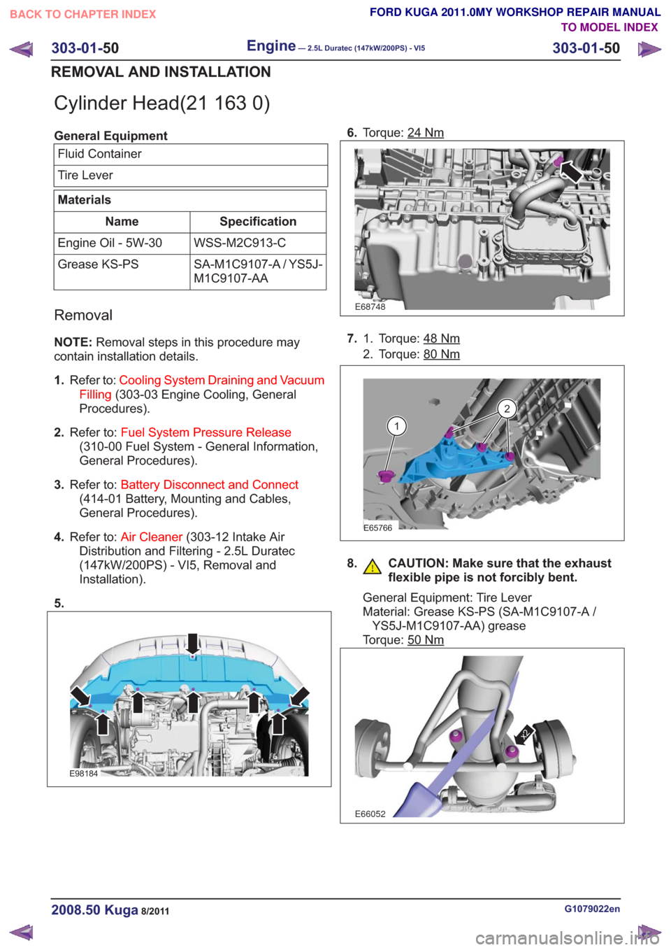
5.
E98184
6. Torque: 24Nm
E68748
7. Torque: 48Nm1.
2. Torque: 80
Nm
E65766
1
2
8. CAUTION: Make sure that the exhaust
flexible pipe is not forcibly bent.
General Equipment: Tire Lever
Material: Grease KS-PS (SA-M1C9107-A /YS5J-M1C9107-AA) grease
Torque: 50
Nm
E66052
x2
G1079022en2008.50 Kuga8/2011
303-01- 50
Engine— 2.5L Duratec (147kW/200PS) - VI5303-01-
50
REMOVAL AND INSTALLATION
TO MODEL INDEX
BACK TO CHAPTER INDEX
FORD KUGA 2011.0MY WORKSHOP REPAIR MANUAL
Page 1697 of 2057
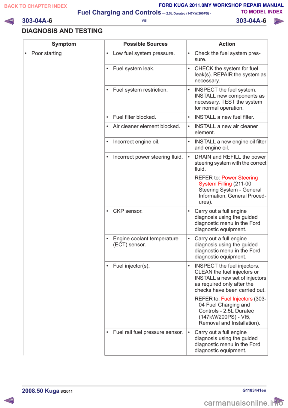
Action
Possible Sources
Symptom
• Check the fuel system pres-sure.
• Low fuel system pressure.
• Poor starting
• CHECK the system for fuelleak(s). REPAIR the system as
necessary.
• Fuel system leak.
• INSPECT the fuel system.INSTALL new components as
necessary. TEST the system
for normal operation.
• Fuel system restriction.
• INSTALL a new fuel filter.
• Fuel filter blocked.
• INSTALL a new air cleanerelement.
• Air cleaner element blocked.
• INSTALL a new engine oil filterand engine oil.
• Incorrect engine oil.
• DRAIN and REFILL the powersteering system with the correct
fluid.
REFER to: Power Steering
System Filling (211-00
Steering System - General
Information, General Proced-
ures).
• Incorrect power steering fluid.
• Carry out a full enginediagnosis using the guided
diagnostic menu in the Ford
diagnostic equipment.
• CKP sensor.
• Carry out a full enginediagnosis using the guided
diagnostic menu in the Ford
diagnostic equipment.
• Engine coolant temperature
(ECT) sensor.
• INSPECT the fuel injectors.CLEAN the fuel injectors or
INSTALL a new set of injectors
as required only after the
checks have been carried out.
REFER to: Fuel Injectors (303-
04 Fuel Charging and
Controls - 2.5L Duratec
(147kW/200PS) - VI5,
Removal and Installation).
• Fuel injector(s).
• Carry out a full enginediagnosis using the guided
diagnostic menu in the Ford
diagnostic equipment.
• Fuel rail fuel pressure sensor.
G1183441en2008.50 Kuga8/2011
303-04A-
6
Fuel Charging and Controls
— 2.5L Duratec (147kW/200PS) -
VI5
303-04A- 6
DIAGNOSIS AND TESTING
TO MODEL INDEX
BACK TO CHAPTER INDEX
FORD KUGA 2011.0MY WORKSHOP REPAIR MANUAL
Page 1704 of 2057
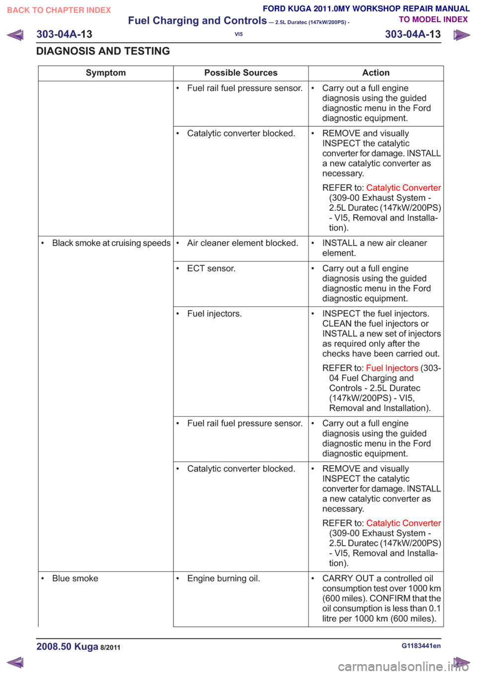
Action
Possible Sources
Symptom
• Carry out a full enginediagnosis using the guided
diagnostic menu in the Ford
diagnostic equipment.
• Fuel rail fuel pressure sensor.
• REMOVE and visuallyINSPECT the catalytic
converter for damage. INSTALL
a new catalytic converter as
necessary.
REFER to: Catalytic Converter
(309-00 Exhaust System -
2.5L Duratec (147kW/200PS)
- VI5, Removal and Installa-
tion).
• Catalytic converter blocked.
• INSTALL a new air cleanerelement.
• Air cleaner element blocked.
• Black smoke at cruising speeds
• Carry out a full enginediagnosis using the guided
diagnostic menu in the Ford
diagnostic equipment.
• ECT sensor.
• INSPECT the fuel injectors.CLEAN the fuel injectors or
INSTALL a new set of injectors
as required only after the
checks have been carried out.
REFER to: Fuel Injectors (303-
04 Fuel Charging and
Controls - 2.5L Duratec
(147kW/200PS) - VI5,
Removal and Installation).
• Fuel injectors.
• Carry out a full enginediagnosis using the guided
diagnostic menu in the Ford
diagnostic equipment.
• Fuel rail fuel pressure sensor.
• REMOVE and visuallyINSPECT the catalytic
converter for damage. INSTALL
a new catalytic converter as
necessary.
REFER to: Catalytic Converter
(309-00 Exhaust System -
2.5L Duratec (147kW/200PS)
- VI5, Removal and Installa-
tion).
• Catalytic converter blocked.
• CARRY OUT a controlled oilconsumption test over 1000 km
(600 miles). CONFIRM that the
oil consumption is less than 0.1
litre per 1000 km (600 miles).
• Engine burning oil.
• Blue smoke
G1183441en2008.50 Kuga8/2011
303-04A- 13
Fuel Charging and Controls
— 2.5L Duratec (147kW/200PS) -
VI5
303-04A- 13
DIAGNOSIS AND TESTING
TO MODEL INDEX
BACK TO CHAPTER INDEX
FORD KUGA 2011.0MY WORKSHOP REPAIR MANUAL
Page 1708 of 2057
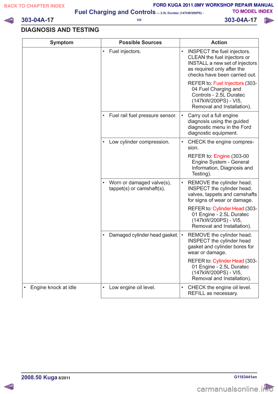
Action
Possible Sources
Symptom
• INSPECT the fuel injectors.CLEAN the fuel injectors or
INSTALL a new set of injectors
as required only after the
checks have been carried out.
REFER to: Fuel Injectors (303-
04 Fuel Charging and
Controls - 2.5L Duratec
(147kW/200PS) - VI5,
Removal and Installation).
• Fuel injectors.
• Carry out a full enginediagnosis using the guided
diagnostic menu in the Ford
diagnostic equipment.
• Fuel rail fuel pressure sensor.
• CHECK the engine compres-sion.
REFER to: Engine(303-00
Engine System - General
Information, Diagnosis and
Testing).
• Low cylinder compression.
• REMOVE the cylinder head.INSPECT the cylinder head,
valves, tappets and camshafts
for signs of wear or damage.
REFER to: Cylinder Head (303-
01 Engine - 2.5L Duratec
(147kW/200PS) - VI5,
Removal and Installation).
• Worn or damaged valve(s),
tappet(s) or camshaft(s).
• REMOVE the cylinder head.INSPECT the cylinder head
gasket and cylinder bores for
wear or damage.
REFER to: Cylinder Head (303-
01 Engine - 2.5L Duratec
(147kW/200PS) - VI5,
Removal and Installation).
• Damaged cylinder head gasket.
• CHECK the engine oil level.REFILL as necessary.
• Low engine oil level.
• Engine knock at idle
G1183441en2008.50 Kuga8/2011
303-04A- 17
Fuel Charging and Controls
— 2.5L Duratec (147kW/200PS) -
VI5
303-04A- 17
DIAGNOSIS AND TESTING
TO MODEL INDEX
BACK TO CHAPTER INDEX
FORD KUGA 2011.0MY WORKSHOP REPAIR MANUAL
Page 1715 of 2057
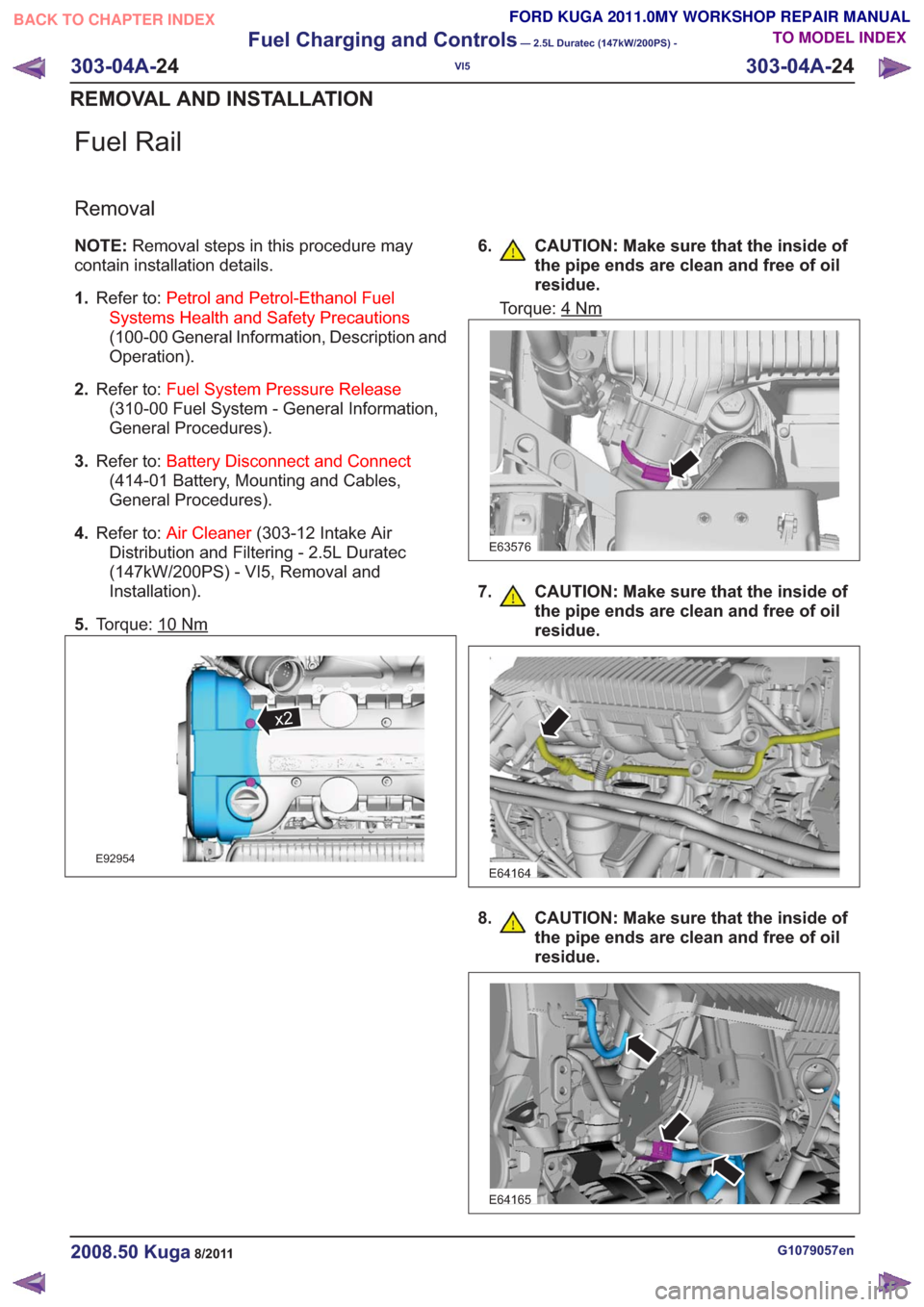
Fuel Rail
Removal
NOTE:Removal steps in this procedure may
contain installation details.
1. Refer to: Petrol and Petrol-Ethanol Fuel
Systems Health and Safety Precautions
(100-00 General Information, Description and
Operation).
2. Refer to: Fuel System Pressure Release
(310-00 Fuel System - General Information,
General Procedures).
3. Refer to: Battery Disconnect and Connect
(414-01 Battery, Mounting and Cables,
General Procedures).
4. Refer to: Air Cleaner (303-12 Intake Air
Distribution and Filtering - 2.5L Duratec
(147kW/200PS) - VI5, Removal and
Installation).
5. Torque: 10
Nm
x2x2
E92954
6. CAUTION: Make sure that the inside of
the pipe ends are clean and free of oil
residue.
Torque: 4Nm
E63576
7. CAUTION: Make sure that the inside ofthe pipe ends are clean and free of oil
residue.
E64164
8. CAUTION: Make sure that the inside ofthe pipe ends are clean and free of oil
residue.
E64165
G1079057en2008.50 Kuga8/2011
303-04A- 24
Fuel Charging and Controls
— 2.5L Duratec (147kW/200PS) -
VI5
303-04A- 24
REMOVAL AND INSTALLATION
TO MODEL INDEX
BACK TO CHAPTER INDEX
FORD KUGA 2011.0MY WORKSHOP REPAIR MANUAL
Page 1719 of 2057
6
79108
123
4
5
6
79108
E97592
Description
Item
Exhaust manifold
1
PCV (positive crankcase ventilation)- hose
Comments:to cylinder head
2
Vacuum line - recirculated air valve
Comments:to intake manifold
3
Coolant return pipe
4Description
Item
Turbo boost pressure controller
5
Oil supply pipe - TC
6
Wastegate control valve
7
TC
Comments:Contains the recirculated air valve
8
Coolant supply pipe
9
Oil return pipe - TC
10
G1032424en2008.50 Kuga8/2011
303-04B- 3
Fuel Charging and Controls - Turbocharger
—
2.5L Duratec (147kW/200PS) - VI5
303-04B- 3
DESCRIPTION AND OPERATION
TO MODEL INDEX
BACK TO CHAPTER INDEX
FORD KUGA 2011.0MY WORKSHOP REPAIR MANUAL