2011 FORD KUGA oil pressure
[x] Cancel search: oil pressurePage 129 of 2057

High-Pressure Cutoff Switch
Materials
Specification
Name
WSH-M1C231-B /
6U7J-M1C231-AA
Compressor Oil - Air
Conditioning
Removal
NOTE: Removal steps in this procedure may
contain installation details.
1. Refer to: Air Conditioning (A/C) System Health
and Safety Precautions (100-00 General
Information, Description and Operation).
2. Torque: 8 Nm
Installation
1.
To install, reverse the removal procedure.
2. Coat the o-ring seals.
Material: Compressor Oil - Air Conditioning
(WSH-M1C231-B / 6U7J-M1C231-AA)
refrigerant oil G1065545en
2008.50 Kuga 8/2011 412-01-59
Climate Control
412-01-59
REMOVAL AND INSTALLATIONTO MODEL INDEX
BACK TO CHAPTER INDEX
FORD KUGA 2011.0MY WORKSHOP REPAIR MANUALE100944
Page 187 of 2057

Description
Item
Instrument Cluster
1
PCM (powertrain control module)
2
EHPS (electro-hydraulic power steering)
control module
3
Audio unit
4
GEM (generic electronic module)
5
RCM (restraints control module)
6
PATS transceiver
7 Description
Item
Steering wheel lock module
8
Left-hand steering column switch
9
Fuel level sensor
10
Washer water level warning lamp switch
11
Accelerator pedal position sensor
12
CPP (clutch pedal position) sensor/BPP
(brake pedal position) sensor
13
Lighting control switch
14
System Operation
Instrument Cluster
The instrument cluster contains analog displays
as well as warning and control lamps for displaying
the system status; in addiiton, there is an LCD
indicator field for driver information.
The instrument cluster receives the following
signals from the PCM via the high speed CAN
(controller area network) Bus (HS-CAN):
• Vehicle speed – The PCM receives the necessary signalsfrom the ABS (anti-lock brake system) wheel
sensors from the ABS control unit on the
HS-CAN.
• Engine Coolant Temperature
• Engine oil pressure.
• Engine speed
The instrument cluster receives the following
signals from the GEM via the medium speed CAN
Bus (MS-CAN):
• Ambient temperature
• Brake fluid level
• Handbrake control
• Door latch control
• Liftgate latch control
• High beam control
• Headlamp flasher control
• Direction indicator control
The fuel level signal is sent by the two fuel level
sensors in the fuel pumps in the semitrailer tank,
which is wired to the instrument cluster. The
sensors are connected in series, and the total
resistance is determined from the two individual resistors. The instrument cluster converts the raw
fuel level signal into a damped fuel level value.
The odometer shows the total distance travelled
by the vehicle and is based on the same signal as
is processed for the daily mileage counter. The
value is recorded by the instrument cluster and
stored in a protected EEPROM (Electronically
Erasable Programmable Read Only Memory) area.
This area is a memory protected against
manipulation. If the instrument cluster detects an
error in this memory area, e.g. through damage,
the driver is notified with the "Odometer error"
message.
Message center
The message center is operated using the left-hand
switch on the steering column.
The SET/RESET button is activated to select a
submenu and change the settings. If signal tones
have been activated, a short acoustic signal will
sound each time a button is pressed.
By turning the rotary switch, the different menu
displays can be scrolled through or a setting
selected.
In this display, the navigation system can also
display direction and distance information.
In addition, safety and warning messages can be
displayed in this system, such as "Coolant
overheating", "Engine system error" or "Washer
fluid level too low". In addition to a safety message,
a general warning light (red/yellow) lights up.
G1030770en
2008.50 Kuga 8/2011 413-01-4
Instrument Cluster
413-01-4
DESCRIPTION AND OPERATIONTO MODEL INDEX
BACK TO CHAPTER INDEX
FORD KUGA 2011.0MY WORKSHOP REPAIR MANUAL
Page 190 of 2057

Instrument Cluster
Refer to
Wiring Diagrams Section 413-01, for
schematic and connector information. General Equipment
The Ford approved diagnostic tool
Inspection and Verification
1. Verify the customer concern.
2. Visually inspect for obvious signs of mechanical
or electrical damage.
Visual Inspection Chart Electrical
Mechanical
– Fuse(s)
– Wiring harness
– Electricalconnector(s)
– Instrument cluster
– Light emitting diode(s) (LED)(s)
– Engine oil filter
– Engine oil level
–
Engine coolant level
– Oil pressure switch
– Engine coolant level
– Coolant thermostat
– Engine coolant temperature (ECT)
sensor
– Fuel gauge
– Collapsed or damaged fuel tank
– Recirculation hose
– Fuel tank filler pipe/hose
– Indicated fuel level
– Fuel lines
– Fuel tank filler cap
– Fuel filter (external to the fuel tank)
– Fuel tank
– Door adjustment
3. If an obvious cause for an observed or reported concern is found, correct the cause (if possible)
before proceeding to the next step.
4. NOTE: If none of the following warning indicators are operating correctly this may
indicate a concern with the central junction
box (CJB). If only one or two of the following
warning indicators are not operating
correctly this may indicate an instrument
cluster concern. Verify the following warning indicators are
working correctly:
• Charging.
• Turn signals.
• Headlamps.
5. If the cause is not visually evident, verify the symptom and refer to the diagnostic tab within
the Ford approved diagnostic tool.
Configuration of the Instrument Cluster
The instrument cluster is a programmable module,
which must be configured by selecting the
Programmable Module Installation Routine on the
Ford approved diagnostic tool.
NOTE: When the new instrument cluster has been
configured with the odometer value, its
configuration cannot be decreased or matched. A
new configuration will result in an increase in the
displayed odometer value by a minimum of two
units.
NOTE: The odometer value must be recorded from
the original instrument cluster before removal.
If the odometer value cannot be obtained from
the original instrument cluster (display failure)
the customer should supply the approximate
value.
The following features will need to be configured
when a new instrument cluster is installed:
• Anti-lock Brake System (ABS)
• All wheel drive
• Keyless vehicle entry
• Electronic power assisted steering
• Trip computer
• Voice control
• Parking aid
• Belt minder
• Safety belt not fastened
• Right hand drive
• Overspeed warning
• Reverse warning
• Turbocharger boost pressure
• Speed control
• Auxiliary heater
• Suspension control
• Washer fluid sensor G1054964en
2008.50 Kuga 8/2011 413-01-7
Instrument Cluster
413-01-7
DIAGNOSIS AND TESTINGTO MODEL INDEX
BACK TO CHAPTER INDEX
FORD KUGA 2011.0MY WORKSHOP REPAIR MANUAL
Page 1517 of 2057
SECTION 303-00 Engine System - General Information
VEHICLE APPLICATION:2008.50 Kuga
PA G E
CONTENTS
DIAGNOSIS AND TESTING
303-00-2
Engine ........................................................................\
.........................................................
303-00-9
Engine - Oil Leaks ........................................................................\
......................................
303-00-9
Ultraviolet (UV) Testing ........................................................................\
...............................
303-00-9
Measure the compression pressure ........................................................................\
...........
303-00-10
Measure the compression pressure (Engine - 2.5L Duratec-ST (VI5)) ..............................
303-00-11
Measure the compression pressure (Engine - 2.0L Duratorq-TDCi (DW) Diesel) .............
303-00-14
Measure the oil pressure (21 113 0) ........................................................................\
...........
303-00-14
Measure the oil pressure (Engine - 2.5L Duratec-ST (VI5)) ...............................................
303-00-16
Measure the oil pressure (Engine - 2.0L Duratorq-TDCi (DW) Diesel) ..............................
303-00-17
Valve train analysis - static (engine off) ........................................................................\
......
303-00-1
Engine System - General Information
303-00- 1
.
TO MODEL INDEX
BACK TO CHAPTER INDEX
FORD KUGA 2011.0MY WORKSHOP REPAIR MANUAL
Page 1519 of 2057
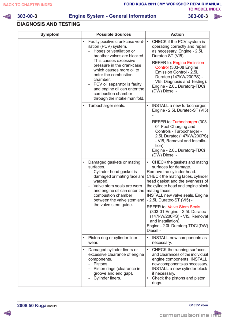
Action
Possible Sources
Symptom
• CHECK if the PCV system isoperating correctly and repair
as necessary. Engine - 2.5L
Duratec-ST (VI5) -
REFER to: Engine Emission
Control (303-08 Engine
Emission Control - 2.5L
Duratec (147kW/200PS) -
VI5, Diagnosis and Testing).
Engine - 2.0L Duratorq-TDCi
(DW) Diesel -
• Faulty positive crankcase vent-
ilation (PCV) system.
- Hoses or ventilation orbreather valves are blocked.
This causes excessive
pressure in the crankcase
which causes more oil to
enter the combustion
chamber.
- PCV oil separator is faulty and engine oil can enter the
combustion chamber
through the intake manifold.
• INSTALL a new turbocharger.Engine - 2.5L Duratec-ST (VI5)
-
REFER to: Turbocharger (303-
04 Fuel Charging and
Controls - Turbocharger -
2.5L Duratec (147kW/200PS)
- VI5, Removal and Installa-
tion).
Engine - 2.0L Duratorq-TDCi
(DW) Diesel -
• Turbocharger seals.
• CHECK the gaskets and matingsurfaces for damage.
Remove the cylinder head.
CHECK the mating faces, cylinder
head gasket and the evenness of
the cylinder head and engine block
mating faces.
INSTALL new valve seals. Engine
- 2.5L Duratec-ST (VI5) -
REFER to: Valve Stem Seals
(303-01 Engine - 2.5L Duratec
(147kW/200PS) - VI5, Removal
and Installation).
Engine - 2.0L Duratorq-TDCi (DW)
Diesel -
• Damaged gaskets or mating
surfaces.
- Cylinder head gasket isdamaged or mating face are
warped.
- Valve stem seals are worn and engine oil can enter the
combustion chamber
between the valve stem and
the valve stem guide.
• INSTALL new components asnecessary.
• Piston ring or cylinder liner
wear.
• CHECK the running surfacesand clearances of the individual
engine components. INSTALL
new components as necessary.
INSTALL a new cylinder block
if necessary.
• Check the pistons and piston rings.
• Damaged cylinder liners or
excessive clearance of engine
components.
- Pistons.
- Piston rings (clearance ingroove and end gap).
- Cylinder liners.
G1055128en2008.50 Kuga8/2011
303-00- 3
Engine System - General Information
303-00- 3
DIAGNOSIS AND TESTING
TO MODEL INDEX
BACK TO CHAPTER INDEX
FORD KUGA 2011.0MY WORKSHOP REPAIR MANUAL
Page 1525 of 2057
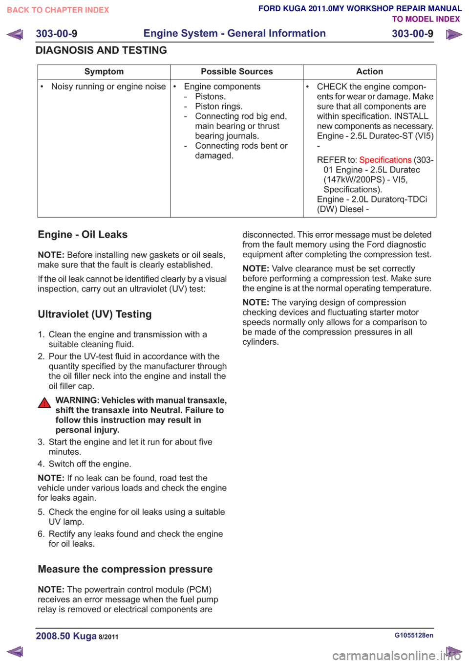
Action
Possible Sources
Symptom
• CHECK the engine compon-ents for wear or damage. Make
sure that all components are
within specification. INSTALL
new components as necessary.
Engine - 2.5L Duratec-ST (VI5)
-
REFER to: Specifications (303-
01 Engine - 2.5L Duratec
(147kW/200PS) - VI5,
Specifications).
Engine - 2.0L Duratorq-TDCi
(DW) Diesel -
• Engine components
- Pistons.
- Piston rings.
- Connecting rod big end,main bearing or thrust
bearing journals.
- Connecting rods bent or damaged.
• Noisy running or engine noise
Engine - Oil Leaks
NOTE:
Before installing new gaskets or oil seals,
make sure that the fault is clearly established.
If the oil leak cannot be identified clearly by a visual
inspection, carry out an ultraviolet (UV) test:
Ultraviolet (UV) Testing
1. Clean the engine and transmission with a suitable cleaning fluid.
2. Pour the UV-test fluid in accordance with the quantity specified by the manufacturer through
the oil filler neck into the engine and install the
oil filler cap.
WARNING: Vehicles with manual transaxle,
shift the transaxle into Neutral. Failure to
follow this instruction may result in
personal injury.
3. Start the engine and let it run for about five minutes.
4. Switch off the engine.
NOTE: If no leak can be found, road test the
vehicle under various loads and check the engine
for leaks again.
5. Check the engine for oil leaks using a suitable UV lamp.
6. Rectify any leaks found and check the engine for oil leaks.
Measure the compression pressure
NOTE: The powertrain control module (PCM)
receives an error message when the fuel pump
relay is removed or electrical components are disconnected. This error message must be deleted
from the fault memory using the Ford diagnostic
equipment after completing the compression test.
NOTE:
Valve clearance must be set correctly
before performing a compression test. Make sure
the engine is at the normal operating temperature.
NOTE: The varying design of compression
checking devices and fluctuating starter motor
speeds normally only allows for a comparison to
be made of the compression pressures in all
cylinders.
G1055128en2008.50 Kuga8/2011
303-00- 9
Engine System - General Information
303-00- 9
DIAGNOSIS AND TESTING
TO MODEL INDEX
BACK TO CHAPTER INDEX
FORD KUGA 2011.0MY WORKSHOP REPAIR MANUAL
Page 1526 of 2057
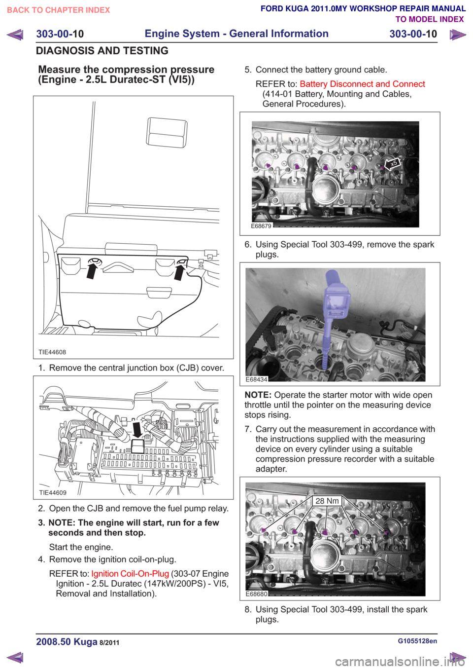
Measure the compression pressure
(Engine - 2.5L Duratec-ST (VI5))
TIE44608
1. Remove the central junction box (CJB) cover.
TIE44609
2. Open the CJB and remove the fuel pump relay.
3. NOTE: The engine will start, run for a fewseconds and then stop.
Start the engine.
4. Remove the ignition coil-on-plug.
REFER to: Ignition Coil-On-Plug (303-07 Engine
Ignition - 2.5L Duratec (147kW/200PS) - VI5,
Removal and Installation). 5. Connect the battery ground cable.
REFER to: Battery Disconnect and Connect
(414-01 Battery, Mounting and Cables,
General Procedures).
E68679
x5
6. Using Special Tool 303-499, remove the spark plugs.
E68434
NOTE: Operate the starter motor with wide open
throttle until the pointer on the measuring device
stops rising.
7. Carry out the measurement in accordance with the instructions supplied with the measuring
device on every cylinder using a suitable
compression pressure recorder with a suitable
adapter.
E68680
28 Nm
8. Using Special Tool 303-499, install the sparkplugs.
G1055128en2008.50 Kuga8/2011
303-00- 10
Engine System - General Information
303-00- 10
DIAGNOSIS AND TESTING
TO MODEL INDEX
BACK TO CHAPTER INDEX
FORD KUGA 2011.0MY WORKSHOP REPAIR MANUAL
Page 1527 of 2057
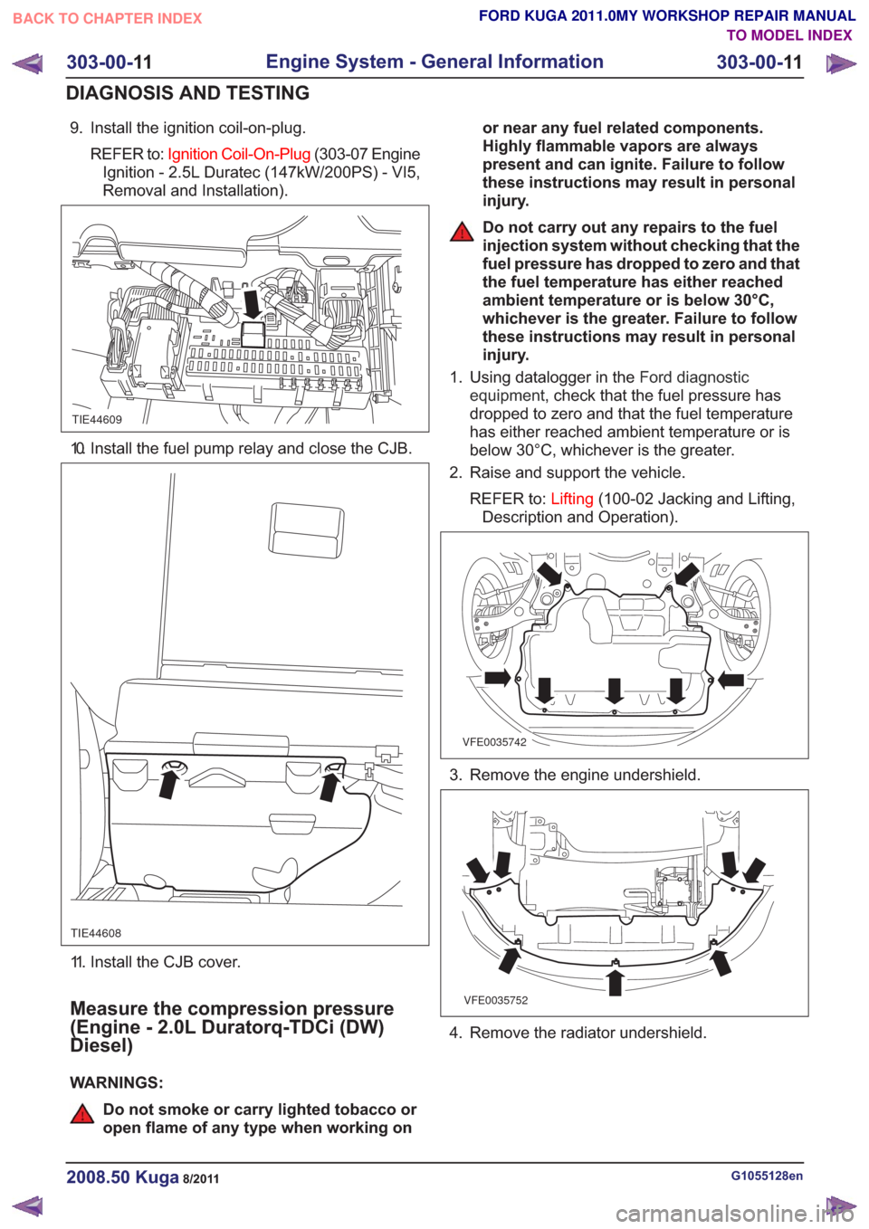
9. Install the ignition coil-on-plug.REFER to: Ignition Coil-On-Plug (303-07 Engine
Ignition - 2.5L Duratec (147kW/200PS) - VI5,
Removal and Installation).
TIE44609
10. Install the fuel pump relay and close the CJB.
TIE44608
11. Install the CJB cover.
Measure the compression pressure
(Engine - 2.0L Duratorq-TDCi (DW)
Diesel)
WARNINGS:
Do not smoke or carry lighted tobacco or
open flame of any type when working on or near any fuel related components.
Highly flammable vapors are always
present and can ignite. Failure to follow
these instructions may result in personal
injury.
Do not carry out any repairs to the fuel
injection system without checking that the
fuel pressure has dropped to zero and that
the fuel temperature has either reached
ambient temperature or is below 30°C,
whichever is the greater. Failure to follow
these instructions may result in personal
injury.
1. Using datalogger in the Ford diagnostic
equipment , check that the fuel pressure has
dropped to zero and that the fuel temperature
has either reached ambient temperature or is
below 30°C, whichever is the greater.
2. Raise and support the vehicle.
REFER to: Lifting(100-02 Jacking and Lifting,
Description and Operation).
VFE0035742
3. Remove the engine undershield.
VFE0035752
4. Remove the radiator undershield.
G1055128en2008.50 Kuga8/2011
303-00- 11
Engine System - General Information
303-00- 11
DIAGNOSIS AND TESTING
TO MODEL INDEX
BACK TO CHAPTER INDEX
FORD KUGA 2011.0MY WORKSHOP REPAIR MANUAL