Page 1536 of 2057

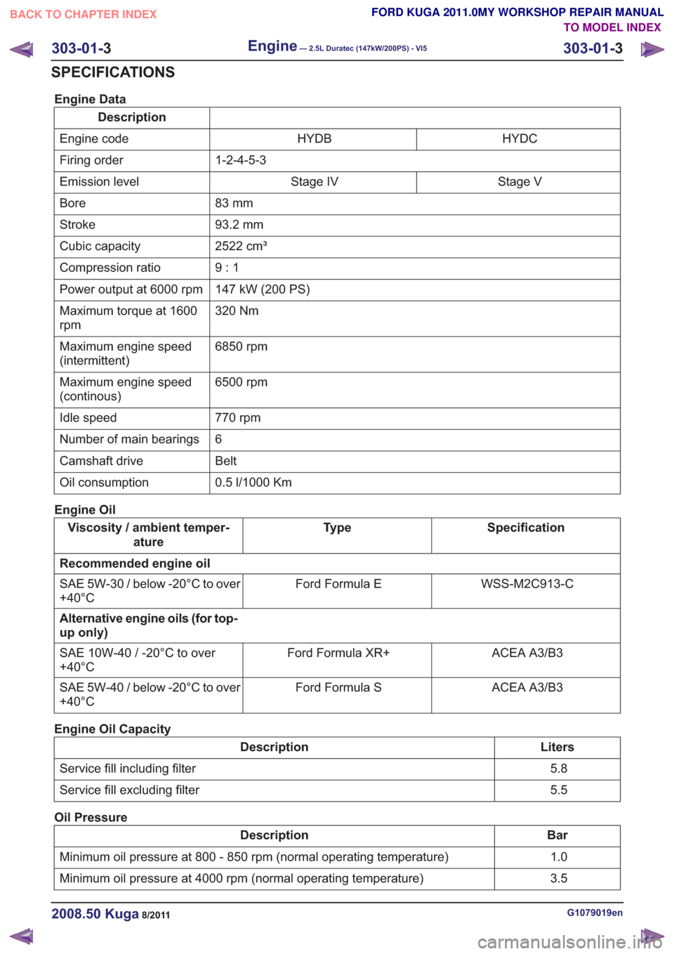
Engine Data
DescriptionHYDC
HYDB
Engine code
1-2-4-5-3
Firing order
Stage V
Stage IV
Emission level
83 mm
Bore
93.2 mm
Stroke
2522 cm³
Cubic capacity
9:1
Compression ratio
147 kW (200 PS)
Power output at 6000 rpm
320 Nm
Maximum torque at 1600
rpm
6850 rpm
Maximum engine speed
(intermittent)
6500 rpm
Maximum engine speed
(continous)
770 rpm
Idle speed
6
Number of main bearings
Belt
Camshaft drive
0.5 l/1000 Km
Oil consumption
Engine Oil
Specification
Ty p e
Viscosity / ambient temper-
ature
Recommended engine oil WSS-M2C913-C
Ford Formula E
SAE 5W-30 / below -20°C to over
+40°C
Alternative engine oils (for top-
up only)
ACEA A3/B3
Ford Formula XR+
SAE 10W-40 / -20°C to over
+40°C
ACEA A3/B3
Ford Formula S
SAE 5W-40 / below -20°C to over
+40°C
Engine Oil Capacity
Liters
Description
5.8
Service fill including filter
5.5
Service fill excluding filter
Oil Pressure
Bar
Description
1.0
Minimum oil pressure at 800 - 850 rpm (normal operating temperature)
3.5
Minimum oil pressure at 4000 rpm (normal operating temperature)
G1079019en2008.50 Kuga8/2011
303-01- 3
Engine— 2.5L Duratec (147kW/200PS) - VI5303-01-
3
SPECIFICATIONS
TO MODEL INDEX
BACK TO CHAPTER INDEX
FORD KUGA 2011.0MY WORKSHOP REPAIR MANUAL
Page 1537 of 2057

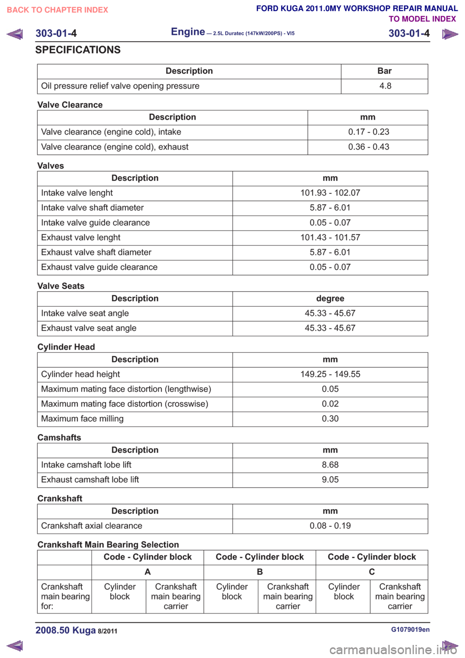
Bar
Description
4.8
Oil pressure relief valve opening pressure
Valve Clearance
mm
Description
0.17 - 0.23
Valve clearance (engine cold), intake
0.36 - 0.43
Valve clearance (engine cold), exhaust
Valves
mm
Description
101.93 - 102.07
Intake valve lenght
5.87 - 6.01
Intake valve shaft diameter
0.05 - 0.07
Intake valve guide clearance
101.43 - 101.57
Exhaust valve lenght
5.87 - 6.01
Exhaust valve shaft diameter
0.05 - 0.07
Exhaust valve guide clearance
Valve Seats
degree
Description
45.33 - 45.67
Intake valve seat angle
45.33 - 45.67
Exhaust valve seat angle
Cylinder Head
mm
Description
149.25 - 149.55
Cylinder head height
0.05
Maximum mating face distortion (lengthwise)
0.02
Maximum mating face distortion (crosswise)
0.30
Maximum face milling
Camshafts
mm
Description
8.68
Intake camshaft lobe lift
9.05
Exhaust camshaft lobe lift
Crankshaft
mm
Description
0.08 - 0.19
Crankshaft axial clearance
Crankshaft Main Bearing Selection
Code - Cylinder block
Code - Cylinder block
Code - Cylinder block
C
B
A
Crankshaft
main bearing carrier
Cylinder
block
Crankshaft
main bearing carrier
Cylinder
block
Crankshaft
main bearing carrier
Cylinder
block
Crankshaft
main bearing
for:
G1079019en2008.50 Kuga8/2011
303-01-
4
Engine— 2.5L Duratec (147kW/200PS) - VI5303-01-
4
SPECIFICATIONS
TO MODEL INDEX
BACK TO CHAPTER INDEX
FORD KUGA 2011.0MY WORKSHOP REPAIR MANUAL
Page 1539 of 2057
Engine – Component Location
Engine
E62441
1
65
4
3
2
9
10
13
12
11
8
7
Description
Item
Front engine cover
1
Rear engine cover
2
CMP (camshaft position) Sensor - intake
camshaft
3
CMP Sensor - exhaust camshaft
4Description
Item
Intake variable camshaft timing oil control
solenoid
5
Exhaust variable camshaft timing oil
control solenoid
6
Exhaust VCT control unit
7
Intake VCT control unit
8
G1032415en2008.50 Kuga8/2011
303-01- 6
Engine— 2.5L Duratec (147kW/200PS) - VI5303-01-
6
DESCRIPTION AND OPERATION
TO MODEL INDEX
BACK TO CHAPTER INDEX
FORD KUGA 2011.0MY WORKSHOP REPAIR MANUAL
Page 1541 of 2057
Description
Item
Cylinder block
1
Bedplate
2Description
Item
3 Oil sump
G1032415en2008.50 Kuga8/2011
303-01- 8
Engine— 2.5L Duratec (147kW/200PS) - VI5303-01-
8
DESCRIPTION AND OPERATION
TO MODEL INDEX
BACK TO CHAPTER INDEX
FORD KUGA 2011.0MY WORKSHOP REPAIR MANUAL
Page 1546 of 2057

Description
Item
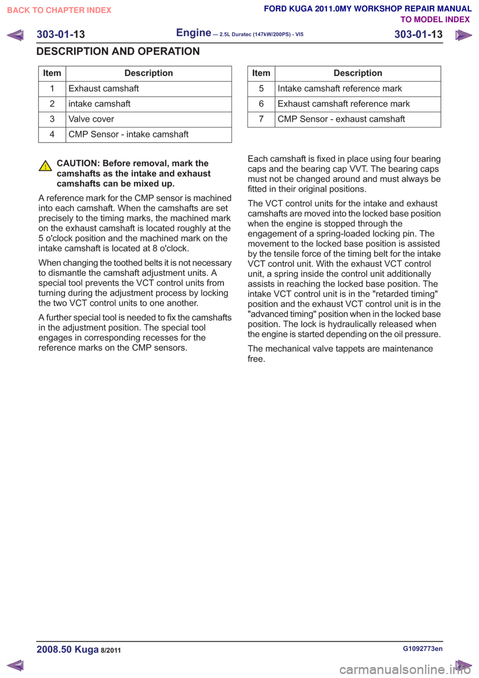
Exhaust camshaft
1
intake camshaft
2
Valve cover
3
CMP Sensor - intake camshaft
4Description
Item
Intake camshaft reference mark
5
Exhaust camshaft reference mark
6
CMP Sensor - exhaust camshaft
7
CAUTION: Before removal, mark the
camshafts as the intake and exhaust
camshafts can be mixed up.
A reference mark for the CMP sensor is machined
into each camshaft. When the camshafts are set
precisely to the timing marks, the machined mark
on the exhaust camshaft is located roughly at the
5 o'clock position and the machined mark on the
intake camshaft is located at 8 o'clock.
When changing the toothed belts it is not necessary
to dismantle the camshaft adjustment units. A
special tool prevents the VCT control units from
turning during the adjustment process by locking
the two VCT control units to one another.
A further special tool is needed to fix the camshafts
in the adjustment position. The special tool
engages in corresponding recesses for the
reference marks on the CMP sensors. Each camshaft is fixed in place using four bearing
caps and the bearing cap VVT. The bearing caps
must not be changed around and must always be
fitted in their original positions.
The VCT control units for the intake and exhaust
camshafts are moved into the locked base position
when the engine is stopped through the
engagement of a spring-loaded locking pin. The
movement to the locked base position is assisted
by the tensile force of the timing belt for the intake
VCT control unit. With the exhaust VCT control
unit, a spring inside the control unit additionally
assists in reaching the locked base position. The
intake VCT control unit is in the "retarded timing"
position and the exhaust VCT control unit is in the
"advanced timing" position when in the locked base
position. The lock is hydraulically released when
the engine is started depending on the oil pressure.
The mechanical valve tappets are maintenance
free.
G1092773en2008.50 Kuga8/2011
303-01-
13
Engine— 2.5L Duratec (147kW/200PS) - VI5303-01-
13
DESCRIPTION AND OPERATION
TO MODEL INDEX
BACK TO CHAPTER INDEX
FORD KUGA 2011.0MY WORKSHOP REPAIR MANUAL
Page 1547 of 2057

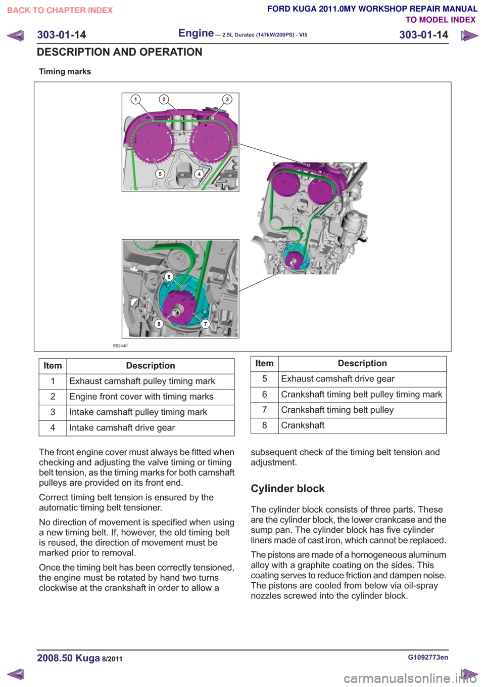
Timing marks
132
45
6
78
E62440
Description
Item
Exhaust camshaft pulley timing mark
1
Engine front cover with timing marks
2
Intake camshaft pulley timing mark
3
Intake camshaft drive gear
4Description
Item
Exhaust camshaft drive gear
5
Crankshaft timing belt pulley timing mark
6
Crankshaft timing belt pulley
7
Crankshaft
8
The front engine cover must always be fitted when
checking and adjusting the valve timing or timing
belt tension, as the timing marks for both camshaft
pulleys are provided on its front end.
Correct timing belt tension is ensured by the
automatic timing belt tensioner.
No direction of movement is specified when using
a new timing belt. If, however, the old timing belt
is reused, the direction of movement must be
marked prior to removal.
Once the timing belt has been correctly tensioned,
the engine must be rotated by hand two turns
clockwise at the crankshaft in order to allow a subsequent check of the timing belt tension and
adjustment.
Cylinder block
The cylinder block consists of three parts. These
are the cylinder block, the lower crankcase and the
sump pan. The cylinder block has five cylinder
liners made of cast iron, which cannot be replaced.
The pistons are made of a homogeneous aluminum
alloy with a graphite coating on the sides. This
coating serves to reduce friction and dampen noise.
The pistons are cooled from below via oil-spray
nozzles screwed into the cylinder block.
G1092773en2008.50 Kuga8/2011
303-01-
14
Engine— 2.5L Duratec (147kW/200PS) - VI5303-01-
14
DESCRIPTION AND OPERATION
TO MODEL INDEX
BACK TO CHAPTER INDEX
FORD KUGA 2011.0MY WORKSHOP REPAIR MANUAL
Page 1548 of 2057
Crankshaft
E62853
123
467
5
Description
Item
Crankshaft
1
Timing belt pulley
2
Dowel
3Description
Item
Timing belt pulley splines
4
Wide spline
5
Crankshaft outer splines
6
Crankshaft inner splines
7
Located on the drive side of the crankshaft are two
sets of splines. The inner splines drive the oil
pump. The outer splines engage in the timing belt
pulley. The timing belt pulley can only be fitted onto the outer splines in a particular position. For this
purpose, one spline on the timing belt pulley and
one on the crankshaft have been made wider. The
dowel fixes the vibration damper in place.
G1092773en2008.50 Kuga8/2011
303-01-
15
Engine— 2.5L Duratec (147kW/200PS) - VI5303-01-
15
DESCRIPTION AND OPERATION
TO MODEL INDEX
BACK TO CHAPTER INDEX
FORD KUGA 2011.0MY WORKSHOP REPAIR MANUAL
Page 1550 of 2057
Variable camshaft timing
Timing retard
E62711
Description
Item
Camshaft pulley
1
Locking pin
2
Valve rotor
3
Rotor vane
4
Plunger
5Description
Item
Return spring
6
Camshaft adjuster solenoid
7
Duct connected to chamber (a)
A
Duct connected to chamber (b)
B
Oil feed duct
C
Oil return duct
Drive
G1032416en2008.50 Kuga8/2011
303-01- 17
Engine— 2.5L Duratec (147kW/200PS) - VI5303-01-
17
DESCRIPTION AND OPERATION
TO MODEL INDEX
BACK TO CHAPTER INDEX
FORD KUGA 2011.0MY WORKSHOP REPAIR MANUAL