2011 FORD KUGA engine oil
[x] Cancel search: engine oilPage 190 of 2057

Instrument Cluster
Refer to
Wiring Diagrams Section 413-01, for
schematic and connector information. General Equipment
The Ford approved diagnostic tool
Inspection and Verification
1. Verify the customer concern.
2. Visually inspect for obvious signs of mechanical
or electrical damage.
Visual Inspection Chart Electrical
Mechanical
– Fuse(s)
– Wiring harness
– Electricalconnector(s)
– Instrument cluster
– Light emitting diode(s) (LED)(s)
– Engine oil filter
– Engine oil level
–
Engine coolant level
– Oil pressure switch
– Engine coolant level
– Coolant thermostat
– Engine coolant temperature (ECT)
sensor
– Fuel gauge
– Collapsed or damaged fuel tank
– Recirculation hose
– Fuel tank filler pipe/hose
– Indicated fuel level
– Fuel lines
– Fuel tank filler cap
– Fuel filter (external to the fuel tank)
– Fuel tank
– Door adjustment
3. If an obvious cause for an observed or reported concern is found, correct the cause (if possible)
before proceeding to the next step.
4. NOTE: If none of the following warning indicators are operating correctly this may
indicate a concern with the central junction
box (CJB). If only one or two of the following
warning indicators are not operating
correctly this may indicate an instrument
cluster concern. Verify the following warning indicators are
working correctly:
• Charging.
• Turn signals.
• Headlamps.
5. If the cause is not visually evident, verify the symptom and refer to the diagnostic tab within
the Ford approved diagnostic tool.
Configuration of the Instrument Cluster
The instrument cluster is a programmable module,
which must be configured by selecting the
Programmable Module Installation Routine on the
Ford approved diagnostic tool.
NOTE: When the new instrument cluster has been
configured with the odometer value, its
configuration cannot be decreased or matched. A
new configuration will result in an increase in the
displayed odometer value by a minimum of two
units.
NOTE: The odometer value must be recorded from
the original instrument cluster before removal.
If the odometer value cannot be obtained from
the original instrument cluster (display failure)
the customer should supply the approximate
value.
The following features will need to be configured
when a new instrument cluster is installed:
• Anti-lock Brake System (ABS)
• All wheel drive
• Keyless vehicle entry
• Electronic power assisted steering
• Trip computer
• Voice control
• Parking aid
• Belt minder
• Safety belt not fastened
• Right hand drive
• Overspeed warning
• Reverse warning
• Turbocharger boost pressure
• Speed control
• Auxiliary heater
• Suspension control
• Washer fluid sensor G1054964en
2008.50 Kuga 8/2011 413-01-7
Instrument Cluster
413-01-7
DIAGNOSIS AND TESTINGTO MODEL INDEX
BACK TO CHAPTER INDEX
FORD KUGA 2011.0MY WORKSHOP REPAIR MANUAL
Page 199 of 2057

Oil Change Indicator Reset
1.
Turn the ignition key to position II without
cranking the engine.
2. Simultaneously press and hold the accelerator
pedal and the brake pedal for approximately 15
seconds until the oil change reminder indicator
starts to flash or the "Service Oil Reset
Complete" message appears in the information
and message center (if equipped).
3. Release the pedals.
4. Check that the oil change reminder indicator
has turned off or that there is no "Service Oil"
message in the information and message center
(if equipped). If the oil change reminder indicator
is still illuminated or the "Service Oil" message
is still displayed, turn the ignition key to position
0 and repeat the procedure from Step 1. If it has
turned off or the "Service Oil" message has
disappeared, proceed to Step 5.
5. Turn the ignition key to position 0 and leave it
there for at least 2 minutes so that the
powertrain control module (PCM) fully powers
down and updates the non-volatile memory
(NVM) in the PCM.
6. Turn the ignition key to position II without
cranking the engine and check that the oil
change reminder indicator is not illuminated or
that there is no "Service Oil" message displayed.
7. Turn the ignition key to position 0. G898940en
2008.50 Kuga 8/2011 413-09-4
Warning Devices
413-09-4
GENERAL PROCEDURESTO MODEL INDEX
BACK TO CHAPTER INDEX
FORD KUGA 2011.0MY WORKSHOP REPAIR MANUAL
Page 1270 of 2057
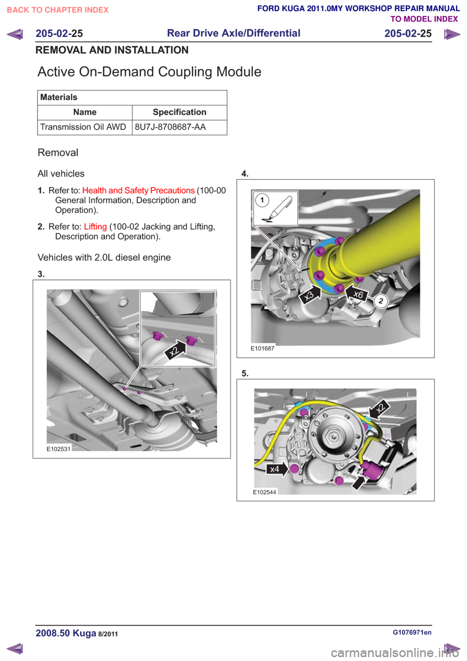
Active On-Demand Coupling Module
MaterialsSpecification
Name
8U7J-8708687-AA
Transmission Oil AWD
Removal
All vehicles
1. Refer to: Health and Safety Precautions (100-00
General Information, Description and
Operation).
2. Refer to: Lifting(100-02 Jacking and Lifting,
Description and Operation).
Vehicles with 2.0L diesel engine
3.
x2x2
E102531
4.
1
2x6x3
1
2x6x3
E101687
5.
x4
x2
x4
x2
E102544
G1076971en2008.50 Kuga8/2011
205-02- 25
Rear Drive Axle/Differential
205-02- 25
REMOVAL AND INSTALLATION
TO MODEL INDEX
BACK TO CHAPTER INDEX
FORD KUGA 2011.0MY WORKSHOP REPAIR MANUAL
Page 1273 of 2057
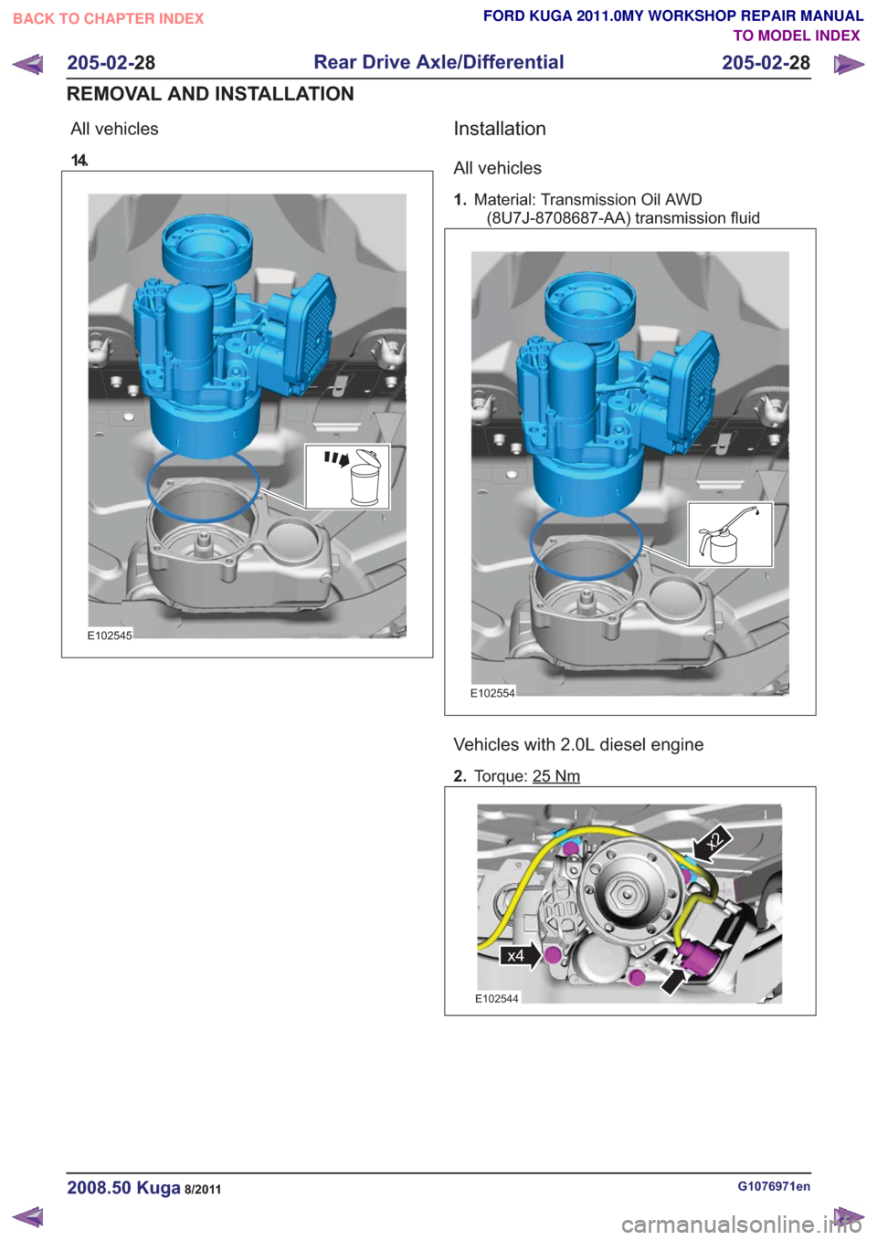
All vehicles
14.
E102545
Installation
All vehicles
1.Material: Transmission Oil AWD
(8U7J-8708687-AA) transmission fluid
E102554
Vehicles with 2.0L diesel engine
2. Torque: 25Nm
x4
x2
x4
x2
E102544
G1076971en2008.50 Kuga8/2011
205-02- 28
Rear Drive Axle/Differential
205-02- 28
REMOVAL AND INSTALLATION
TO MODEL INDEX
BACK TO CHAPTER INDEX
FORD KUGA 2011.0MY WORKSHOP REPAIR MANUAL
Page 1517 of 2057
SECTION 303-00 Engine System - General Information
VEHICLE APPLICATION:2008.50 Kuga
PA G E
CONTENTS
DIAGNOSIS AND TESTING
303-00-2
Engine ........................................................................\
.........................................................
303-00-9
Engine - Oil Leaks ........................................................................\
......................................
303-00-9
Ultraviolet (UV) Testing ........................................................................\
...............................
303-00-9
Measure the compression pressure ........................................................................\
...........
303-00-10
Measure the compression pressure (Engine - 2.5L Duratec-ST (VI5)) ..............................
303-00-11
Measure the compression pressure (Engine - 2.0L Duratorq-TDCi (DW) Diesel) .............
303-00-14
Measure the oil pressure (21 113 0) ........................................................................\
...........
303-00-14
Measure the oil pressure (Engine - 2.5L Duratec-ST (VI5)) ...............................................
303-00-16
Measure the oil pressure (Engine - 2.0L Duratorq-TDCi (DW) Diesel) ..............................
303-00-17
Valve train analysis - static (engine off) ........................................................................\
......
303-00-1
Engine System - General Information
303-00- 1
.
TO MODEL INDEX
BACK TO CHAPTER INDEX
FORD KUGA 2011.0MY WORKSHOP REPAIR MANUAL
Page 1518 of 2057
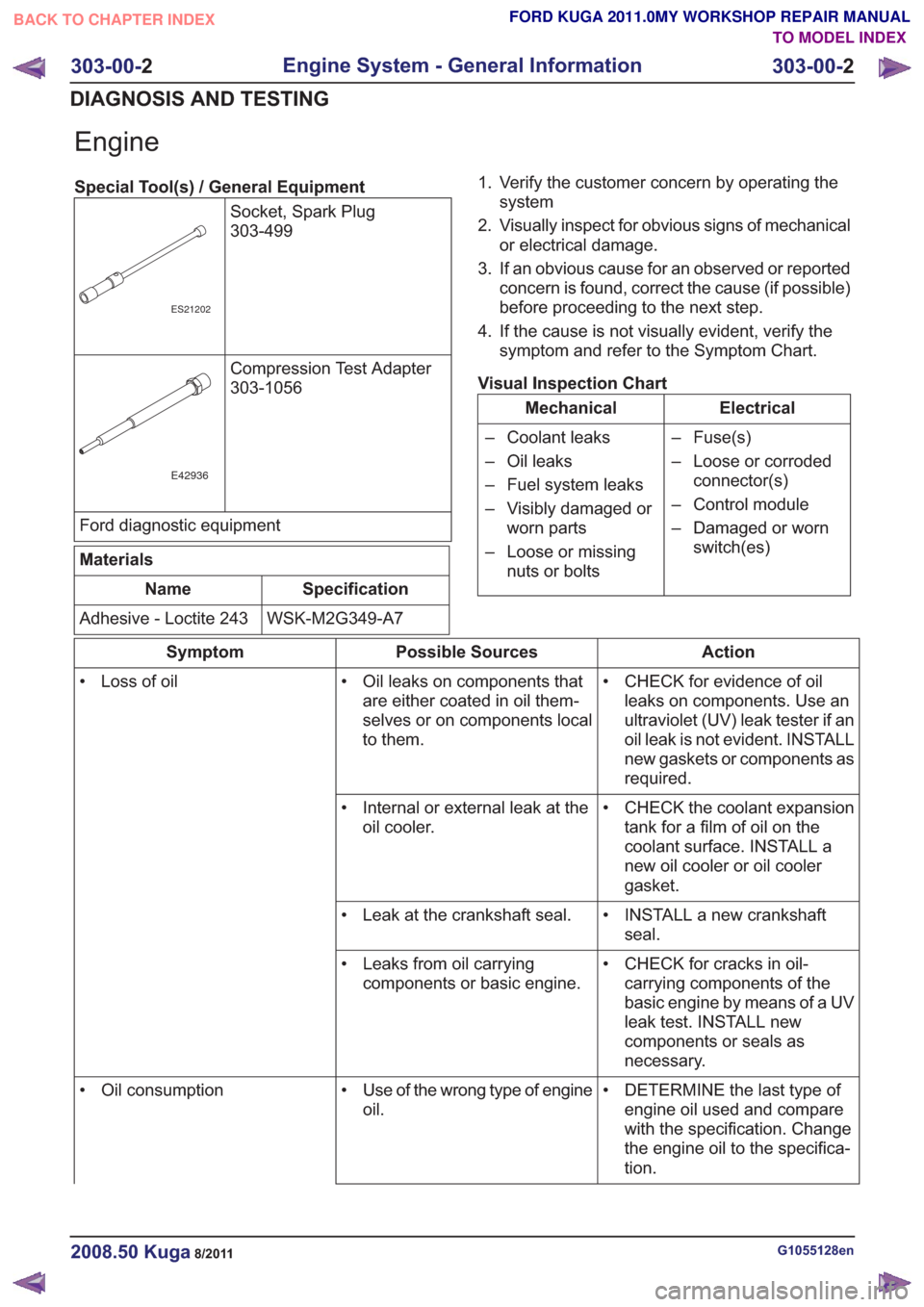
Engine
Special Tool(s) / General EquipmentSocket, Spark Plug
303-499
ES21202
Compression Test Adapter
303-1056
E42936
Ford diagnostic equipment
Materials
Specification
Name
WSK-M2G349-A7
Adhesive - Loctite 243 1. Verify the customer concern by operating the
system
2. Visually inspect for obvious signs of mechanical or electrical damage.
3. If an obvious cause for an observed or reported concern is found, correct the cause (if possible)
before proceeding to the next step.
4. If the cause is not visually evident, verify the symptom and refer to the Symptom Chart.
Visual Inspection Chart
Electrical
Mechanical
– Fuse(s)
– Loose or corrodedconnector(s)
– Control module
– Damaged or worn switch(es)
– Coolant leaks
– Oil leaks
– Fuel system leaks
– Visibly damaged or
worn parts
– Loose or missing nuts or bolts
Action
Possible Sources
Symptom
• CHECK for evidence of oilleaks on components. Use an
ultraviolet (UV) leak tester if an
oil leak is not evident. INSTALL
new gaskets or components as
required.
• Oil leaks on components that
are either coated in oil them-
selves or on components local
to them.
• Loss of oil
• CHECK the coolant expansiontank for a film of oil on the
coolant surface. INSTALL a
new oil cooler or oil cooler
gasket.
• Internal or external leak at the
oil cooler.
• INSTALL a new crankshaftseal.
• Leak at the crankshaft seal.
• CHECK for cracks in oil-carrying components of the
basic engine by means of a UV
leak test. INSTALL new
components or seals as
necessary.
• Leaks from oil carrying
components or basic engine.
• DETERMINE the last type ofengine oil used and compare
with the specification. Change
the engine oil to the specifica-
tion.
• Use of the wrong type of engine
oil.
• Oil consumption
G1055128en2008.50 Kuga8/2011
303-00-
2
Engine System - General Information
303-00- 2
DIAGNOSIS AND TESTING
TO MODEL INDEX
BACK TO CHAPTER INDEX
FORD KUGA 2011.0MY WORKSHOP REPAIR MANUAL
Page 1519 of 2057
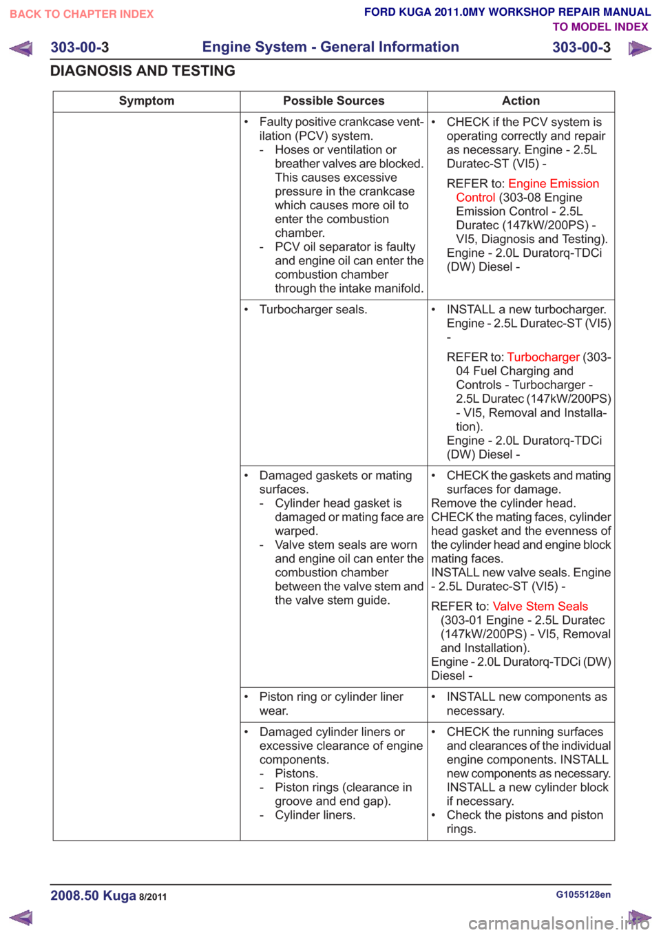
Action
Possible Sources
Symptom
• CHECK if the PCV system isoperating correctly and repair
as necessary. Engine - 2.5L
Duratec-ST (VI5) -
REFER to: Engine Emission
Control (303-08 Engine
Emission Control - 2.5L
Duratec (147kW/200PS) -
VI5, Diagnosis and Testing).
Engine - 2.0L Duratorq-TDCi
(DW) Diesel -
• Faulty positive crankcase vent-
ilation (PCV) system.
- Hoses or ventilation orbreather valves are blocked.
This causes excessive
pressure in the crankcase
which causes more oil to
enter the combustion
chamber.
- PCV oil separator is faulty and engine oil can enter the
combustion chamber
through the intake manifold.
• INSTALL a new turbocharger.Engine - 2.5L Duratec-ST (VI5)
-
REFER to: Turbocharger (303-
04 Fuel Charging and
Controls - Turbocharger -
2.5L Duratec (147kW/200PS)
- VI5, Removal and Installa-
tion).
Engine - 2.0L Duratorq-TDCi
(DW) Diesel -
• Turbocharger seals.
• CHECK the gaskets and matingsurfaces for damage.
Remove the cylinder head.
CHECK the mating faces, cylinder
head gasket and the evenness of
the cylinder head and engine block
mating faces.
INSTALL new valve seals. Engine
- 2.5L Duratec-ST (VI5) -
REFER to: Valve Stem Seals
(303-01 Engine - 2.5L Duratec
(147kW/200PS) - VI5, Removal
and Installation).
Engine - 2.0L Duratorq-TDCi (DW)
Diesel -
• Damaged gaskets or mating
surfaces.
- Cylinder head gasket isdamaged or mating face are
warped.
- Valve stem seals are worn and engine oil can enter the
combustion chamber
between the valve stem and
the valve stem guide.
• INSTALL new components asnecessary.
• Piston ring or cylinder liner
wear.
• CHECK the running surfacesand clearances of the individual
engine components. INSTALL
new components as necessary.
INSTALL a new cylinder block
if necessary.
• Check the pistons and piston rings.
• Damaged cylinder liners or
excessive clearance of engine
components.
- Pistons.
- Piston rings (clearance ingroove and end gap).
- Cylinder liners.
G1055128en2008.50 Kuga8/2011
303-00- 3
Engine System - General Information
303-00- 3
DIAGNOSIS AND TESTING
TO MODEL INDEX
BACK TO CHAPTER INDEX
FORD KUGA 2011.0MY WORKSHOP REPAIR MANUAL
Page 1520 of 2057
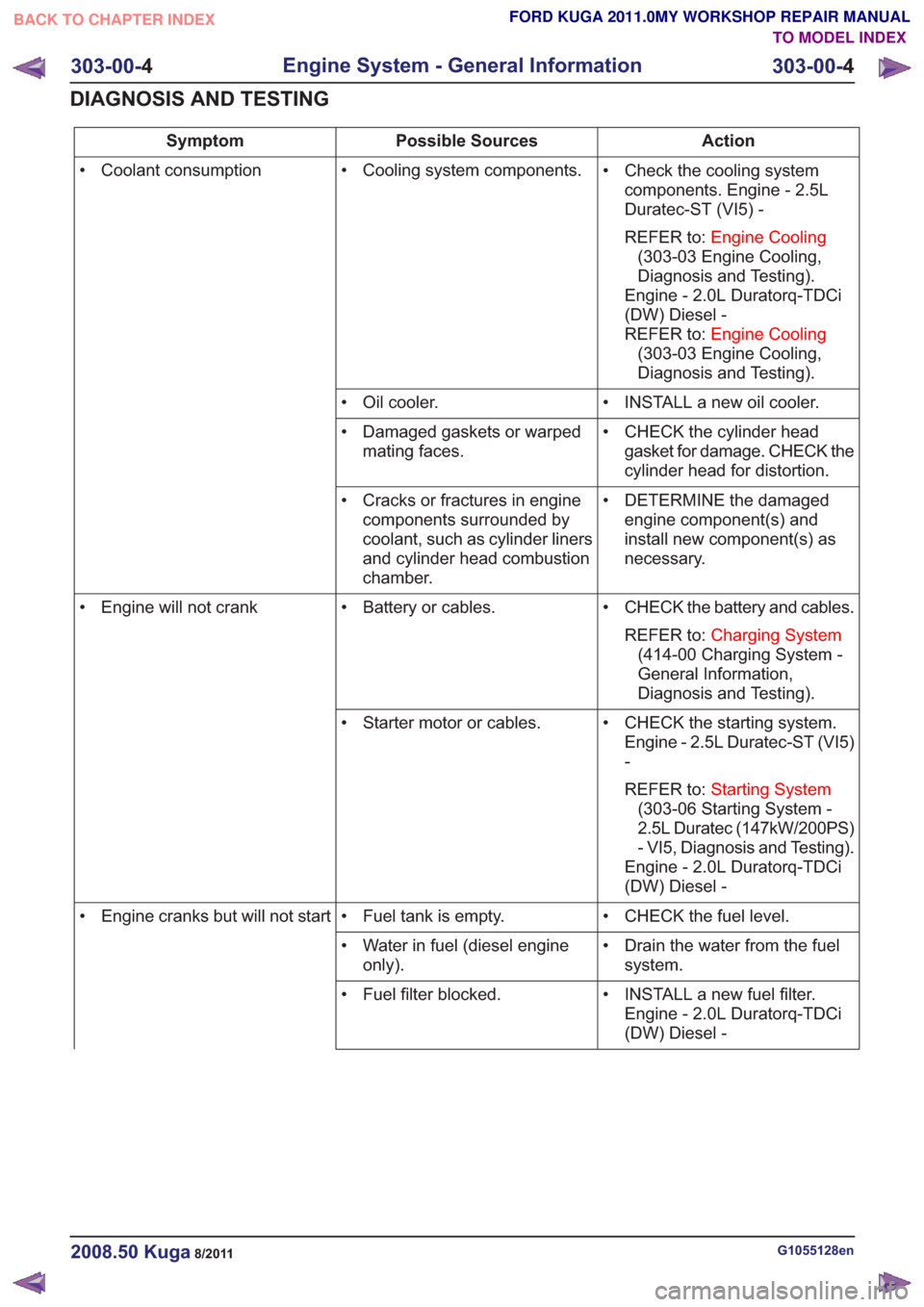
Action
Possible Sources
Symptom
• Check the cooling systemcomponents. Engine - 2.5L
Duratec-ST (VI5) -
REFER to: Engine Cooling
(303-03 Engine Cooling,
Diagnosis and Testing).
Engine - 2.0L Duratorq-TDCi
(DW) Diesel -
REFER to: Engine Cooling
(303-03 Engine Cooling,
Diagnosis and Testing).
• Cooling system components.
• Coolant consumption
• INSTALL a new oil cooler.
• Oil cooler.
• CHECK the cylinder headgasket for damage. CHECK the
cylinder head for distortion.
• Damaged gaskets or warped
mating faces.
• DETERMINE the damagedengine component(s) and
install new component(s) as
necessary.
• Cracks or fractures in engine
components surrounded by
coolant, such as cylinder liners
and cylinder head combustion
chamber.
• CHECK the battery and cables.REFER to: Charging System
(414-00 Charging System -
General Information,
Diagnosis and Testing).
• Battery or cables.
• Engine will not crank
• CHECK the starting system.Engine - 2.5L Duratec-ST (VI5)
-
REFER to: Starting System
(303-06 Starting System -
2.5L Duratec (147kW/200PS)
- VI5, Diagnosis and Testing).
Engine - 2.0L Duratorq-TDCi
(DW) Diesel -
• Starter motor or cables.
• CHECK the fuel level.
• Fuel tank is empty.
• Engine cranks but will not start
• Drain the water from the fuelsystem.
• Water in fuel (diesel engine
only).
• INSTALL a new fuel filter.Engine - 2.0L Duratorq-TDCi
(DW) Diesel -
• Fuel filter blocked.
G1055128en2008.50 Kuga8/2011
303-00-
4
Engine System - General Information
303-00- 4
DIAGNOSIS AND TESTING
TO MODEL INDEX
BACK TO CHAPTER INDEX
FORD KUGA 2011.0MY WORKSHOP REPAIR MANUAL