2011 FORD KUGA Compressor
[x] Cancel search: CompressorPage 1722 of 2057
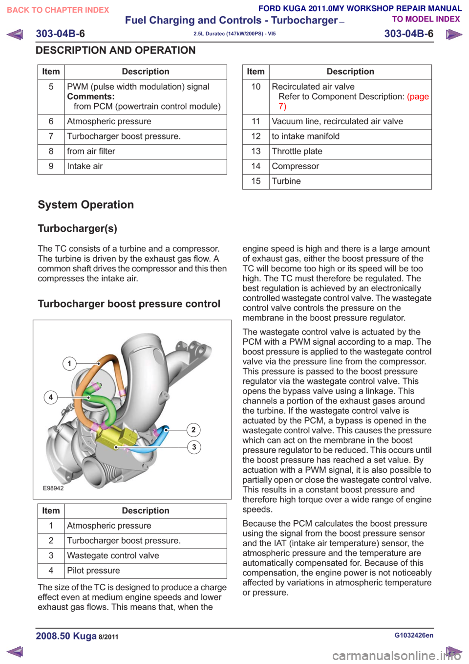
Description
Item
PWM (pulse width modulation) signal
Comments:from PCM (powertrain control module)
5
Atmospheric pressure
6
Turbocharger boost pressure.
7
from air filter
8
Intake air
9Description
Item
Recirculated air valveRefertoComponentDescription:(page
7)
10
Vacuum line, recirculated air valve
11
to intake manifold
12
Throttle plate
13
Compressor
14
Turbine
15
System Operation
Turbocharger(s)
The TC consists of a turbine and a compressor.
The turbine is driven by the exhaust gas flow. A
common shaft drives the compressor and this then
compresses the intake air.
Turbocharger boost pressure control
E98942
1
2
3
4
Description
Item
Atmospheric pressure
1
Turbocharger boost pressure.
2
Wastegate control valve
3
Pilot pressure
4
The size of the TC is designed to produce a charge
effect even at medium engine speeds and lower
exhaust gas flows. This means that, when the engine speed is high and there is a large amount
of exhaust gas, either the boost pressure of the
TC will become too high or its speed will be too
high. The TC must therefore be regulated. The
best regulation is achieved by an electronically
controlled wastegate control valve. The wastegate
control valve controls the pressure on the
membrane in the boost pressure regulator.
The wastegate control valve is actuated by the
PCM with a PWM signal according to a map. The
boost pressure is applied to the wastegate control
valve via the pressure line from the compressor.
This pressure is passed to the boost pressure
regulator via the wastegate control valve. This
opens the bypass valve using a linkage. This
channels a portion of the exhaust gases around
the turbine. If the wastegate control valve is
actuated by the PCM, a bypass is opened in the
wastegate control valve. This causes the pressure
which can act on the membrane in the boost
pressure regulator to be reduced. This occurs until
the boost pressure has reached a set value. By
actuation with a PWM signal, it is also possible to
partially open or close the wastegate control valve.
This results in a constant boost pressure and
therefore high torque over a wide range of engine
speeds.
Because the PCM calculates the boost pressure
using the signal from the boost pressure sensor
and the IAT (intake air temperature) sensor, the
atmospheric pressure and the temperature are
automatically compensated for. Because of this
compensation, the engine power is not noticeably
affected by variations in atmospheric temperature
or pressure.
G1032426en2008.50 Kuga8/2011
303-04B-
6
Fuel Charging and Controls - Turbocharger
—
2.5L Duratec (147kW/200PS) - VI5
303-04B- 6
DESCRIPTION AND OPERATION
TO MODEL INDEX
BACK TO CHAPTER INDEX
FORD KUGA 2011.0MY WORKSHOP REPAIR MANUAL
Page 1723 of 2057
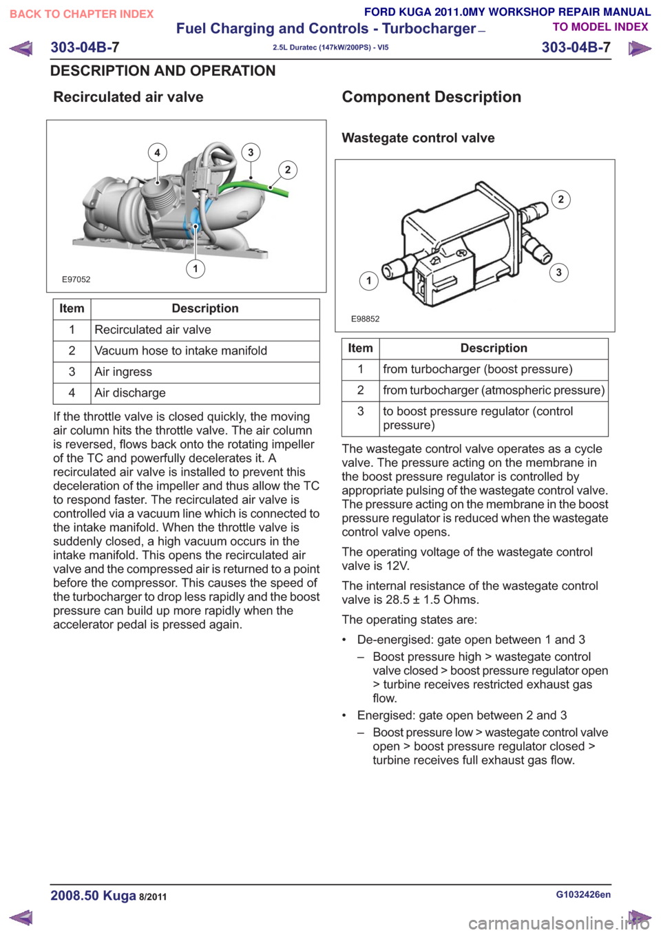
Recirculated air valve
E97052
43
2
1
Description
Item
Recirculated air valve
1
Vacuum hose to intake manifold
2
Air ingress
3
Air discharge
4
If the throttle valve is closed quickly, the moving
air column hits the throttle valve. The air column
is reversed, flows back onto the rotating impeller
of the TC and powerfully decelerates it. A
recirculated air valve is installed to prevent this
deceleration of the impeller and thus allow the TC
to respond faster. The recirculated air valve is
controlled via a vacuum line which is connected to
the intake manifold. When the throttle valve is
suddenly closed, a high vacuum occurs in the
intake manifold. This opens the recirculated air
valve and the compressed air is returned to a point
before the compressor. This causes the speed of
the turbocharger to drop less rapidly and the boost
pressure can build up more rapidly when the
accelerator pedal is pressed again.
Component Description
Wastegate control valve
1
2
3
E98852
Description
Item
from turbocharger (boost pressure)
1
from turbocharger (atmospheric pressure)
2
to boost pressure regulator (control
pressure)
3
The wastegate control valve operates as a cycle
valve. The pressure acting on the membrane in
the boost pressure regulator is controlled by
appropriate pulsing of the wastegate control valve.
The pressure acting on the membrane in the boost
pressure regulator is reduced when the wastegate
control valve opens.
The operating voltage of the wastegate control
valve is 12V.
The internal resistance of the wastegate control
valve is 28.5 ± 1.5 Ohms.
The operating states are:
• De-energised: gate open between 1 and 3 – Boost pressure high > wastegate controlvalve closed > boost pressure regulator open
> turbine receives restricted exhaust gas
flow.
• Energised: gate open between 2 and 3 – Boost pressure low > wastegate control valveopen > boost pressure regulator closed >
turbine receives full exhaust gas flow.
G1032426en2008.50 Kuga8/2011
303-04B- 7
Fuel Charging and Controls - Turbocharger
—
2.5L Duratec (147kW/200PS) - VI5
303-04B- 7
DESCRIPTION AND OPERATION
TO MODEL INDEX
BACK TO CHAPTER INDEX
FORD KUGA 2011.0MY WORKSHOP REPAIR MANUAL
Page 1726 of 2057
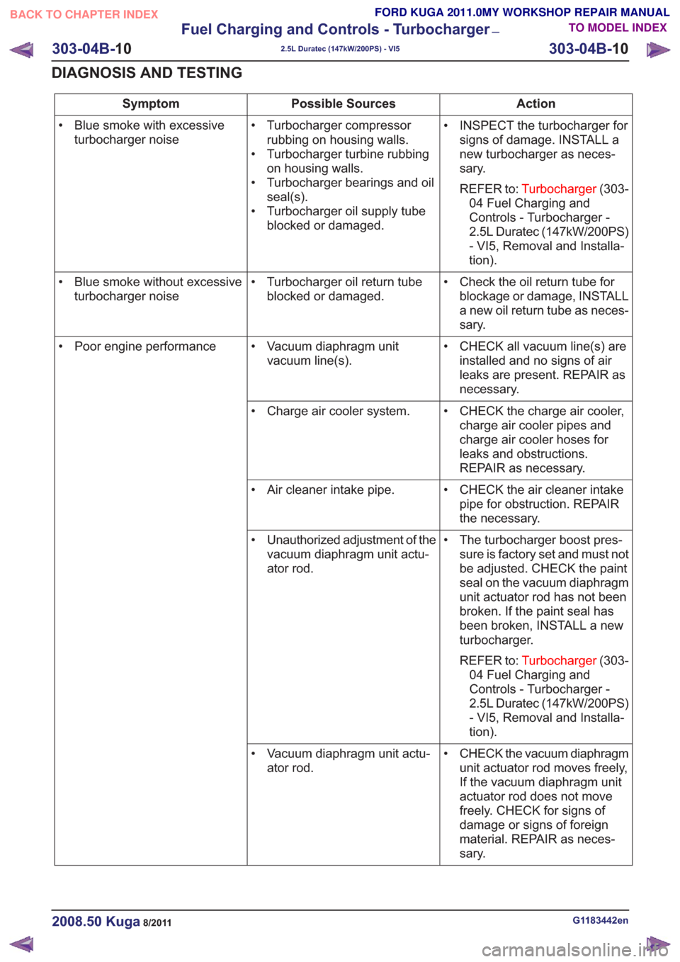
Action
Possible Sources
Symptom
• INSPECT the turbocharger forsigns of damage. INSTALL a
new turbocharger as neces-
sary.
REFER to: Turbocharger (303-
04 Fuel Charging and
Controls - Turbocharger -
2.5L Duratec (147kW/200PS)
- VI5, Removal and Installa-
tion).
• Turbocharger compressor
rubbing on housing walls.
• Turbocharger turbine rubbing on housing walls.
• Turbocharger bearings and oil seal(s).
• Turbocharger oil supply tube blocked or damaged.
• Blue smoke with excessive
turbocharger noise
• Check the oil return tube forblockage or damage, INSTALL
a new oil return tube as neces-
sary.
• Turbocharger oil return tube
blocked or damaged.
• Blue smoke without excessive
turbocharger noise
• CHECK all vacuum line(s) areinstalled and no signs of air
leaks are present. REPAIR as
necessary.
• Vacuum diaphragm unit
vacuum line(s).
• Poor engine performance
• CHECK the charge air cooler,charge air cooler pipes and
charge air cooler hoses for
leaks and obstructions.
REPAIR as necessary.
• Charge air cooler system.
• CHECK the air cleaner intakepipe for obstruction. REPAIR
the necessary.
• Air cleaner intake pipe.
• The turbocharger boost pres-sure is factory set and must not
be adjusted. CHECK the paint
seal on the vacuum diaphragm
unit actuator rod has not been
broken. If the paint seal has
been broken, INSTALL a new
turbocharger.
REFER to: Turbocharger (303-
04 Fuel Charging and
Controls - Turbocharger -
2.5L Duratec (147kW/200PS)
- VI5, Removal and Installa-
tion).
• Unauthorized adjustment of the
vacuum diaphragm unit actu-
ator rod.
• CHECK the vacuum diaphragmunit actuator rod moves freely,
If the vacuum diaphragm unit
actuator rod does not move
freely. CHECK for signs of
damage or signs of foreign
material. REPAIR as neces-
sary.
• Vacuum diaphragm unit actu-
ator rod.
G1183442en2008.50 Kuga8/2011
303-04B- 10
Fuel Charging and Controls - Turbocharger
—
2.5L Duratec (147kW/200PS) - VI5
303-04B- 10
DIAGNOSIS AND TESTING
TO MODEL INDEX
BACK TO CHAPTER INDEX
FORD KUGA 2011.0MY WORKSHOP REPAIR MANUAL
Page 1731 of 2057
SECTION 303-05 Accessory Drive— 2.5L Duratec (147kW/200PS) - VI5
VEHICLE APPLICATION:2008.50 Kuga
PA G E
CONTENTS
DESCRIPTION AND OPERATION
303-05-2
Accessory Drive ........................................................................\
..........................................
DIAGNOSIS AND TESTING 303-05-4
Accessory Drive ........................................................................\
..........................................
303-05-4
Inspection and Verification ........................................................................\
..........................
303-05-4
Accessory Drive Belt Concerns ........................................................................\
..................
303-05-6
Symptom Chart ........................................................................\
...........................................
303-05-9
Component Tests ........................................................................\
........................................
REMOVAL AND INSTALLATION 303-05-11
(21 569 0)
Accessory Drive Belt Tensioner ......................................................................
303-05-12
(21 567 0)
Accessory Drive Belt ........................................................................\
..............
303-05-13
(21 567 0)
Air Conditioning (A/C) Compressor Belt .........................................................
303-05-14
Air Conditioning (A/C) Compressor Belt Tensioner ............................................................
303-05-1
Accessory Drive— 2.5L Duratec (147kW/200PS) - VI5303-05-
1
.
TO MODEL INDEX
BACK TO CHAPTER INDEX
FORD KUGA 2011.0MY WORKSHOP REPAIR MANUAL
Page 1732 of 2057
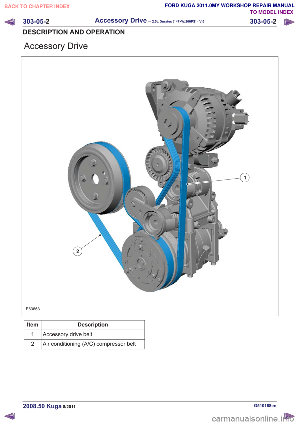
Accessory Drive
2
1
E63663
Description
Item
Accessory drive belt
1
Air conditioning (A/C) compressor belt
2
G510168en2008.50 Kuga8/2011
303-05- 2
Accessory Drive— 2.5L Duratec (147kW/200PS) - VI5303-05-
2
DESCRIPTION AND OPERATION
TO MODEL INDEX
BACK TO CHAPTER INDEX
FORD KUGA 2011.0MY WORKSHOP REPAIR MANUAL
Page 1733 of 2057
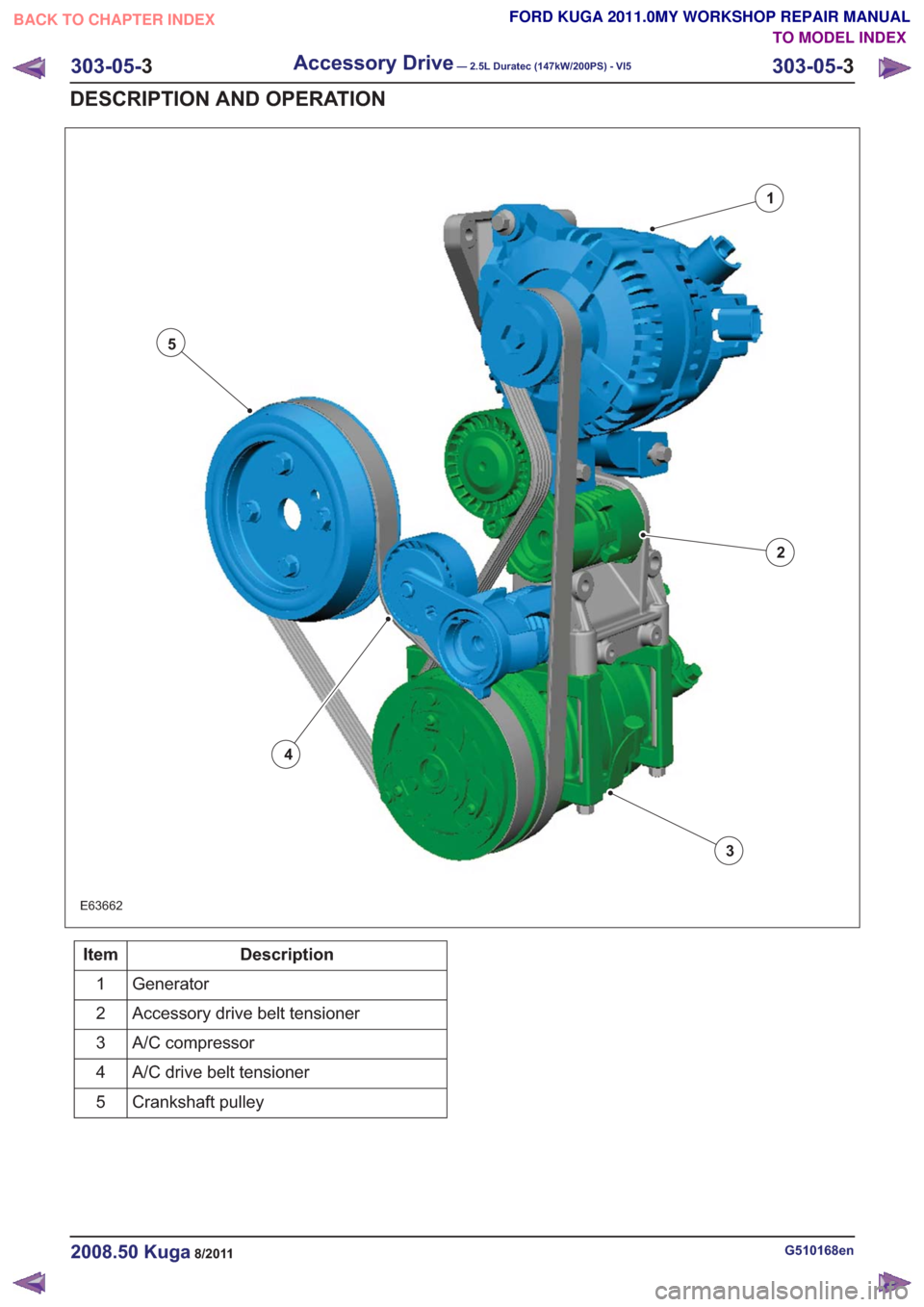
2
1
3
4
5
E63662
Description
Item
Generator
1
Accessory drive belt tensioner
2
A/C compressor
3
A/C drive belt tensioner
4
Crankshaft pulley
5
G510168en2008.50 Kuga8/2011
303-05- 3
Accessory Drive— 2.5L Duratec (147kW/200PS) - VI5303-05-
3
DESCRIPTION AND OPERATION
TO MODEL INDEX
BACK TO CHAPTER INDEX
FORD KUGA 2011.0MY WORKSHOP REPAIR MANUAL
Page 1734 of 2057
Accessory Drive
Inspection and Verification
1. Verify the customer concern.
2. Visually inspect for obvious signs of mechanicaldamage.
Visual Inspection Chart
Mechanical
– Damaged or contaminated accessory drive belt or air conditioning (A/C) compressor belt
– Damaged or contaminated pulley(s)
– Incorrect accessory drive belt or A/C compressor belt
– Incorrect fitment of the accessory drive belt or A/C compressor belt
– Accessory drive belt tensioner
– Accessory drive belt idler pulley
– Generator
– A/C compressor
– A/C compressor belt tensioner
– Pulley(s)
– Loose hardware
3. If an obvious cause for an observed or reported concern is found, correct the cause (if possible)
before proceeding to the next step.
Accessory Drive Belt Concerns
CAUTION: Do not lubricate the accessory
drive belt, accessory drive belt tensioner(s)
or idler pulley(s) as potential damage to
the accessory drive belt material
construction, accessory drive belt
tensioner damping mechanism, accessory
drive belt tensioner pulley bearing and idler
pulley(s) bearing may occur.
NOTE: All the diagnosis and testing information
contained within this procedure can be used for
the accessory drive belt and the A/C compressor
belt.
Cracking
Accessory drive belts are made from rubber which
hardens with time and can develop cracks. As the
accessory drive belt runs on the back of some of
the pulleys, the cracks are opened up. Small cracks
are not considered to be a failure of the accessory drive belt. Only if the crack is deep enough to reach
the bottom of the groove to expose the cord or any
chunks are found to be missing from the accessory
drive belt, is the accessory drive belt condition
considered to be unacceptable.
1. Check the accessory drive belt for cracks. If the
damage exceeds the acceptable limit, install a
new accessory drive belt.
REFER to: Accessory Drive Belt (303-05
Accessory Drive - 2.5L Duratec
(147kW/200PS) - VI5, Removal and
Installation).
and/or
REFER to: Air Conditioning (A/C) Compressor
Belt (303-05 Accessory Drive - 2.5L Duratec
(147kW/200PS) - VI5, Removal and
Installation).
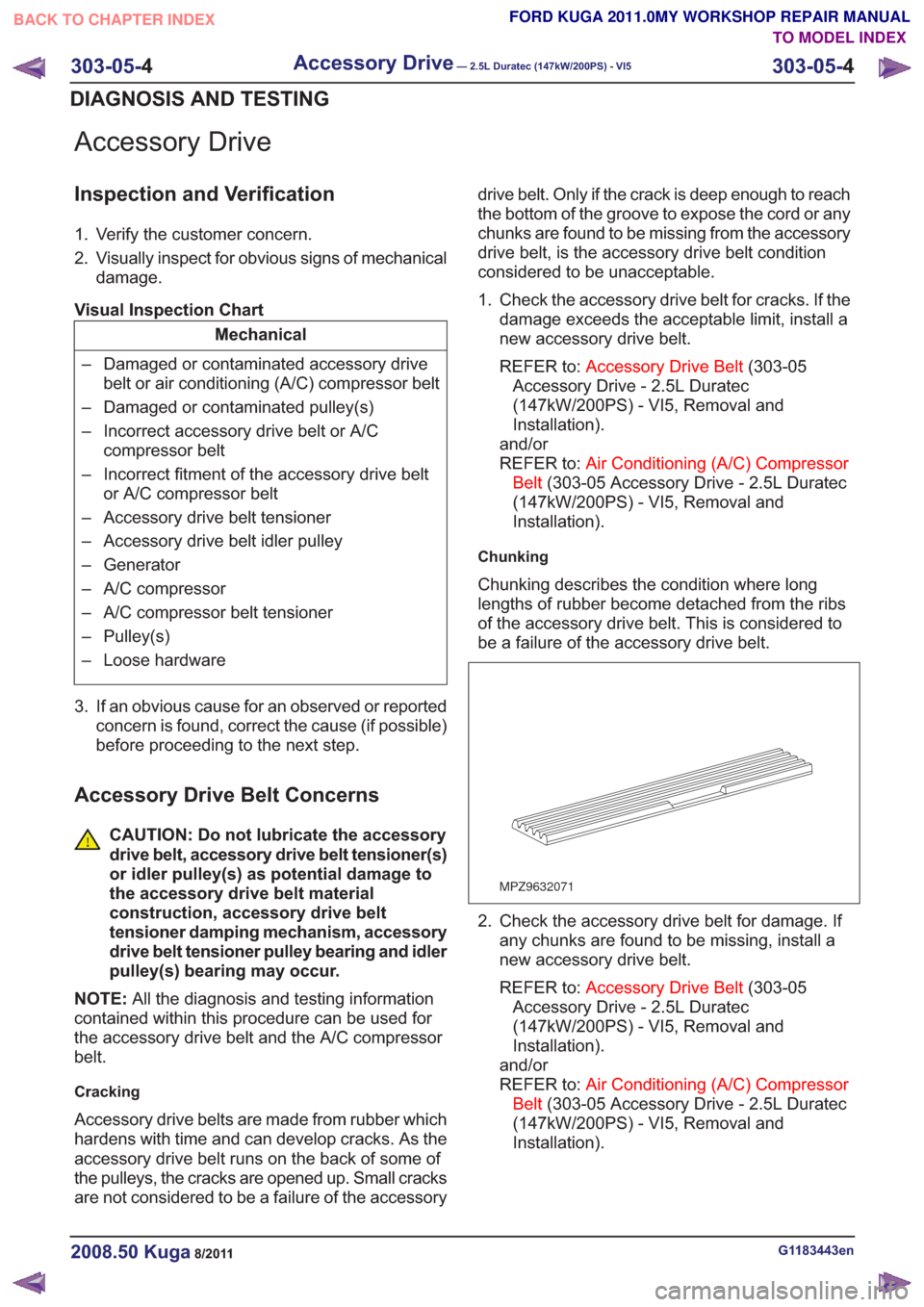
Chunking
Chunking describes the condition where long
lengths of rubber become detached from the ribs
of the accessory drive belt. This is considered to
be a failure of the accessory drive belt.
MPZ9632071
2. Check the accessory drive belt for damage. If any chunks are found to be missing, install a
new accessory drive belt.
REFER to: Accessory Drive Belt (303-05
Accessory Drive - 2.5L Duratec
(147kW/200PS) - VI5, Removal and
Installation).
and/or
REFER to: Air Conditioning (A/C) Compressor
Belt (303-05 Accessory Drive - 2.5L Duratec
(147kW/200PS) - VI5, Removal and
Installation).
G1183443en2008.50 Kuga8/2011
303-05- 4
Accessory Drive— 2.5L Duratec (147kW/200PS) - VI5303-05-
4
DIAGNOSIS AND TESTING
TO MODEL INDEX
BACK TO CHAPTER INDEX
FORD KUGA 2011.0MY WORKSHOP REPAIR MANUAL
Page 1735 of 2057
Pilling
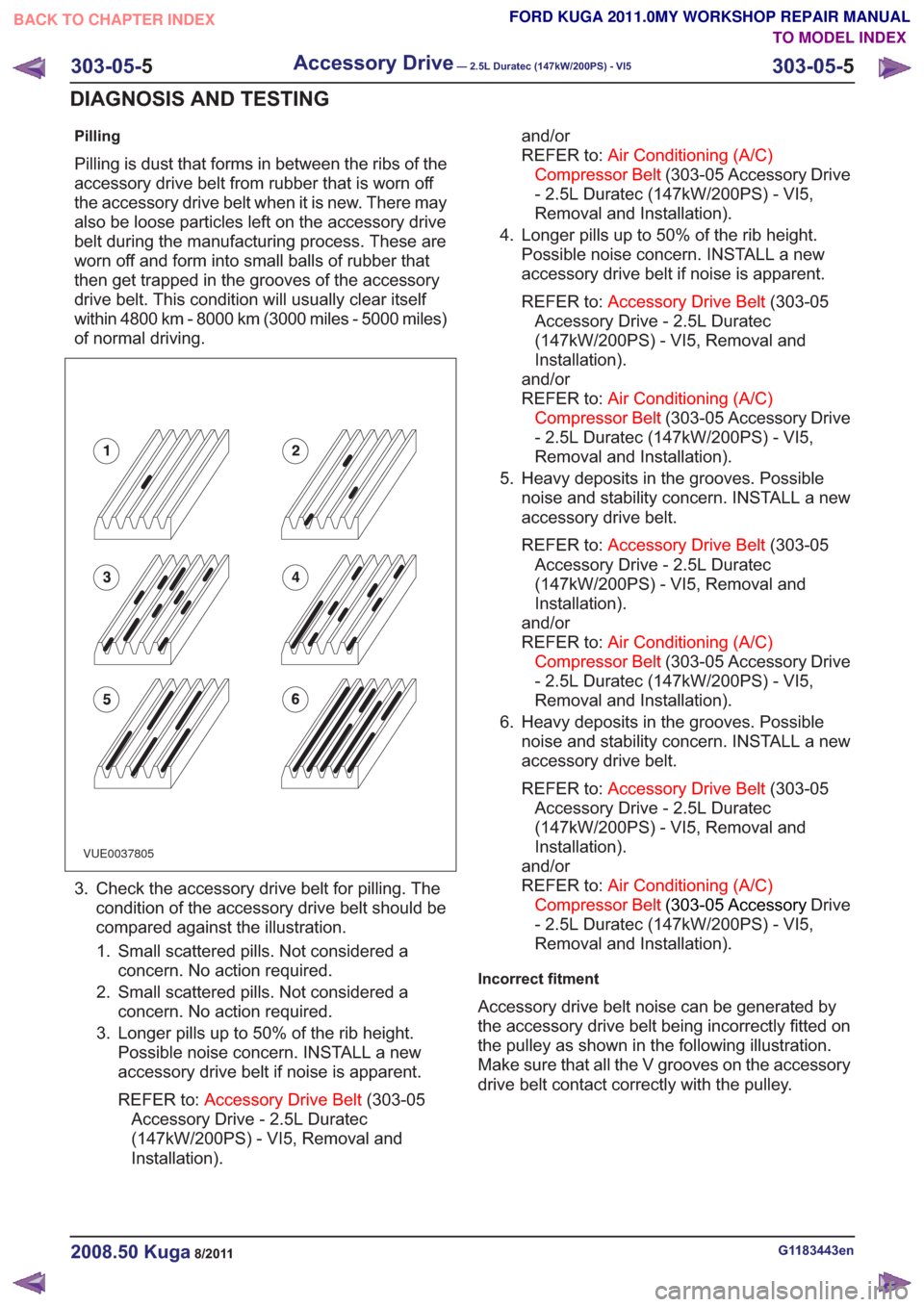
Pilling is dust that forms in between the ribs of the
accessory drive belt from rubber that is worn off
the accessory drive belt when it is new. There may
also be loose particles left on the accessory drive
belt during the manufacturing process. These are
worn off and form into small balls of rubber that
then get trapped in the grooves of the accessory
drive belt. This condition will usually clear itself
within 4800 km - 8000 km (3000 miles - 5000 miles)
of normal driving.
VUE0037805
3. Check the accessory drive belt for pilling. Thecondition of the accessory drive belt should be
compared against the illustration.
1. Small scattered pills. Not considered a concern. No action required.
2. Small scattered pills. Not considered a concern. No action required.
3. Longer pills up to 50% of the rib height. Possible noise concern. INSTALL a new
accessory drive belt if noise is apparent.
REFER to: Accessory Drive Belt (303-05
Accessory Drive - 2.5L Duratec
(147kW/200PS) - VI5, Removal and
Installation). and/or
REFER to:
Air Conditioning (A/C)
Compressor Belt (303-05 Accessory Drive
- 2.5L Duratec (147kW/200PS) - VI5,
Removal and Installation).
4. Longer pills up to 50% of the rib height. Possible noise concern. INSTALL a new
accessory drive belt if noise is apparent.
REFER to: Accessory Drive Belt (303-05
Accessory Drive - 2.5L Duratec
(147kW/200PS) - VI5, Removal and
Installation).
and/or
REFER to: Air Conditioning (A/C)
Compressor Belt (303-05 Accessory Drive
- 2.5L Duratec (147kW/200PS) - VI5,
Removal and Installation).
5. Heavy deposits in the grooves. Possible noise and stability concern. INSTALL a new
accessory drive belt.
REFER to: Accessory Drive Belt (303-05
Accessory Drive - 2.5L Duratec
(147kW/200PS) - VI5, Removal and
Installation).
and/or
REFER to: Air Conditioning (A/C)
Compressor Belt (303-05 Accessory Drive
- 2.5L Duratec (147kW/200PS) - VI5,
Removal and Installation).
6. Heavy deposits in the grooves. Possible noise and stability concern. INSTALL a new
accessory drive belt.
REFER to: Accessory Drive Belt (303-05
Accessory Drive - 2.5L Duratec
(147kW/200PS) - VI5, Removal and
Installation).
and/or
REFER to: Air Conditioning (A/C)
Compressor Belt (303-05 AccessoryDrive
- 2.5L Duratec (147kW/200PS) - VI5,
Removal and Installation).
Incorrect fitment
Accessory drive belt noise can be generated by
the accessory drive belt being incorrectly fitted on
the pulley as shown in the following illustration.
Make sure that all the V grooves on the accessory
drive belt contact correctly with the pulley.
G1183443en2008.50 Kuga8/2011
303-05- 5
Accessory Drive— 2.5L Duratec (147kW/200PS) - VI5303-05-
5
DIAGNOSIS AND TESTING
TO MODEL INDEX
BACK TO CHAPTER INDEX
FORD KUGA 2011.0MY WORKSHOP REPAIR MANUAL