2011 FORD KUGA CAN BUS
[x] Cancel search: CAN BUSPage 458 of 2057

Turn signals
Description
Item
External mirror housing
1
Turn signals
2
The GEM switches the direction indicators and the
direction indicator side repeaters on.
The GEM sends a signal to the instrument cluster
via the CAN bus to switch on the relevant turn
indicator and the acoustic signal.
The signals from the hazard flasher switch and
from the multifunction switch are transmitted to the
GEM via a wiring connection.
The turn signals and the warning lamp flash at a
specified frequency and, in the case of failure of a
turn signal, the frequency is doubled.
The turn signal lamps also have a one-touch lane
change function. If the multifunction lever is
pressed just slightly then the relevant turn signal
lamp is actuated 3 times by the GEM.
Interior lighting
Depending on the vehicle specification, the interior
lighting includes:
• Left and right-hand footwell lamps
• Overhead lights at front and rear
Depending on the vehicle specification, the
switchable interior lighting includes:
• Map lights
• Mirror lights in sun visors
• Glove compartment lamp
• Luggage compartment lamp
The front and rear overhead lights are switched on
by the GEM. The interior lighting is switched on if one of the
following conditions is satisfied:
One of the vehicle's doors is opened.
The ignition key is in the "0" or "I" position and the
vehicle is unlocked.
The ignition key is turned from the "II" to the "I" or
"0" position.
The interior lighting is switched off when all of the
doors are closed and one of the following
conditions is satisfied:
• 25 seconds have elapsed since the last door
was closed.
• The ignition key is turned from the "0" or "I" to the "II" position.
• The ignition key is in the "0" or "I" position while the vehicle is locked.
The dimmer function is not used if the interior
lighting is switched off via the battery protection
function.
Heated windscreen
The heated windshield is switched on by the GEM
under the following conditions:
• The heated windshield switch is operated, the ignition switch is in position "II" and the charge
warning lamp is switched off.
• The "Defrost" function of the two-zone air conditioning has been activated, the ignition
switch is in the position "II" and the charge
warning lamp is off.
• The battery voltage has exceeded 16 V for more
than 20 seconds (power management strategy).
Manual requests for switching off the heated
windshield by pressing the switch are ignored
at this time.
• The engine was started at an outside air temperature below 4°C and an engine
temperature below 65°. Manual requests for
switching off the heated windshield by pressing
the switch are accepted.
NOTE: If the battery voltage returns to the normal
range, the disabling of the heated windshield is
switched off. It is then switched off.
The heated windshield is switched off by the GEM
under the following conditions: G1030788en
2008.50 Kuga 8/2011 419-10-8
Multifunction Electronic Modules
419-10-8
DESCRIPTION AND OPERATIONTO MODEL INDEX
BACK TO CHAPTER INDEX
FORD KUGA 2011.0MY WORKSHOP REPAIR MANUAL12E98941
Page 459 of 2057

• 4 minutes have elapsed since the button for the
heated windshield was pressed.
• The ignition switch is turned to the "I" or "0" position.
• The "Defrost" function is deactivated or the switch for the heated windscreen is pressed
again while the heated windscreen is still
switched on.
• The charging system warning indicator is switched on.
• The battery voltage falls below the threshold value for low battery voltage for more than 20
seconds (power management strategy). Manual
requests for switching on the heated windshield
by pressing the switch are ignored at this time.
• More than 4 minutes have passed since starting
the engine.
Heated rear window and heated external
mirrors
The GEM transmits a request signal via the CAN
bus to the door modules to switch on the heated
exterior mirrors.
The heated rear window and the heated exterior
mirrors are switched on by the GEM under the
following conditions:
• The switch for the heated rear window is pressed and the ignition switch is in the "II"
position.
• The "defrost" function of the air conditioning is activated and the ignition switch is in the position
"II".
• The battery voltage has exceeded 16 V for more
than 20 seconds (power management strategy).
Manual requests to switch off the heated rear
window by pressing the button are ignored at
this time.
• The engine was started at an outside air temperature below 4°C and an engine
temperature below 65°. Manual requests for
switching off the heated rear window by pressing
the switch are accepted.
NOTE: If the battery voltage returns to the normal
range then the disabling of the heated rear window
is cancelled - the heated rear window is then in a
switched-off state.
The GEM transmits a request signal via the CAN
bus to the door modules to switch off the heated
exterior mirrors. The heated rear window and the heated exterior
mirrors are switched off by the GEM under the
following conditions
• 14 minutes have elapsed since the button for
the heated rear window was pressed.
• The ignition switch is turned to the position "0", "I" or "III".
• The switch for the heated rear window is pressed or the "defrost" function of the air
conditioning is deactivated while the heated rear
window is switched on.
• The battery voltage has dropped below 10.3 V for more than 20 seconds (power management
strategy). Manual requests for switching on the
heated rear window by pressing the switch are
ignored at this time.
• More than 14 minutes have passed since starting the engine.
Ambient air temperature
The ambient air temperature sensor is connected
via a cable to the GEM. It measures the outside
air temperature to an accuracy of around ±0.5 °C.
The GEM broadcasts the ambient air temperature
on the medium speed CAN bus, where it can be
evaluated by various systems.
Brake fluid level
The brake fluid level switch is connected via a
cable to the GEM.
The GEM transmits a message on the medium
speed CAN bus. The instrument cluster then
transfers this message to the high speed CAN bus
where it is made available for various other
functions.
Automatic headlamps
Refer to: Exterior Lighting (417-01 Exterior Lighting,
Description and Operation).
Combined rain sensor/light sensor
Refer to: Exterior Lighting (417-01 Exterior Lighting,
Description and Operation). G1030788en
2008.50 Kuga 8/2011 419-10-9
Multifunction Electronic Modules
419-10-9
DESCRIPTION AND OPERATIONTO MODEL INDEX
BACK TO CHAPTER INDEX
FORD KUGA 2011.0MY WORKSHOP REPAIR MANUAL
Page 1232 of 2057
Tire Pressure Monitoring System (TPMS) – Overview
Description of operation
The tire pressure monitoring system is able to
detect loss of air in a tire at an early stage and warn
the driver. Because it can only compare the
behavior of the tires with each other, it is not
possible to draw conclusions about the absolute
tire pressure. It is also not possible to monitor the
spare tire pressure. In order for the system to
operate correctly, the tire pressures must be
regularly checked and corrected and the system
subsequently initialized (see below).
The tire pressure monitoring system used here,
depending on the equipment level, is built into the
anti-lock braking system (ABS) as an extra function
and therefore does not have its own sensors.
The ABS module determines the loss of pressure
in the tires by calculation using the wheel speed
sensors of the ABS system. If a tire loses pressure,
its diameter decreases and the speed of the wheel
therefore increases. If the ABS module detects
such a loss in pressure, it sends a signal to the
instrument cluster via the CAN bus and a warning
message is displayed in the driver information
system. The warning threshold depends among
other things on the dimension of the tires being
used, the vehicle operating conditions and the
status at the last initialization. Since neither the
absolute tire pressure nor the position of the tire is
known, after a tire pressure warning the pressure
of all the tires must be checked and the system
re-initialized. If necessary, the cause of the loss of
pressure must be investigated.
Furthermore, regular pressure checks are
necessary. The system must be initialized after a
tire is changed, winter or summer tires fitted, the
pressures corrected or adjusted to suit the vehicle
load. This can be done by the driver using the
driver information system. For further information,
see: Owner’s Manual.
G1001290en2008.50 Kuga8/2011
204-04-5
Wheels and Tires
204-04- 5
DESCRIPTION AND OPERATION
TO MODEL INDEX
BACK TO CHAPTER INDEX
FORD KUGA 2011.0MY WORKSHOP REPAIR MANUAL
Page 1252 of 2057
General overview
Haldex clutches of the 3rd and 4th generations are
used in the Ford Kuga.
The development of the third generation Haldex
clutch represents a big step forward in modern
all-wheel technology. The Haldex clutch is
electro-hydraulically controlled. Additional
information is taken into consideration during
control tasks via the all-wheel drive control unit.
Slip alone is no longer decisive for the distribution
of the propulsive forces; the vehicle's driving
dynamics are also taken into consideration. The
control unit accesses the driving-related data via
the data bus. With this data, the control unit has
all the essential information about speed, cornering,
coasting or traction operation, and can optimally
react to every driving situation.
Compared with the previous generation, the 4th
generation Haldex clutches operate with higher
pressure and achieve shorter response times when
distributing the drive forces.
Advantages of the Haldex clutch:
• Permanent all-wheel drive withelectronically-controlled multi-plate clutch
• Fast response
• No straining when parking and manoeuvring
• Compatible with different tyres (e.g. emergency spare wheel)
• Fully combinable with driving dynamic control systems
The driveshaft is connected to the input shaft of
the Haldex clutch. Within the Haldex clutch, the
input shaft is separated from the output shaft to
the rear axle differential by means of a multi-plate
clutch. Torque is only transmitted to the rear axle
differential when the plate assembly of the Haldex
clutch is closed.
The multi-plate clutch is electro-hydraulically
controlled via the all-wheel drive control unit. For
ecological driving, the torque to the rear axle is reduced to a minimum up to a throttle position of
approx. 50%. A prerequisite for this is that there is
no difference in speed in the Haldex clutch between
the input and output shafts.
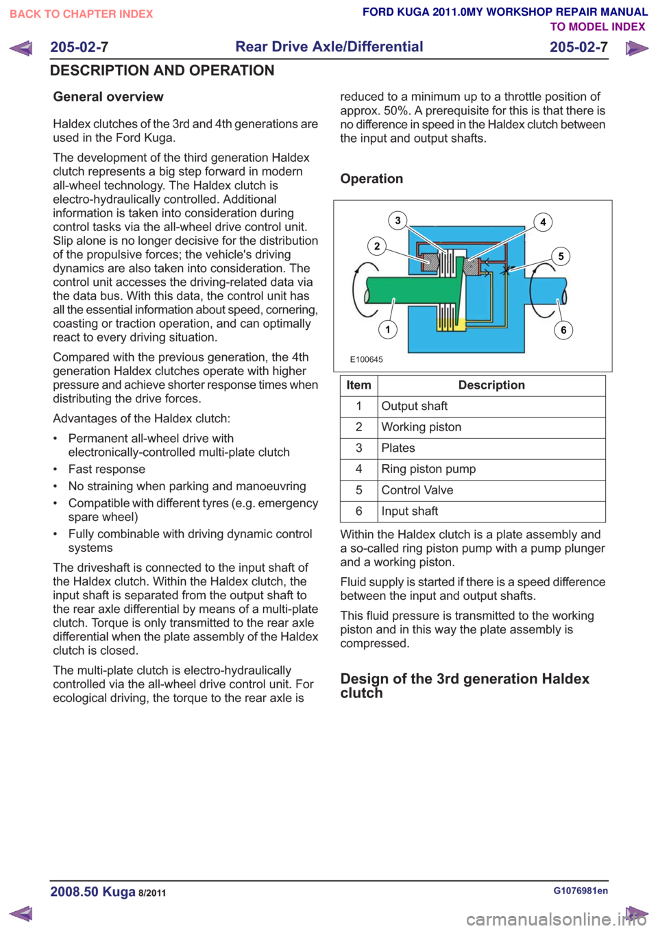
Operation
E100645
16
3
25
4
Description
Item
Output shaft
1
Working piston
2
Plates
3
Ring piston pump
4
Control Valve
5
Input shaft
6
Within the Haldex clutch is a plate assembly and
a so-called ring piston pump with a pump plunger
and a working piston.
Fluid supply is started if there is a speed difference
between the input and output shafts.
This fluid pressure is transmitted to the working
piston and in this way the plate assembly is
compressed.
Design of the 3rd generation Haldex
clutch
G1076981en2008.50 Kuga8/2011
205-02- 7
Rear Drive Axle/Differential
205-02- 7
DESCRIPTION AND OPERATION
TO MODEL INDEX
BACK TO CHAPTER INDEX
FORD KUGA 2011.0MY WORKSHOP REPAIR MANUAL
Page 1255 of 2057
All-wheel drive control unit
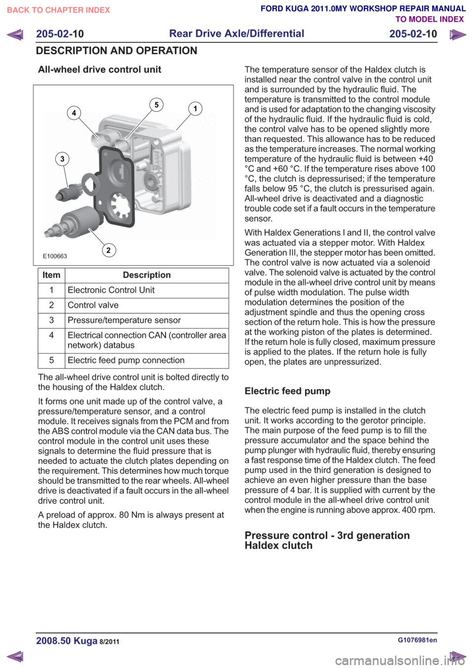
E100663
14
3
2
5
Description
Item
Electronic Control Unit
1
Control valve
2
Pressure/temperature sensor
3
Electrical connection CAN (controller area
network) databus
4
Electric feed pump connection
5
The all-wheel drive control unit is bolted directly to
the housing of the Haldex clutch.
It forms one unit made up of the control valve, a
pressure/temperature sensor, and a control
module. It receives signals from the PCM and from
the ABS control module via the CAN data bus. The
control module in the control unit uses these
signals to determine the fluid pressure that is
needed to actuate the clutch plates depending on
the requirement. This determines how much torque
should be transmitted to the rear wheels. All-wheel
drive is deactivated if a fault occurs in the all-wheel
drive control unit.
A preload of approx. 80 Nm is always present at
the Haldex clutch. The temperature sensor of the Haldex clutch is
installed near the control valve in the control unit
and is surrounded by the hydraulic fluid. The
temperature is transmitted to the control module
and is used for adaptation to the changing viscosity
of the hydraulic fluid. If the hydraulic fluid is cold,
the control valve has to be opened slightly more
than requested. This allowance has to be reduced
as the temperature increases. The normal working
temperature of the hydraulic fluid is between +40
°C and +60 °C. If the temperature rises above 100
°C, the clutch is depressurised; if the temperature
falls below 95 °C, the clutch is pressurised again.
All-wheel drive is deactivated and a diagnostic
trouble code set if a fault occurs in the temperature
sensor.
With Haldex Generations I and II, the control valve
was actuated via a stepper motor. With Haldex
Generation III, the stepper motor has been omitted.
The control valve is now actuated via a solenoid
valve. The solenoid valve is actuated by the control
module in the all-wheel drive control unit by means
of pulse width modulation. The pulse width
modulation determines the position of the
adjustment spindle and thus the opening cross
section of the return hole. This is how the pressure
at the working piston of the plates is determined.
If the return hole is fully closed, maximum pressure
is applied to the plates. If the return hole is fully
open, the plates are unpressurized.
Electric feed pump
The electric feed pump is installed in the clutch
unit. It works according to the gerotor principle.
The main purpose of the feed pump is to fill the
pressure accumulator and the space behind the
pump plunger with hydraulic fluid, thereby ensuring
a fast response time of the Haldex clutch. The feed
pump used in the third generation is designed to
achieve an even higher pressure than the base
pressure of 4 bar. It is supplied with current by the
control module in the all-wheel drive control unit
when the engine is running above approx. 400 rpm.
Pressure control - 3rd generation
Haldex clutch
G1076981en2008.50 Kuga8/2011
205-02-
10
Rear Drive Axle/Differential
205-02- 10
DESCRIPTION AND OPERATION
TO MODEL INDEX
BACK TO CHAPTER INDEX
FORD KUGA 2011.0MY WORKSHOP REPAIR MANUAL
Page 1353 of 2057
DETAILS/RESULTS/ACTIONS
TEST CONDITIONS
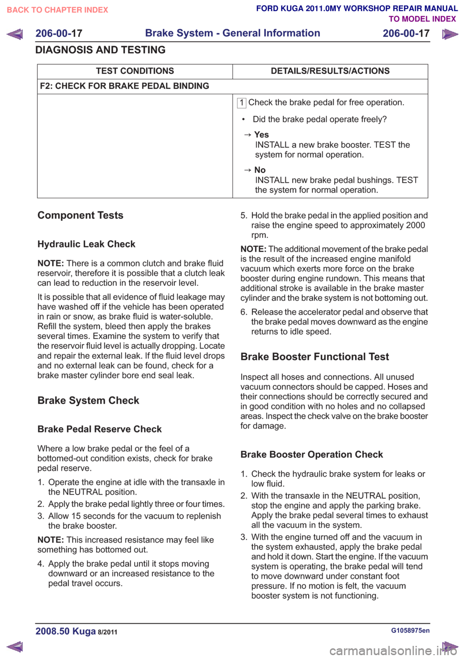
F2: CHECK FOR BRAKE PEDAL BINDING
1 Check the brake pedal for free operation.
• Did the brake pedal operate freely?
zYe s INSTALL a new brake booster. TEST the
system for normal operation.
zNoINSTALL new brake pedal bushings. TEST
the system for normal operation.
Component Tests
Hydraulic Leak Check
NOTE: There is a common clutch and brake fluid
reservoir, therefore it is possible that a clutch leak
can lead to reduction in the reservoir level.
It is possible that all evidence of fluid leakage may
have washed off if the vehicle has been operated
in rain or snow, as brake fluid is water-soluble.
Refill the system, bleed then apply the brakes
several times. Examine the system to verify that
the reservoir fluid level is actually dropping. Locate
and repair the external leak. If the fluid level drops
and no external leak can be found, check for a
brake master cylinder bore end seal leak.
Brake System Check
Brake Pedal Reserve Check
Where a low brake pedal or the feel of a
bottomed-out condition exists, check for brake
pedal reserve.
1. Operate the engine at idle with the transaxle in the NEUTRAL position.
2. Apply the brake pedal lightly three or four times.
3. Allow 15 seconds for the vacuum to replenish the brake booster.
NOTE: This increased resistance may feel like
something has bottomed out.
4. Apply the brake pedal until it stops moving downward or an increased resistance to the
pedal travel occurs. 5. Hold the brake pedal in the applied position and
raise the engine speed to approximately 2000
rpm.
NOTE: The additional movement of the brake pedal
is the result of the increased engine manifold
vacuum which exerts more force on the brake
booster during engine rundown. This means that
additional stroke is available in the brake master
cylinder and the brake system is not bottoming out.
6. Release the accelerator pedal and observe that the brake pedal moves downward as the engine
returns to idle speed.
Brake Booster Functional Test
Inspect all hoses and connections. All unused
vacuum connectors should be capped. Hoses and
their connections should be correctly secured and
in good condition with no holes and no collapsed
areas. Inspect the check valve on the brake booster
for damage.
Brake Booster Operation Check
1. Check the hydraulic brake system for leaks orlow fluid.
2. With the transaxle in the NEUTRAL position, stop the engine and apply the parking brake.
Apply the brake pedal several times to exhaust
all the vacuum in the system.
3. With the engine turned off and the vacuum in the system exhausted, apply the brake pedal
and hold it down. Start the engine. If the vacuum
system is operating, the brake pedal will tend
to move downward under constant foot
pressure. If no motion is felt, the vacuum
booster system is not functioning.
G1058975en2008.50 Kuga8/2011
206-00- 17
Brake System - General Information
206-00- 17
DIAGNOSIS AND TESTING
TO MODEL INDEX
BACK TO CHAPTER INDEX
FORD KUGA 2011.0MY WORKSHOP REPAIR MANUAL
Page 1429 of 2057
HCU to check for sudden actuation of the brakes.
With the brake pedal pressed, the ABS module
triggers emergency braking if the rate of increase
of hydraulic pressure exceeds the predetermined
limit.
If the brake pedal is pressed so hard that the ABS
becomes active on the front wheels then the ABS
control unit increases the pressure to the rear
wheel brakes up to the ABS intervention threshold.
EBA operation continues until the driver releases
the brake pedal sufficiently for the hydraulic
pressure in the HCU to drop below a threshold
value stored in the ABS module.
Trailer stability control:If the vehicle is ordered
with a trailer coupling then the Trailer Stability
Control function is integrated in the ESP. The ESP
detects snaking when driving with a trailer and
reduces the speed of the vehicle and trailer through
adapted braking and, if necessary, by also reducing
the engine output until the snaking movement of
the trailer is corrected.
Roll-over protection: The ESP dynamically
determines the tipping tendency of the vehicle and
works in conjunction with the EBA system to
prevent the vehicle from tipping over during
dynamic maneuvers like lane changing or while
negotiating bends.
Emergency brake light: The emergency brake
light automatically switches on the hazard flasher
system to warn drivers of other vehicles that
emergency braking is being initiated. Based on a
defined delay value, the ABS/ESP module sends
a signal to the generic electronic module (GEM)
via the CAN data bus. The GEM activates the
hazard flasher system, that then flashes 7 times.
Prerequisites for activation of the emergency brake
light are:
• The speed is higher than 50 km/h.
• The brake pedal is being actuated.
• The deceleration is greater than 9 m/s².
To prevent activation on snow or ice, for example,
the following prerequisites must be met:
• The speed is higher than 50 km/h.
• The brake pedal is being actuated.
• ABS regulation takes place.
• The deceleration is greater than 6 m/s².
Tire pressure monitoring system: The tire
pressure monitoring system used in the Kuga is
able to detect loss of air in a tire at an early stage
and warn the driver. Because it can only compare
the behaviour of the tyres with each other, it is not possible to draw conclusions about the absolute
tyre pressure. It is also not possible to monitor the
spare tyre pressure. In order for the system to
operate correctly, the tyre pressures must be
regularly checked and corrected and the system
subsequently initialised (see below).
The tire pressure monitoring system used here,
depending on the equipment level, is built into the
anti-lock braking system (ABS) as an extra function
and therefore does not have its own sensors.
The ABS module measures the loss of pressure
in the tyres by calculation using the wheel speed
sensors of the ABS system. If a tyre loses
pressure, its diameter decreases and the speed of
the wheel therefore increases. If the ABS module
detects such a loss in pressure, it sends a signal
to the instrument cluster via the CAN bus and a
warning message is displayed in the message
centre. The warning threshold depends among
other things on the dimension of the tyres being
used, the vehicle operating conditions and the
status at the last initialisation. Since neither the
absolute tyre pressure nor the position of the tyre
is known, the pressure of all the tyres must be
checked and the system re-initialised after a tyre
pressure warning. If necessary, the cause of the
loss of pressure must be investigated.
Regular tyre pressure checks are still necessary.
The system must be initialised after a tyre is
changed, winter or summer tyres fitted, the
pressures corrected or adjusted to suit the vehicle
load. This can be done by the driver using the
driver information system. For further information,
see: Owner’s Manual.
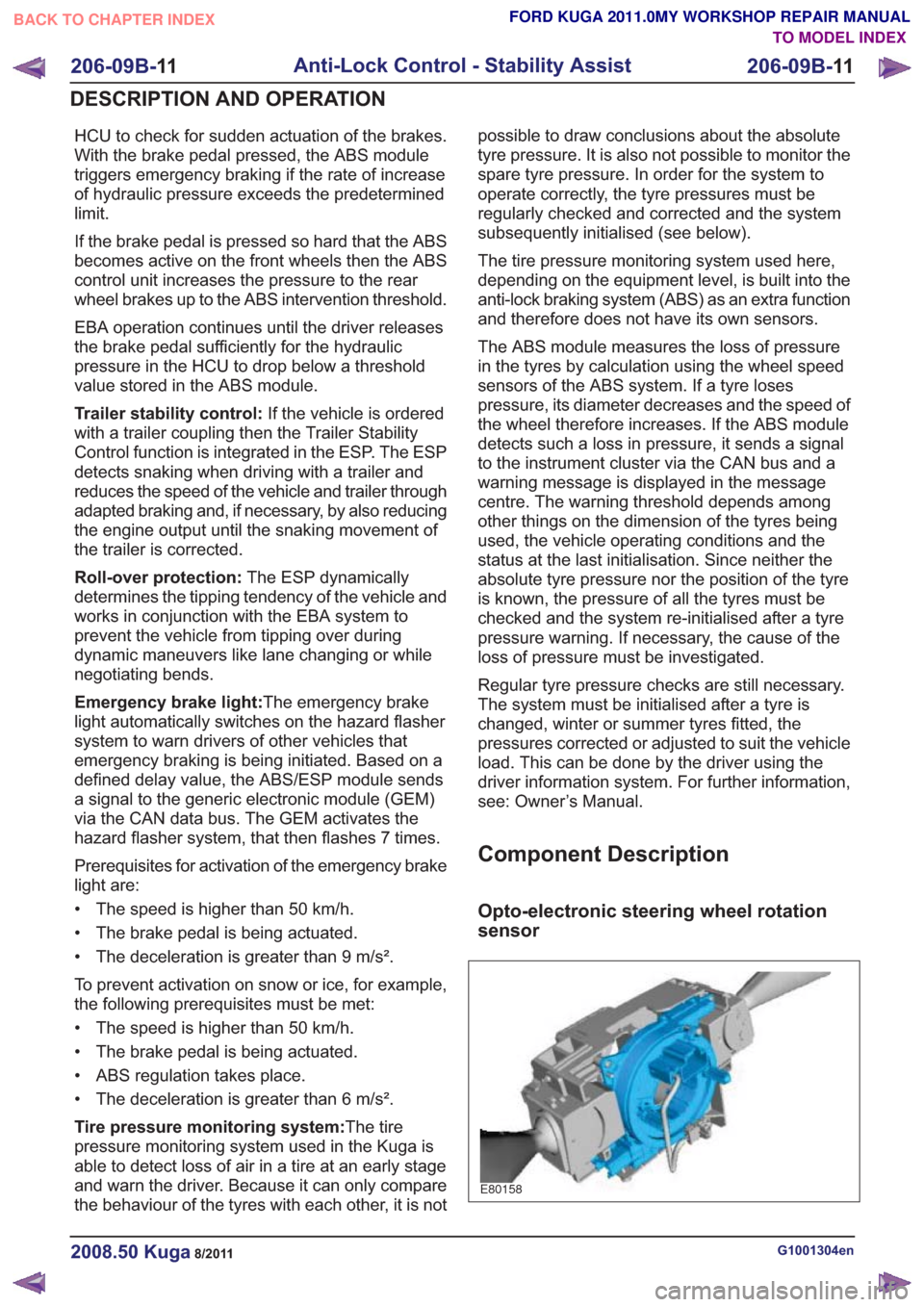
Component Description
Opto-electronic steering wheel rotation
sensor
E80158
G1001304en2008.50 Kuga8/2011
206-09B-
11
Anti-Lock Control - Stability Assist
206-09B- 11
DESCRIPTION AND OPERATION
TO MODEL INDEX
BACK TO CHAPTER INDEX
FORD KUGA 2011.0MY WORKSHOP REPAIR MANUAL
Page 1433 of 2057
generate a square wave output signal. The signal
acts in proportion to the rotational speed of the
sensor ring. The ABS sensor rings are built into
the seals in the front wheel bearings. The ABS
module evaluates the signals from all four sensors
to calculate a vehicle speed signal based on the
rotational speeds of all wheels. The road speed is
transmitted on the CAN bus. The powertrain controlmodule (PCM) uses this signal and the
programmed tire size to calculate the vehicle
speed. The calculated vehicle speed is forwarded
on the CAN bus and is requested by other control
units that need this input information.
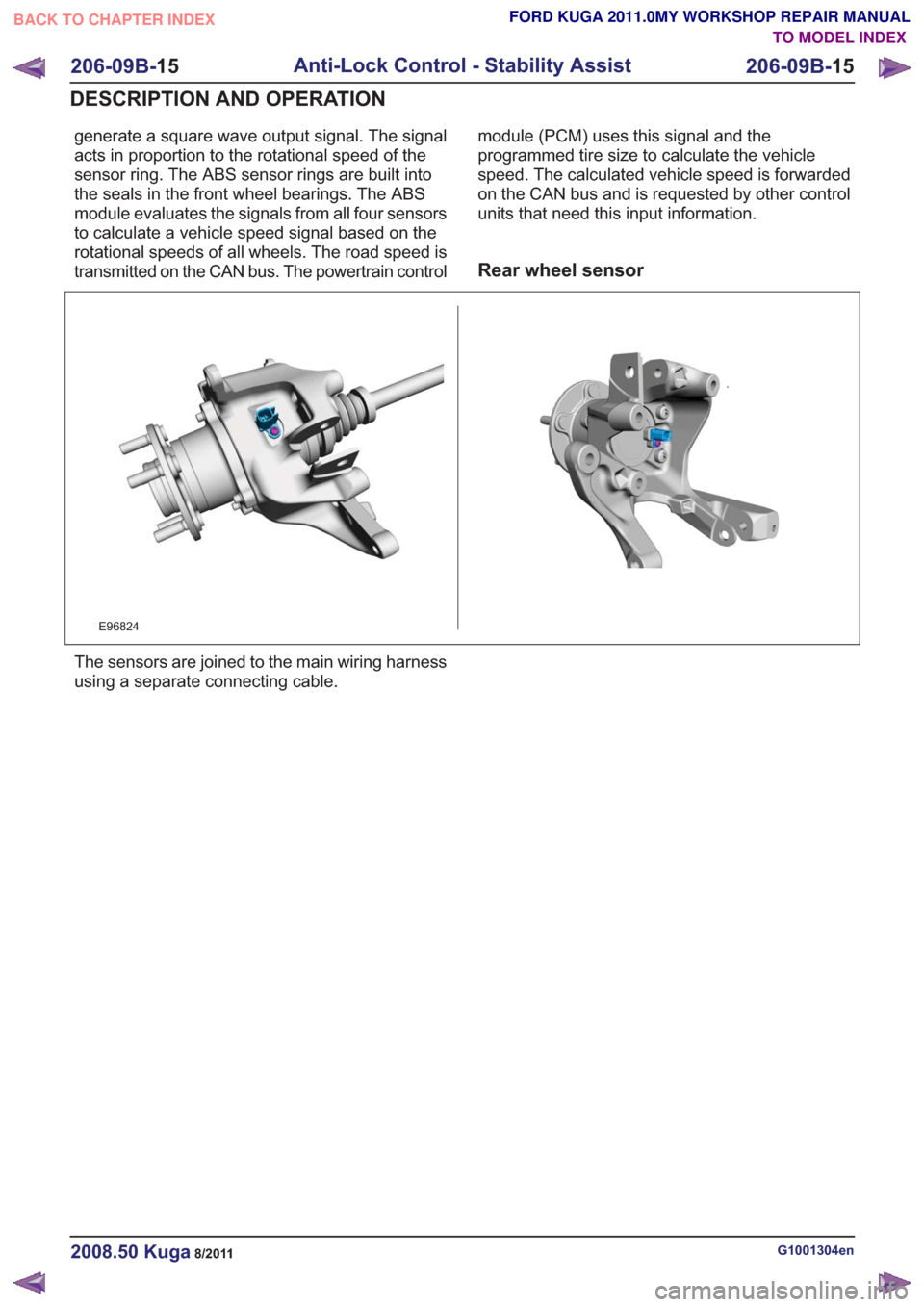
Rear wheel sensor
E96824
The sensors are joined to the main wiring harness
using a separate connecting cable.
G1001304en2008.50 Kuga8/2011
206-09B-
15
Anti-Lock Control - Stability Assist
206-09B- 15
DESCRIPTION AND OPERATION
TO MODEL INDEX
BACK TO CHAPTER INDEX
FORD KUGA 2011.0MY WORKSHOP REPAIR MANUAL