Page 1939 of 2057
E114520
16.
E114521
17.
E114522
18.General Equipment: Knife
E114515
19.Torque: 9Nm
E114514
G1163686en2008.50 Kuga8/2011
REMOVAL AND INSTALLATION
307-05- 9
Automatic Transmission/Transaxle External
Controls
— Vehicles With: 5-Speed Automatic Transaxle - AW55 AWD/6-Speed
Automatic Transaxle - 6DCT450
307-05-9
.
FORD KUGA 2011.0MY WORKSHOP REPAIR MANUAL
TO MODEL INDEX
BACK TO CHAPTER INDEX
50 mm
15. Torque: 9Nm
x4
Page 1940 of 2057
Installation
CAUTION: Gearshift cables must not be
kinked or bent.
1. To install, reverse the removal procedure.
2. Torque: 25
Nm1.
2. Torque: 25
Nm
3. Torque: 30Nm
4. Torque: 25Nm
4
x2
2x2
1
3
x2
4
x2
2x2
1
3
x2
E100960
Vehicles With: 5-Speed Automatic Transaxle
- AW55 AWD (307-05 Automatic
Transmission/Transaxle External Controls -
Vehicles With: 5-Speed Automatic Transaxle
- AW55 AWD/6-Speed Automatic Transaxle
- 6DCT450, General Procedures).
G1163686en2008.50 Kuga8/2011
REMOVAL AND INSTALLATION
TO MODEL INDEX
BACK TO CHAPTER INDEX
3.
Refer to: Selector Lever Cable Adjustment -
FORD KUGA 2011.0MY WORKSHOP REPAIR MANUAL
307-05-10
Automatic Transmission/Transaxle External
Controls
— Vehicles With: 5-Speed Automatic Transaxle - AW55 AWD/6-Speed
Automatic Transaxle - 6DCT450
307-05-10
.
Page 1941 of 2057
Selector Lever Assembly — Vehicles With: 5-Speed AutomaticTransaxle - AW55 AWD
Removal
CAUTION: Gearshift cables must not be
kinked or bent.
NOTE: Removal steps in this procedure may
contain installation details.
1. Refer to: Floor Console Extension - Vehicles
With: Center Armrest (501-12 Instrument
Panel and Console, Removal and Installation).
2.
E114518
3.
E114519
4.
x4x4
E101415
5. Torque: 9Nm
50 mm
x4
50 mm
x4
E114520
G1163687en2008.50 Kuga8/2011
REMOVAL AND INSTALLATION
TO MODEL INDEX
BACK TO CHAPTER INDEX
FORD KUGA 2011.0MY WORKSHOP REPAIR MANUAL
307-05-
11
Automatic Transmission/Transaxle External
Controls
— Vehicles With: 5-Speed Automatic Transaxle - AW55 AWD/6-Speed
Automatic Transaxle - 6DCT450
307-05-11
.
Page 1950 of 2057

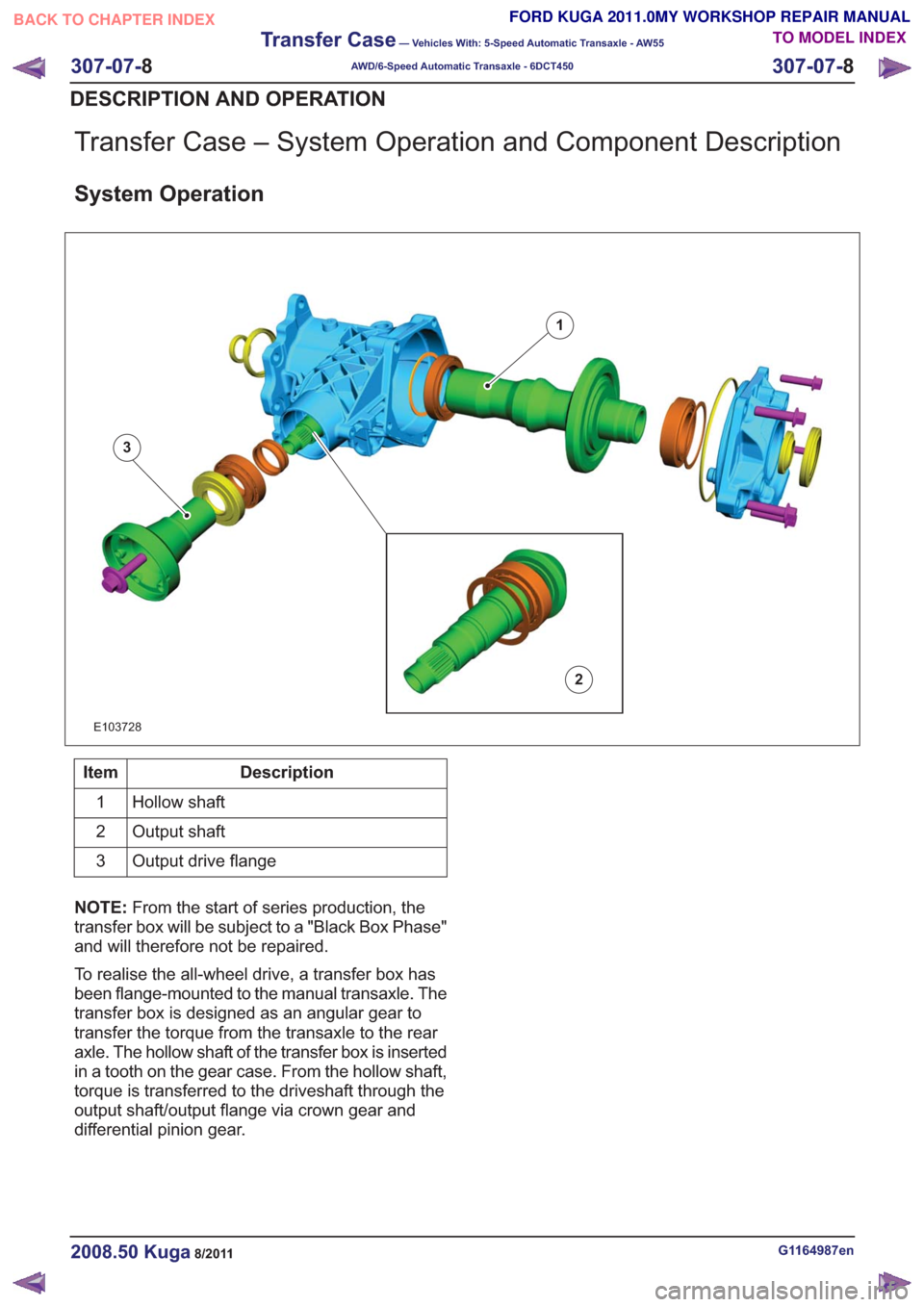
Transfer Case – System Operation and Component Description
System Operation
1
2
3
E103728
Description
Item
Hollow shaft
1
Output shaft
2
Output drive flange
3
NOTE: From the start of series production, the
transfer box will be subject to a "Black Box Phase"
and will therefore not be repaired.
To realise the all-wheel drive, a transfer box has
been flange-mounted to the manual transaxle. The
transfer box is designed as an angular gear to
transfer the torque from the transaxle to the rear
axle. The hollow shaft of the transfer box is inserted
in a tooth on the gear case. From the hollow shaft,
torque is transferred to the driveshaft through the
output shaft/output flange via crown gear and
differential pinion gear.
G1164987en2008.50 Kuga8/2011
307-07- 8
Transfer Case
— Vehicles With: 5-Speed Automatic Transaxle - AW55
AWD/6-Speed Automatic Transaxle - 6DCT450
307-07- 8
DESCRIPTION AND OPERATION
TO MODEL INDEX
BACK TO CHAPTER INDEX
FORD KUGA 2011.0MY WORKSHOP REPAIR MANUAL
Page 1951 of 2057
Transfer Case Fluid Level Check
MaterialsSpecification
Name
8U7J-19G518-BA
Rear Axle Oil SAE 75W-
90
Inspection
1. Refer to: Health and Safety Precautions (100-00
General Information, Description and
Operation).
2.
E139436
3. Material: Rear Axle Oil SAE 75W-90
(8U7J-19G518-BA) transmission fluid
•
• Correct the rear axle oil level if neccessary.
• 20ml~1mm
0mm0mm
E114595
4. NOTE:
Make sure that a new component is
installed.
Torque: 34
Nm
E139434
G1164988en2008.50 Kuga8/2011
307-07- 9
Transfer Case
— Vehicles With: 5-Speed Automatic Transaxle - AW55
AWD/6-Speed Automatic Transaxle - 6DCT450
307-07- 9
GENERAL PROCEDURES
TO MODEL INDEX
BACK TO CHAPTER INDEX
FORD KUGA 2011.0MY WORKSHOP REPAIR MANUAL
Page 1964 of 2057
Exhaust Flexible Pipe
General EquipmentCable TiesMaterials
Specification
Name
SA-M1C9107-A / YS5J-
M1C9107-AA
Grease KS-PS
Removal
NOTE:
Removal steps in this procedure may
contain installation details.
1.
E65070
2. CAUTION: Make sure that the inside of the pipe ends are clean and free of oil
residue.
1. Torque: 10Nm
2. Torque: 4Nm
3. Torque: 10Nm
2
1
3
E68504
3.Torque: 20Nm
E112607
1
2
34
4.
E67948
2
1
5. CAUTIONS:
Jointing compound must not be used
forward of the catalytic converter.
G1079152en2008.50 Kuga8/2011
309-00- 3
Exhaust System— 2.5L Duratec (147kW/200PS) - VI5309-00-
3
REMOVAL AND INSTALLATION
TO MODEL INDEX
BACK TO CHAPTER INDEX
FORD KUGA 2011.0MY WORKSHOP REPAIR MANUAL
Page 1965 of 2057
Make sure that the exhaust flexible pipe
is not forcibly bent.
2. Torque: 47
Nm
3. Torque: 28Nm
E112609
x3
1
2
3
6. Refer to: Lifting(100-02 Jacking and Lifting,
Description and Operation).
7.
E65299
8. General Equipment: Cable Ties
TIE0014991
9.
E66050
10.Torque: 30Nm
E112254
G1079152en2008.50 Kuga8/2011
309-00- 4
Exhaust System— 2.5L Duratec (147kW/200PS) - VI5309-00-
4
REMOVAL AND INSTALLATION
TO MODEL INDEX
BACK TO CHAPTER INDEX
FORD KUGA 2011.0MY WORKSHOP REPAIR MANUAL
Page 1966 of 2057
11. CAUTION: Make sure that the exhaustflexible pipe is not forcibly bent.
Torque: 48Nm
E112253
x2
12.Material: Grease KS-PS (SA-M1C9107-A /
YS5J-M1C9107-AA) grease
Torque: 48
Nm
E112608
Installation
1. To install, reverse the removal.
G1079152en2008.50 Kuga8/2011
309-00- 5
Exhaust System— 2.5L Duratec (147kW/200PS) - VI5309-00-
5
REMOVAL AND INSTALLATION
TO MODEL INDEX
BACK TO CHAPTER INDEX
FORD KUGA 2011.0MY WORKSHOP REPAIR MANUAL