Page 1845 of 2057
Description
Item
The TR sensor
3
The TSS sensor
4
The TFT sensor
5
TCM6Description
Item
OSS (output shaft speed) sensor
7
Solenoid valves in valve body
8
Clutches and brakes
9
TCC
10
The function is divided into an electronic and a
hydraulic control system.
Electronic Control System
Depending on the input signals, the TCM mounted
on the transmission actuates the solenoid valves
in the valve body. The TCM calculates and stores
adaptive data, fault codes and values for diagnosis.
The TR sensor is integrated in the TCM.
Hydraulic Control System
When the engine is running, a fluid pump integrated
in the transaxle housing generates the hydraulic pressure required for controlling the automatic
transaxle.
Through actuation of the solenoid valves, hydraulic
pressure is applied to the clutches and brakes via
hydraulic channels in the valve body and the
transaxle. The control valves regulate the hydraulic
pressure in accordance with the duty cycle of the
electrical PWM signal. The controlled hydraulic
pressure enables smooth shifting or the generation
of a defined slip through actuation of the relevant
clutches and brakes.
Solenoid valves are either in the 'open' or 'closed'
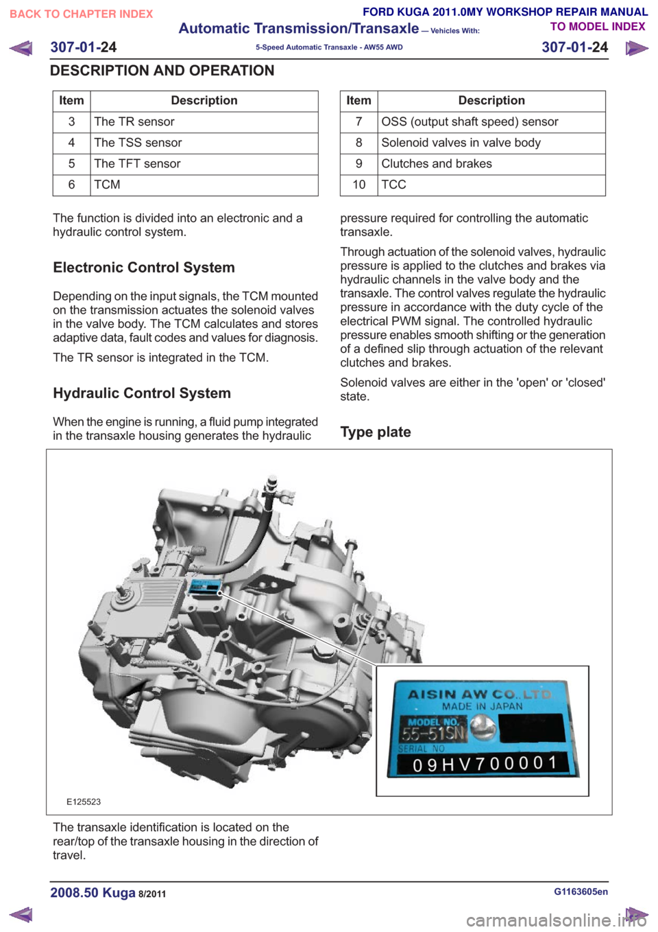
state.Type plate
E125523
The transaxle identification is located on the
rear/top of the transaxle housing in the direction of
travel.
G1163605en2008.50 Kuga8/2011
307-01-
24
Automatic Transmission/Transaxle
— Vehicles With:
5-Speed Automatic Transaxle - AW55 AWD
307-01- 24
DESCRIPTION AND OPERATION
TO MODEL INDEX
BACK TO CHAPTER INDEX
FORD KUGA 2011.0MY WORKSHOP REPAIR MANUAL
Page 1846 of 2057
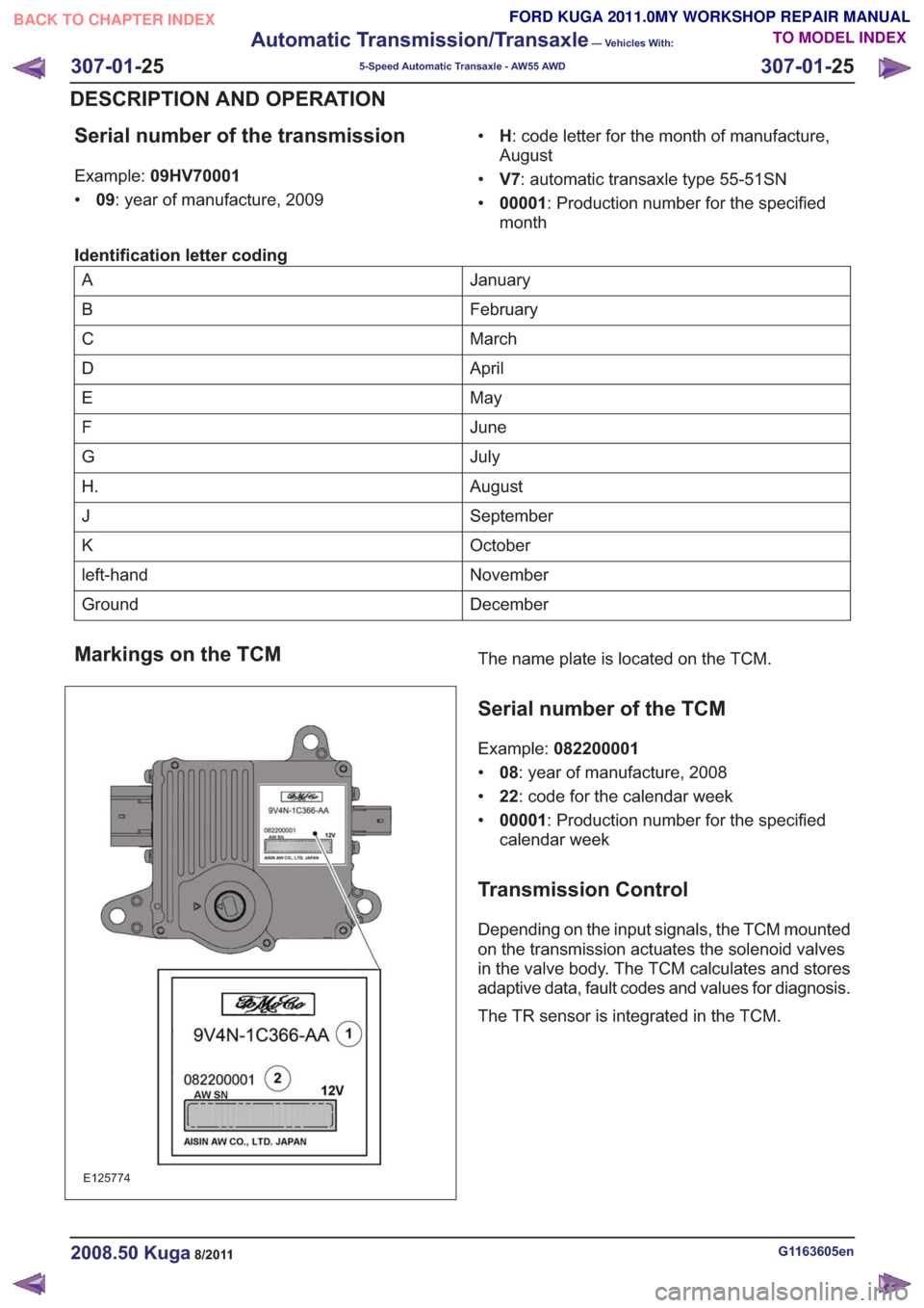
Serial number of the transmission
Example:09HV70001
• 09: year of manufacture, 2009 •
H: code letter for the month of manufacture,
August
• V7: automatic transaxle type 55-51SN
• 00001 : Production number for the specified
month
Identification letter coding
January
A
February
B
March
C
April
D
May
E
June
F
July
G
August
H.
September
J
October
K
November
left-hand
December
Ground
Markings on the TCM
E125774
The name plate is located on the TCM.
Serial number of the TCM
Example: 082200001
• 08: year of manufacture, 2008
• 22: code for the calendar week
• 00001 : Production number for the specified
calendar week
Transmission Control
Depending on the input signals, the TCM mounted
on the transmission actuates the solenoid valves
in the valve body. The TCM calculates and stores
adaptive data, fault codes and values for diagnosis.
The TR sensor is integrated in the TCM.
G1163605en2008.50 Kuga8/2011
307-01- 25
Automatic Transmission/Transaxle
— Vehicles With:
5-Speed Automatic Transaxle - AW55 AWD
307-01- 25
DESCRIPTION AND OPERATION
TO MODEL INDEX
BACK TO CHAPTER INDEX
FORD KUGA 2011.0MY WORKSHOP REPAIR MANUAL
Page 1873 of 2057
00.2 1.0 0.80.60.4
0
0.2 1.0
0.80.60.40
0.2 1.0 0.80.60.40
0.2 1.0 0.80.60.4
E125990
1
2
Description
Item
Hydraulic pressure
1
Average current (A)
2
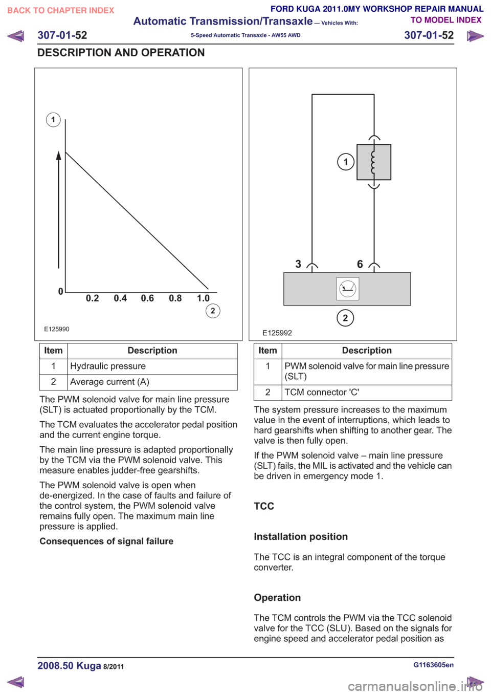
The PWM solenoid valve for main line pressure
(SLT) is actuated proportionally by the TCM.
The TCM evaluates the accelerator pedal position
and the current engine torque.
The main line pressure is adapted proportionally
by the TCM via the PWM solenoid valve. This
measure enables judder-free gearshifts.
The PWM solenoid valve is open when
de-energized. In the case of faults and failure of
the control system, the PWM solenoid valve
remains fully open. The maximum main line
pressure is applied.
Consequences of signal failure
E125992
2
1
Description
Item
PWM solenoid valve for main line pressure
(SLT)
1
TCM connector 'C'
2
The system pressure increases to the maximum
value in the event of interruptions, which leads to
hard gearshifts when shifting to another gear. The
valve is then fully open.
If the PWM solenoid valve – main line pressure
(SLT) fails, the MIL is activated and the vehicle can
be driven in emergency mode 1.
TCC
Installation position
The TCC is an integral component of the torque
converter.
Operation
The TCM controls the PWM via the TCC solenoid
valve for the TCC (SLU). Based on the signals for
engine speed and accelerator pedal position as
G1163605en2008.50 Kuga8/2011
307-01- 52
Automatic Transmission/Transaxle
— Vehicles With:
5-Speed Automatic Transaxle - AW55 AWD
307-01- 52
DESCRIPTION AND OPERATION
TO MODEL INDEX
BACK TO CHAPTER INDEX
FORD KUGA 2011.0MY WORKSHOP REPAIR MANUAL
Page 1876 of 2057
Description
Item
Drive
3
Intake side
4
Delivery side
5
The fluid pump operates on the principle of a
G-rotor fluid pump.
The fluid pump draws transmission fluid from the
fluid pan, builds up fluid pressure and then supplies
it to the valve body.
The fluid pump is driven by the crankshaft via the
torque converter housing.
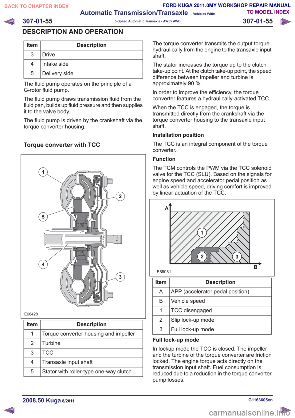
Torque converter with TCC
E66428E66428
1
2
3
5
4
Description
Item
Torque converter housing and impeller
1
Turbine
2
TCC3
Transaxle input shaft
4
Stator with roller-type one-way clutch
5 The torque converter transmits the output torque
hydraulically from the engine to the transaxle input
shaft.
The stator increases the torque up to the clutch
take-up point. At the clutch take-up point, the speed
difference between impeller and turbine is
approximately 90 %.
In order to improve the efficiency, the torque
converter features a hydraulically-activated TCC.
When the TCC is engaged, the torque is
transmitted directly from the crankshaft via the
torque converter housing to the transaxle input
shaft.
Installation position
The TCC is an integral component of the torque
converter.
Function
The TCM controls the PWM via the TCC solenoid
valve for the TCC (SLU). Based on the signals for
engine speed and accelerator pedal position as
well as vehicle speed, driving comfort is improved
by linear actuation of the TCC.
E89081
1
A
B
23
Description
Item
APP (accelerator pedal position)
A
Vehicle speed
B
TCC disengaged
1
Slip lock-up mode
2
Full lock-up mode
3
Full lock-up mode
In lockup mode the TCC is closed. The impeller
and the turbine of the torque converter are friction
locked. The engine torque acts directly on the
transmission input shaft. Fuel consumption is
reduced due to a reduction in the torque converter
pump losses.
G1163605en2008.50 Kuga8/2011
307-01- 55
Automatic Transmission/Transaxle
— Vehicles With:
5-Speed Automatic Transaxle - AW55 AWD
307-01- 55
DESCRIPTION AND OPERATION
TO MODEL INDEX
BACK TO CHAPTER INDEX
FORD KUGA 2011.0MY WORKSHOP REPAIR MANUAL
Page 1879 of 2057
transaxle output shaft. The frequency of the
square-wave signal increases with the speed of
the transmission output shaft.
The OSS sensor picks up the speed at the gear of
the parking lock.
The TCM uses the information from the OSS
sensor for the following parameters:
• Calculation of the degree of torque reductionthat needs to be requested by the PCM during
shifting.
• Calculation of the shift points.
• Calculation of the engaging and disengaging point for the TCC (lock-up function).
• Calculation of the current gear ratios by comparison of the TSS sensor signal.
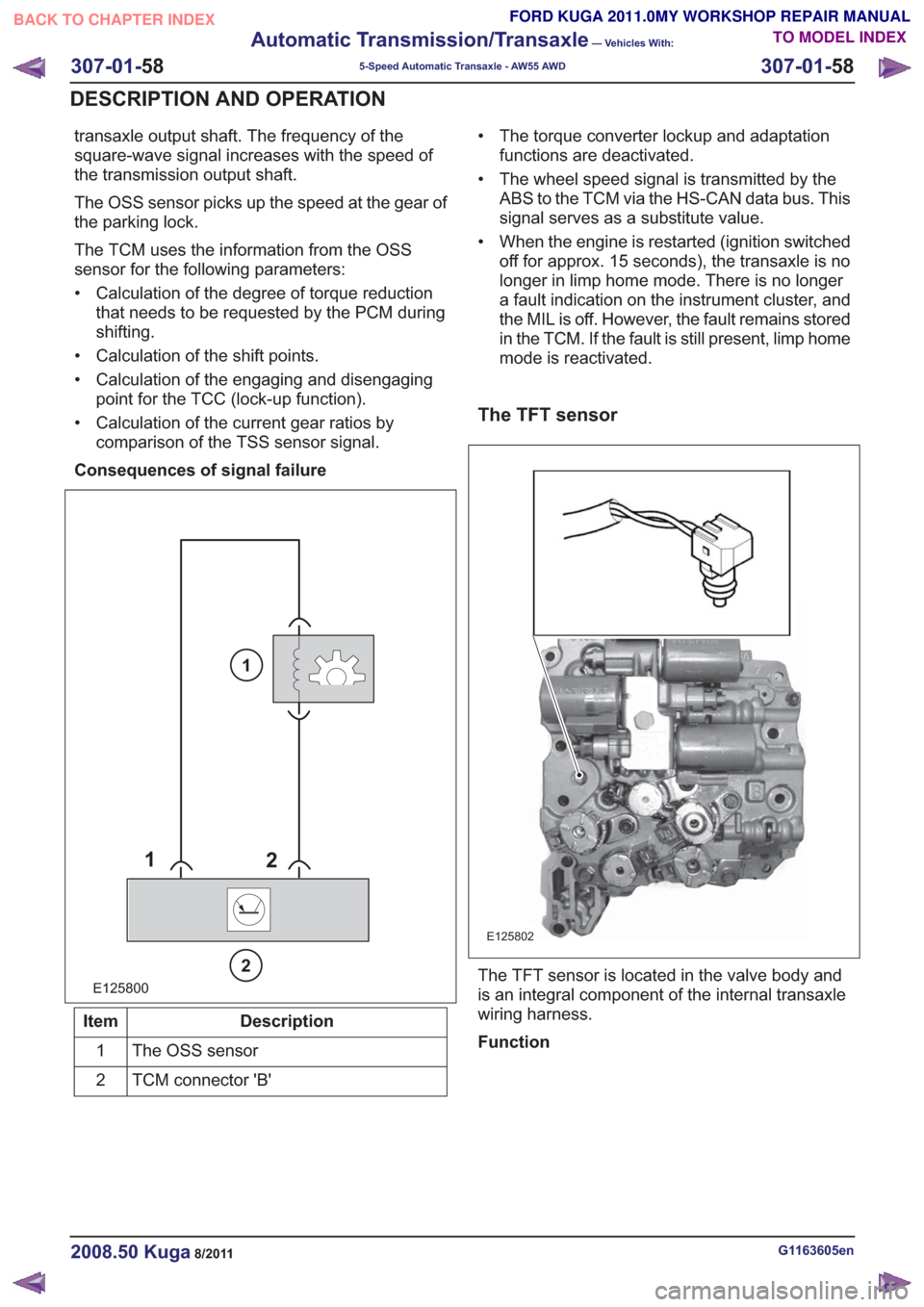
Consequences of signal failure
E125800
1 2
2
1
Description
Item
The OSS sensor
1
TCM connector 'B'
2 • The torque converter lockup and adaptation
functions are deactivated.
• The wheel speed signal is transmitted by the ABS to the TCM via the HS-CAN data bus. This
signal serves as a substitute value.
• When the engine is restarted (ignition switched off for approx. 15 seconds), the transaxle is no
longer in limp home mode. There is no longer
a fault indication on the instrument cluster, and
the MIL is off. However, the fault remains stored
in the TCM. If the fault is still present, limp home
mode is reactivated.
The TFT sensor
E125802
The TFT sensor is located in the valve body and
is an integral component of the internal transaxle
wiring harness.
Function
G1163605en2008.50 Kuga8/2011
307-01- 58
Automatic Transmission/Transaxle
— Vehicles With:
5-Speed Automatic Transaxle - AW55 AWD
307-01- 58
DESCRIPTION AND OPERATION
TO MODEL INDEX
BACK TO CHAPTER INDEX
FORD KUGA 2011.0MY WORKSHOP REPAIR MANUAL
Page:
< prev 1-8 9-16 17-24