2011 FORD KUGA Gas
[x] Cancel search: GasPage 73 of 2057

Personal protection
Besides the body and limbs, several organs vital
to life are in very particular danger. Because
damage is mostly irreparable, special attention and
comprehensive protection is necessary.
Protective equipment
Always use the appropriate protective equipment:
• Protective helmet or welding mask
• Breathing protection
• Protective clothes gloves and safety boots
• Ear defenders
• Extraction systems
Always carry out an operational check on your
protective equipment every time before you start
working!
Breathing protection
WARNING: Vapor or spray mist containing
isocyanates as a paint base or hardener
can cause toxic respiratory disease
(conditions similar to asthma) leading to
permanent damage, even when inhaled in
the lowest concentrations
The instructions for use provided by the
manufacturer must be observed when working with
breathing protection equipment.
During painting work and in the preparations for
painting, gases, vapors, mists or dusts can appear
in dangerous concentrations.
Breathing protection devices which are
independent of the local atmosphere are most
suitable.
In these types of isolation systems, a compressed
air hose carries natural air from the compressor
line into the protective mask. During supply, the
air undergoes pressure reduction, water removal,
fine filtration and usually warming to natural breath
temperature.
E59518
Description
Item
Protective hood with fresh air supply
1
Protective clothing
2
Protective gloves
3
Protective footwear
4
Only for short periods of work or minimal
concentrations of hazardous substances breathing
protection devices with a combination filter is
suitable as breathing protection equipment.
G963390en2008.50 Kuga8/2011
100-00- 68
General Information
100-00- 68
DESCRIPTION AND OPERATION
TO MODEL INDEX
BACK TO CHAPTER INDEX
FORD KUGA 2011.0MY WORKSHOP REPAIR MANUAL
Page 168 of 2057

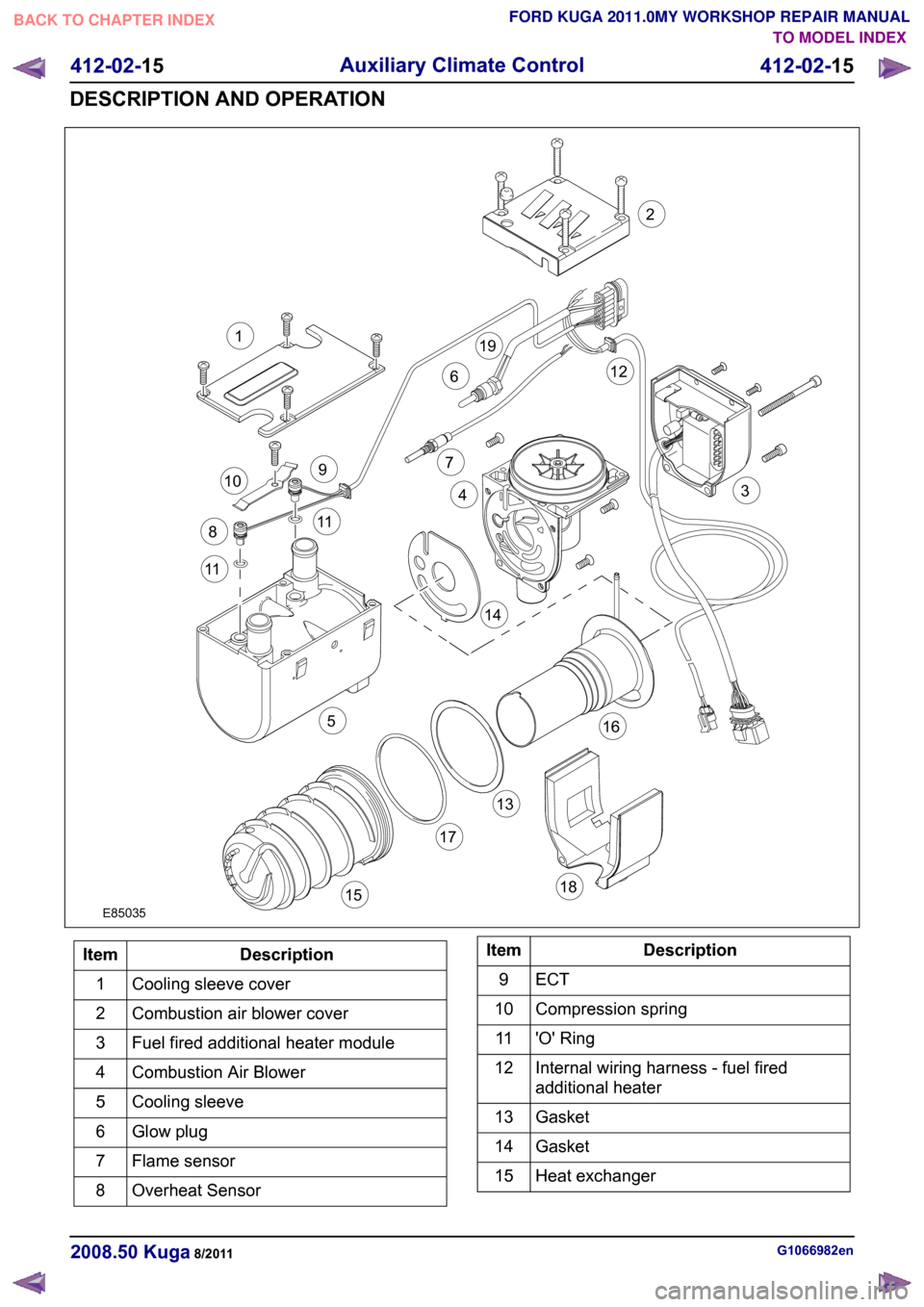
Description
Item
Cooling sleeve cover
1
Combustion air blower cover
2
Fuel fired additional heater module
3
Combustion Air Blower
4
Cooling sleeve
5
Glow plug
6
Flame sensor
7
Overheat Sensor
8 Description
Item
ECT9
Compression spring
10
'O' Ring
11
Internal wiring harness - fuel fired
additional heater
12
Gasket
13
Gasket
14
Heat exchanger
15 G1066982en
2008.50 Kuga 8/2011 412-02-15
Auxiliary Climate Control
412-02-15
DESCRIPTION AND OPERATIONTO MODEL INDEX
BACK TO CHAPTER INDEX
FORD KUGA 2011.0MY WORKSHOP REPAIR MANUALE850351132126791011115144316171518198
Page 263 of 2057

Charging System
Refer to Wiring Diagrams Section 414-02, for
schematic and connector information.
General Equipment
Midtronics EXP-1050 battery tester
Midtronics GR590-2
Ford diagnostic equipment
Inspection and Verification
WARNINGS: Batteries contain sulphuric acid. Avoid
contact with skin, eyes, or clothing. Also,
shield your eyes when working near
batteries to protect against possible
splashing of the acid solution. In case of
acid contact with skin or eyes, flush
immediately with water for a minimum of
15 minutes and get prompt medical
attention. If acid is swallowed, call a
physician immediately. Failure to follow
these instructions may result in personal
injury.
Batteries normally produce explosive
gases which can cause personal injury.
Therefore, do not allow flames, sparks or
lighted substances to come near the
battery. When charging or working near a
battery, always shield your face and
protect your eyes. Always provide
ventilation. Failure to follow these
instructions may result in personal injury.
1. Verify the customer concern.
2. Visually inspect for obvious signs of mechanical
or electrical damage.
Visual Inspection Chart Electrical
Mechanical
– Fuse(s)
– Wiring harness(es)
– Generator
– Electricalconnector(s)
– Battery junction box (BJB)
– Battery
– Battery cables
– Battery monitoring sensor (BMS)
– Charging system warning indicator
–
Accessory drive belt
– Generator
3. If an obvious cause for an observed or reported concern is found, correct the cause (if possible)
before proceeding to the next step.
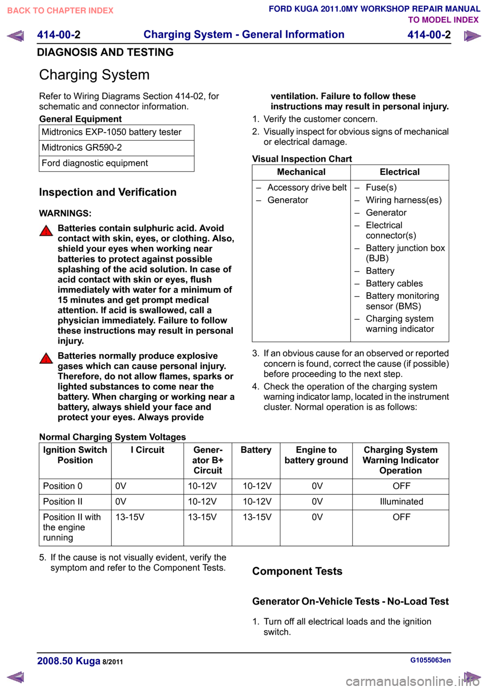
4. Check the operation of the charging system warning indicator lamp, located in the instrument
cluster. Normal operation is as follows:
Normal Charging System Voltages Charging System
Warning Indicator Operation
Engine to
battery ground
Battery
Gener-
ator B+ Circuit
I Circuit
Ignition Switch
Position
OFF
0V
10-12V
10-12V
0V
Position 0
Illuminated
0V
10-12V
10-12V
0V
Position II
OFF
0V
13-15V
13-15V
13-15V
Position II with
the engine
running
5. If the cause is not visually evident, verify the symptom and refer to the Component Tests. Component Tests
Generator On-Vehicle Tests - No-Load Test
1. Turn off all electrical loads and the ignition
switch. G1055063en
2008.50 Kuga 8/2011 414-00-2
Charging System - General Information
414-00-2
DIAGNOSIS AND TESTINGTO MODEL INDEX
BACK TO CHAPTER INDEX
FORD KUGA 2011.0MY WORKSHOP REPAIR MANUAL
Page 270 of 2057

Battery Disconnect and Connect
Disconnect
WARNINGS:
Batteries normally produce explosive
gases which may cause personal injury,
therefore do not allow flames, sparks or
lighted substances to come near the
battery. When charging or working near
the battery always shield your face and
protect your eyes. Always provide
adequate ventilation. Failure to follow
these instructions may result in personal
injury.
The supplemental restraint system (SRS)
is active for a certain length of time after
the power supply has been disconnected.
Wait for a minimum of 3 minutes before
disconnecting or removing any SRS
components.
Audio unit key code saving devices must
not be used when working on
supplemental restraint or fuel systems.
When using these devices the vehicle
electrical system is still live but with a
reduced current flow. Failure to follow this
instruction may result in personal injury.
CAUTION: Make sure the engine is not
running before disconnecting the battery
ground cable to avoid damage to the
vehicle electrical system.
NOTE: Disconnecting the battery will erase fault
codes, drive values and customer data stored in
the modules.
NOTE: This procedure should be used to
disconnect the battery while carrying out repairs
that refer to the battery being disconnected.
1. Refer to: Battery and Battery Charging Health
and Safety Precautions (100-00 General
Information, Description and Operation).
2. Obtain and record the audio unit keycode and
preset radio frequencies. 3.
G1062389en
2008.50 Kuga 8/2011 414-01-2
Battery, Mounting and Cables
414-01-2
GENERAL PROCEDURESTO MODEL INDEX
BACK TO CHAPTER INDEX
FORD KUGA 2011.0MY WORKSHOP REPAIR MANUALE103137
Page 340 of 2057

The turn signal lamps and side lights are the same as in conventional headlamps.
Bulb color
Current draw
Bulb
Lamp
Clear
35W
D1S
Low-beams
Clear
55W
H1
High beam headlamp
Clear
21W
H21W
Turn signal indicator
Clear
5W
W5W
Side lamp
Headlamp levelling
Vehicles with conventional headlamps are
equipped with a manual headlamp leveling system. An automatic headlamp leveling system is a legal
requirement for vehicles with gas discharge
headlamps.
The automatic headlamp levelling system is a
dynamic system which provides additional benefits
for the driver in terms of improved illumination of
the road due to improved control over the
headlamp beam.
In a static system, the vehicle is only considered
as a stationary object, whereas a dynamic system
also takes into account the dynamic changes to
the inclination of the vehicle whilst driving.
In order to prevent unnecessary changes in the
height of the headlamp beam, the system filters
out surface irregularities and any pitching of the
vehicle under braking and acceleration.
The system is designed to respond to changes in
the inclination of the vehicle caused by load
changes or long-term effects of aerodynamic forces
acting on the vehicle (e.g. due to continuous driving
at high speeds).
Accordingly, the system needs to be set up with
the aid of WDS (Worldwide Diagnostic System)
after any components are replaced or any other
repairs are carried out.
G1079626en
2008.50 Kuga 8/2011 417-01-6
Exterior Lighting
417-01-6
DESCRIPTION AND OPERATIONTO MODEL INDEX
BACK TO CHAPTER INDEX
FORD KUGA 2011.0MY WORKSHOP REPAIR MANUALE101614
Page 344 of 2057

Description
Item
Headlamp units with turn signal lamp, side
lamp, dipped beam headlamp, main beam
headlamp, positioning motor for headlamp
leveling system
8
External mirror with side turn signal lamps
and door entry lamp
9
Door locking units for the front doors
10
Fog lamp
11
Rear fog lights
12
Gas discharge headlamp control module
13 Description
Item
GEM14
Vehicle level sensors
15
Lighting switch
16
Multifunction lever
17
Hazard flasher switch
18
Combined rain sensor/light sensor
19
Reverse gear switch
20
Keyless Vehicle Module
21
System Operation
Headlamp levelling
Xenon headlamp
The following components are part of the automatic
headlamp leveling system:
• Vehicle level sensors on the front and rear axles
• Control module
• Actuator motors for headlamp leveling Accordingly, the system needs to be set up with
the aid of WDS after any components are replaced
or any other repairs are carried out.
The front and rear sensors are Hall sensors which
send a digital signal to the control unit.
Conventional HeadlampsDescription
Item
Light switch with manual headlamp
leveling system
1
Headlamp units with positioning motors
for headlamp leveling system
2 G1079627en
2008.50 Kuga 8/2011 417-01-10
Exterior Lighting
417-01-10
DESCRIPTION AND OPERATIONTO MODEL INDEX
BACK TO CHAPTER INDEX
FORD KUGA 2011.0MY WORKSHOP REPAIR MANUALE10260312
Page 347 of 2057

g.
Heated rear window
h. Heater blower motor
i. Headlamp washer system (vehicles with gas discharge headlamps)
j. Electric booster heater (if fitted)
k. Autolamps (if fitted)
l. Alarm horn (vehicles with alarm system)
m. Rear window wiper
n. Rear heated window relay
When the heated rear window switch is pressed
again, the test of the relevant signal is terminated.
When the heated rear window switch is pressed
once more, the test for the next signal in the list is
started.
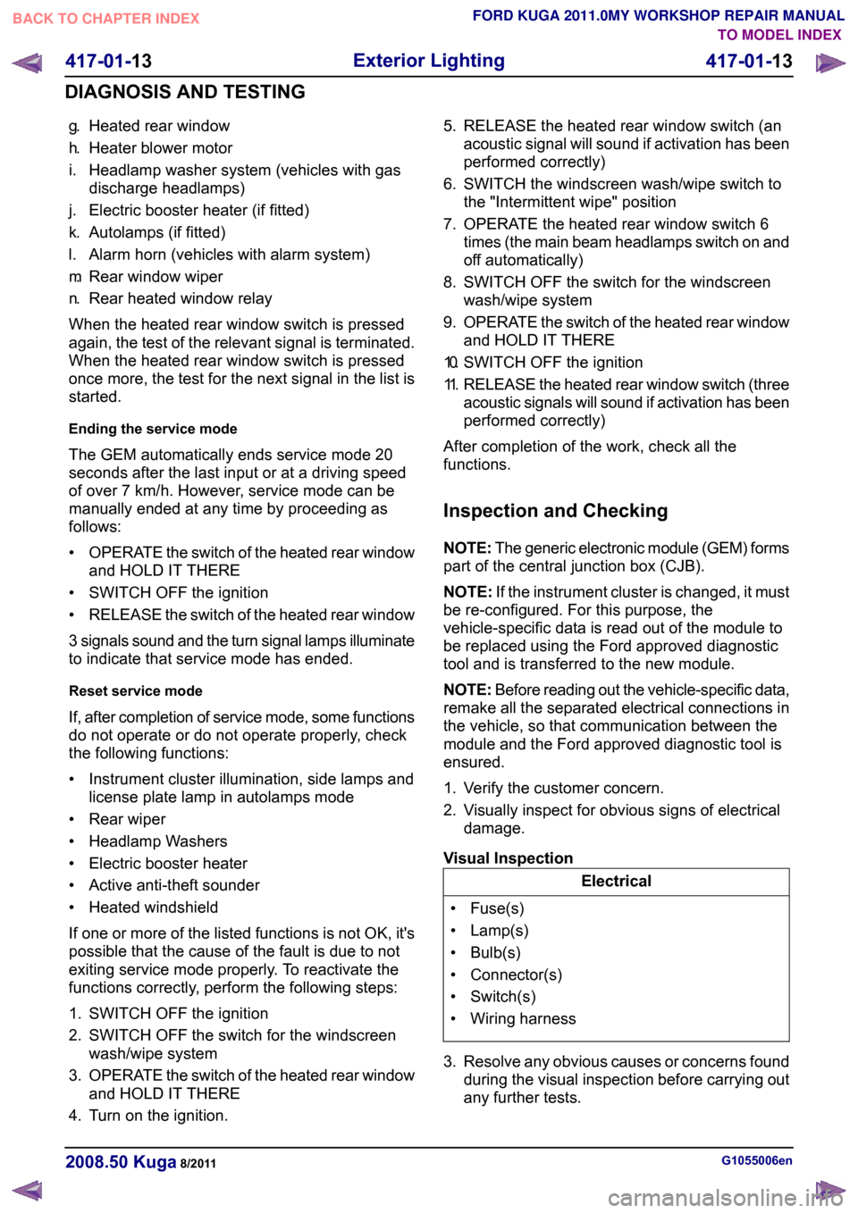
Ending the service mode
The GEM automatically ends service mode 20
seconds after the last input or at a driving speed
of over 7 km/h. However, service mode can be
manually ended at any time by proceeding as
follows:
• OPERATE the switch of the heated rear window
and HOLD IT THERE
• SWITCH OFF the ignition
• RELEASE the switch of the heated rear window
3 signals sound and the turn signal lamps illuminate
to indicate that service mode has ended.
Reset service mode
If, after completion of service mode, some functions
do not operate or do not operate properly, check
the following functions:
• Instrument cluster illumination, side lamps and license plate lamp in autolamps mode
• Rear wiper
• Headlamp Washers
• Electric booster heater
• Active anti-theft sounder
• Heated windshield
If one or more of the listed functions is not OK, it's
possible that the cause of the fault is due to not
exiting service mode properly. To reactivate the
functions correctly, perform the following steps:
1. SWITCH OFF the ignition
2. SWITCH OFF the switch for the windscreen wash/wipe system
3. OPERATE the switch of the heated rear window
and HOLD IT THERE
4. Turn on the ignition. 5. RELEASE the heated rear window switch (an
acoustic signal will sound if activation has been
performed correctly)
6. SWITCH the windscreen wash/wipe switch to the "Intermittent wipe" position
7. OPERATE the heated rear window switch 6 times (the main beam headlamps switch on and
off automatically)
8. SWITCH OFF the switch for the windscreen wash/wipe system
9. OPERATE the switch of the heated rear window
and HOLD IT THERE
10. SWITCH OFF the ignition
11. RELEASE the heated rear window switch (three
acoustic signals will sound if activation has been
performed correctly)
After completion of the work, check all the
functions.
Inspection and Checking
NOTE: The generic electronic module (GEM) forms
part of the central junction box (CJB).
NOTE: If the instrument cluster is changed, it must
be re-configured. For this purpose, the
vehicle-specific data is read out of the module to
be replaced using the Ford approved diagnostic
tool and is transferred to the new module.
NOTE: Before reading out the vehicle-specific data,
remake all the separated electrical connections in
the vehicle, so that communication between the
module and the Ford approved diagnostic tool is
ensured.
1. Verify the customer concern.
2. Visually inspect for obvious signs of electrical damage.
Visual Inspection Electrical
• Fuse(s)
• Lamp(s)
• Bulb(s)
• Connector(s)
• Switch(s)
• Wiring harness
3. Resolve any obvious causes or concerns found during the visual inspection before carrying out
any further tests. G1055006en
2008.50 Kuga 8/2011 417-01-13
Exterior Lighting
417-01-13
DIAGNOSIS AND TESTINGTO MODEL INDEX
BACK TO CHAPTER INDEX
FORD KUGA 2011.0MY WORKSHOP REPAIR MANUAL
Page 349 of 2057

Headlamps
Refer to
Wiring Diagrams Section 417-1, for
schematic and connector information.
Description of operation
A diagnosis of the generic electronic module (GEM)
can be performed with the Ford approved
diagnostic tool. Furthermore, an integrated service
mode enables testing of the input and output
signals without the need for further tools. To enable
activation of service mode:
• switch off the ignition,
• switch off all other electrical consumers,
• apply the handbrake,
• shift to neutral
• and close the doors.
Activating the service mode
Proceed as follows to activate the service mode:
• OPERATE the switch of the heated rear window
and HOLD IT THERE
• Turn on the ignition.
• RELEASE the switch of the heated rear window
A signal sounds and the turn signal lamps come
on to indicate that service mode has been
successfully activated.
NOTE: If the alarm is activated (in vehicles fitted
with an anti-theft alarm system), service mode
cannot be activated.
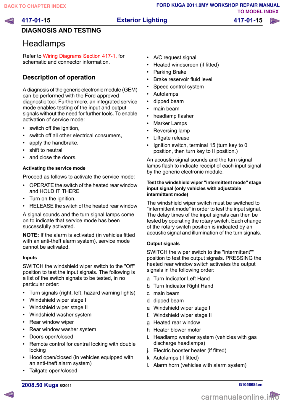
Inputs
SWITCH the windshield wiper switch to the "Off"
position to test the input signals. The following is
a list of the switch signals to be tested, in no
particular order:
• Turn signals (right, left, hazard warning lights)
• Windshield wiper stage I
• Windshield wiper stage II
• Windshield washer system
• Rear window wiper
• Rear window washer system
• Doors open/closed
• Remote control for central locking with double locking
• Hood open/closed (in vehicles equipped with an anti-theft alarm system)
• Tailgate open/closed • A/C request signal
• Heated windscreen (if fitted)
• Parking Brake
• Brake reservoir fluid level
• Speed control system
• Autolamps
• dipped beam
• main beam
• headlamp flasher
• Marker Lamps
• Reversing lamp
• Liftgate release
• Ignition switch, terminal 15 (turn key to 0
position, then turn key to II position.)
An acoustic signal sounds and the turn signal
lamps flash to indicate receipt of each input signal
by the generic electronic module.
Test the windshield wiper "intermittent mode" stage
input signal (only vehicles with adjustable
intermittent mode)
The windshield wiper switch must be switched to
"intermittent mode" in order to test the input signal.
The delay times of the input signals can then be
tested by operating the rotary switch. Each change
of the rotary switch position is indicated by an
acoustic signal and illumination of the turn signals.
Output signals
SWITCH the wiper switch to the "intermittent""
position to test the output signals. PRESSING the
heated rear window switch activates the output
signals in the following order:
a. Turn Indicator Left Hand
b. Turn Indicator Right Hand
c. main beam
d. dipped beam
e. Windshield wiper stage I
f. Windshield wiper stage II
g. Heated rear window
h. Heater blower motor
i. Headlamp washer system (vehicles with gas discharge headlamps)
j. Electric booster heater (if fitted)
k. Autolamps (if fitted)
l. Alarm horn (vehicles with alarm system) G1056684en
2008.50 Kuga 8/2011 417-01-15
Exterior Lighting
417-01-15
DIAGNOSIS AND TESTINGTO MODEL INDEX
BACK TO CHAPTER INDEX
FORD KUGA 2011.0MY WORKSHOP REPAIR MANUAL