2011 FORD KUGA DTC code
[x] Cancel search: DTC codePage 200 of 2057

SECTION 413-13 Parking Aid
VEHICLE APPLICATION:
2008.50 Kuga
PAGE
CONTENTS
DESCRIPTION AND OPERATION
413-13-2
Parking Aid (Component Location).....................................................................................
413-13-5
Parking Aid (Overview).......................................................................................................
413-13-5
Parking aid sensors............................................................................................................
413-13-5
Front sensors detection range............................................................................................
413-13-6
Rear sensors detection range............................................................................................
413-13-6
Parking aid camera module................................................................................................
413-13-6
Parking Aid Camera...........................................................................................................
413-13-7
Parking Aid (System Operation and Component Description)...........................................
413-13-7
System Diagram.................................................................................................................
413-13-12
System Operation...............................................................................................................
413-13-12
Parking Aid......................................................................................................................
413-13-13
Parking Aid Camera........................................................................................................
413-13-15
Component Description......................................................................................................413-13-15Rear parking aid speaker................................................................................................
413-13-15Parking aid sensors........................................................................................................
413-13-15Parking aid module.........................................................................................................
413-13-16Front parking aid speaker...............................................................................................
413-13-16Parking aid switch...........................................................................................................
413-13-16Parking aid camera module............................................................................................
413-13-16Parking Aid Camera........................................................................................................
DIAGNOSIS AND TESTING 413-13-17
Parking Aid — Vehicles With: Front Parking Aid................................................................
413-13-17
Principles of Operation.......................................................................................................
413-13-17
Inspection and Verification..................................................................................................
413-13-17
Diagnostic Trouble Codes (DTC) Index..............................................................................
413-13-21
Symptom Chart...................................................................................................................
413-13-21
Pinpoint Tests.....................................................................................................................
413-13-29
Parking Aid — Vehicles With: Rear Parking Aid.................................................................
413-13-29
Principles of Operation.......................................................................................................
413-13-29
Inspection and Verification..................................................................................................
413-13-29
Diagnostic Trouble Codes (DTC) Index..............................................................................
413-13-32
Symptom Chart...................................................................................................................
413-13-32
Pinpoint Tests.....................................................................................................................
REMOVAL AND INSTALLATION 413-13-44
Parking Aid Module.............................................................................................................
413-13-45
Parking Aid Camera Module...............................................................................................
413-13-46
Parking Aid Camera............................................................................................................
413-13-48
Front Parking Aid Speaker.................................................................................................
413-13-49
Rear Parking Aid Speaker..................................................................................................
413-13-50
Front Parking Aid Sensor....................................................................................................
413-13-56
Rear Parking Aid Sensor.................................................................................................... 413-13-1
Parking Aid
413-13-1
.
TO MODEL INDEX
BACK TO CHAPTER INDEX
FORD KUGA 2011.0MY WORKSHOP REPAIR MANUAL
Page 214 of 2057

Component Description
Rear parking aid speaker
The rear parking aid speaker, in addition to its
actual function, is also used for audible indication
of various types of error in the front and rear
parking aids. If the rear parking aid speaker
becomes defective, the front parking aid speaker
will then be used to indicate failure modes.
If an error is detected in the system, a signal tone
is emitted via the speaker for 3 seconds.
Parking aid sensors
CAUTIONS:
Always keep sensors free from dirt, ice and
snow. Do not use any sharp objects to
clean the sensors.
If a high-pressure cleaner is used to wash
the vehicle, the jet must only be aimed at
the sensors briefly at a distance of at least
20 cm.
The parking aid sensor consists of the following:
• Plastic housing
• Aluminum membrane with Piezo disc
• Decoupling ring
• Printed circuit board (PCB)
The parking aid sensor consists of a sensor and a
holder. The holder makes sure that each parking
aid sensor is correctly orientated in relation to its
location in the rear bumper.
The sensors have a 3-pin connector which is
connected to the wiring harness of the front
bumper. This in turn is connected to the main body
wiring harness. Three pins provide for power
supply, ground and signal lines to and from the
parking aid module. The disc resonates at a frequency of ca. 50kHz,
producing the ultrasonic output. The disc also
receives the reflected echo signal from any objects
within range.
Parking aid module
The parking aid module has three connectors which
provide for power, ground and MS CAN bus
connections, as well as the front and rear parking
aid sensors, the parking aid switch and parking aid
speaker.
The parking aid module carries out self-check
routines and when the parking aid is active, checks
the parking aid sensor wiring for short or open
circuits. If a concern is detected, a diagnostic
trouble code (DTC) is stored in a memory in the
parking aid module and the front and rear parking
aid sensors will be disabled until the DTC is cleared
and the ignition cycled. The driver recognizes a
problem through the flashing LED and a shrill
continuous tone, which is emitted for 3 seconds
when the parking aid is activated. If the parking aid
is working properly, short tones are emitted instead
of this continuous tone. DTCs can be read using
the Ford approved diagnostic tool through the data
link connector (DLC).
G1034399en
2008.50 Kuga 8/2011 413-13-15
Parking Aid
413-13-15
DESCRIPTION AND OPERATIONTO MODEL INDEX
BACK TO CHAPTER INDEX
FORD KUGA 2011.0MY WORKSHOP REPAIR MANUALE89773 E89772
Page 216 of 2057

Parking Aid — Vehicles With: Front Parking Aid
Refer to Wiring Diagrams Section 413-13, for
schematic and connector information.
General Equipment
Ford diagnostic equipment
Principles of Operation
The ultrasonic parking aid system activates when
the ignition switch is turned to the RUN and when
the parking brake is OFF. If a front parking aid
switch is fitted the system will be de-activated and
a light emitting diode (LED) will indicate the state
of the system. A lit LED will indicate that the system
is currently deactivated. The parking aid system
will be disabled if a fault is detected in one of the
four front parking aid sensors, the parking aid
speaker or the parking aid module. An error tone
approximately 3 seconds long will be emitted from
the rear parking aid speaker if a fault is detected.
If the rear parking aid speaker is inoperative the
error tone will sound from the front parking aid
speaker.
Inspection and Verification
1. Verify the customer concern. 2. Visually inspect for obvious signs of electrical
damage.
Visual Inspection Chart Electrical
– Fuse(s)
– Wiring harness(s)
– Electrical connector(s)
– Battery junction box (BJB)
– Front parking aid sensor(s)
– Front parking aid speaker
– Parking aid module
3. If an obvious cause for an observed or reported concern is found, correct the cause (if possible)
before proceeding to the next step
4. If the cause is not visually evident, connect the Ford diagnostic equipment to the data link
connector (DLC) and select the vehicle system
to be tested from the diagnostic menu.
5. Retrieve the Diagnostic Trouble Code (DTC)s and refer to the DTC Index.
6. If no DTCs are retrieved or there is no communication with the module, proceed to the
Symptom Chart to continue diagnostics.
Diagnostic Trouble Codes (DTC) Index
DTC Index Action
Possible Source
Description
DTC
Check the circuit 8-GN9
(WH/GN) for short to battery.
IF the circuit is OK, INSTALL
a new parking aid module.
REFER to:Parking Aid
Module (413-13 Parking
Aid, Removal and Installa-
tion).
TEST the system for normal
operation.
• Parking aid sensor signal
circuit.
• Parking aid module.
Front outer left sensor signal
circuit short to battery
C1711
GO toPinpoint Test C.
• Parking aid sensor signal
circuit.
• Parking aid sensor.
• Parking aid module.
Front outer left sensor signal
circuit open or short to
ground
C1712 G325369en
2008.50 Kuga 8/2011 413-13-17
Parking Aid
413-13-17
DIAGNOSIS AND TESTINGTO MODEL INDEX
BACK TO CHAPTER INDEX
FORD KUGA 2011.0MY WORKSHOP REPAIR MANUAL
Page 228 of 2057

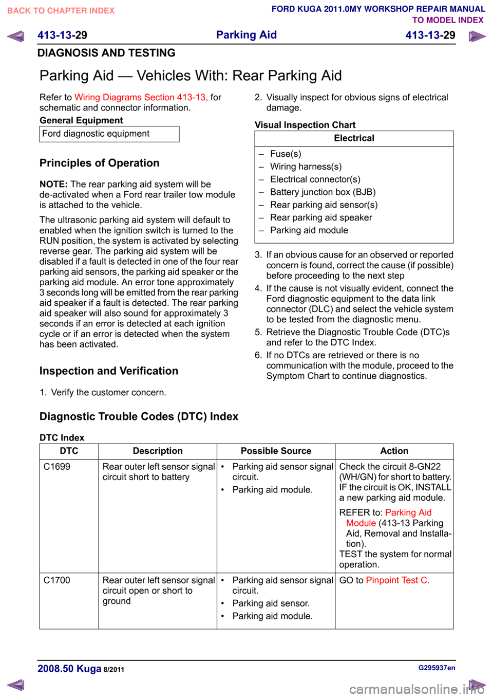
Parking Aid — Vehicles With: Rear Parking Aid
Refer to
Wiring Diagrams Section 413-13, for
schematic and connector information. General Equipment
Ford diagnostic equipment
Principles of Operation
NOTE: The rear parking aid system will be
de-activated when a Ford rear trailer tow module
is attached to the vehicle.
The ultrasonic parking aid system will default to
enabled when the ignition switch is turned to the
RUN position, the system is activated by selecting
reverse gear. The parking aid system will be
disabled if a fault is detected in one of the four rear
parking aid sensors, the parking aid speaker or the
parking aid module. An error tone approximately
3 seconds long will be emitted from the rear parking
aid speaker if a fault is detected. The rear parking
aid speaker will also sound for approximately 3
seconds if an error is detected at each ignition
cycle or if an error is detected when the system
has been activated.
Inspection and Verification
1. Verify the customer concern. 2. Visually inspect for obvious signs of electrical
damage.
Visual Inspection Chart Electrical
– Fuse(s)
– Wiring harness(s)
– Electrical connector(s)
– Battery junction box (BJB)
– Rear parking aid sensor(s)
– Rear parking aid speaker
– Parking aid module
3. If an obvious cause for an observed or reported concern is found, correct the cause (if possible)
before proceeding to the next step
4. If the cause is not visually evident, connect the Ford diagnostic equipment to the data link
connector (DLC) and select the vehicle system
to be tested from the diagnostic menu.
5. Retrieve the Diagnostic Trouble Code (DTC)s and refer to the DTC Index.
6. If no DTCs are retrieved or there is no communication with the module, proceed to the
Symptom Chart to continue diagnostics.
Diagnostic Trouble Codes (DTC) Index
DTC Index Action
Possible Source
Description
DTC
Check the circuit 8-GN22
(WH/GN) for short to battery.
IF the circuit is OK, INSTALL
a new parking aid module.
REFER to:Parking Aid
Module (413-13 Parking
Aid, Removal and Installa-
tion).
TEST the system for normal
operation.
• Parking aid sensor signal
circuit.
• Parking aid module.
Rear outer left sensor signal
circuit short to battery
C1699
GO toPinpoint Test C.
• Parking aid sensor signal
circuit.
• Parking aid sensor.
• Parking aid module.
Rear outer left sensor signal
circuit open or short to
ground
C1700 G295937en
2008.50 Kuga 8/2011 413-13-29
Parking Aid
413-13-29
DIAGNOSIS AND TESTINGTO MODEL INDEX
BACK TO CHAPTER INDEX
FORD KUGA 2011.0MY WORKSHOP REPAIR MANUAL
Page 287 of 2057

SECTION 415-00 Information and Entertainment
System - General Information
VEHICLE APPLICATION:
2008.50 Kuga
PAGE
CONTENTS
DIAGNOSIS AND TESTING
415-00-2
Audio System......................................................................................................................
415-00-2
Inspection and Verification..................................................................................................
415-00-2
Self-Diagnostic Mode - Low Series Audio Unit...................................................................
415-00-2
Self-Diagnostic Mode - High Series Audio Unit GEN 2......................................................
415-00-4
Cellular Phone....................................................................................................................
415-00-4
Principles of Operation.......................................................................................................
415-00-4
Inspection and Verification..................................................................................................
415-00-5
Diagnostic Trouble Code (DTC) Index Chart......................................................................
415-00-6
Symptom Chart...................................................................................................................
415-00-7
Pinpoint Tests..................................................................................................................... 415-00-1
Information and Entertainment System -
General Information
415-00-1
.TO MODEL INDEX
BACK TO CHAPTER INDEX
FORD KUGA 2011.0MY WORKSHOP REPAIR MANUAL
Page 291 of 2057

3. If an obvious cause for an observed or reported
concern is found, correct the cause (if possible)
before proceeding to the next step.
4. If the cause is not visually evident, connect the Ford diagnostic equipment to the data link
connector (DLC).
5. SELECT the TOOLBOXmenu.
6. SELECT the ENTERTAINMENT/COMMUNICATION menu.7. SELECT the
SPEECH RECOGNITION
MODULE option and follow the instructions on
the display.
8. Retrieve the diagnostic trouble codes (DTC)s and refer to the Diagnostic Trouble Code (DTC)
Index Chart.
9. If no DTCs are retrieved or there is no communication with the module, proceed to the
Symptom Chart to continue diagnostics.
Diagnostic Trouble Code (DTC) Index Chart Action
Possible Source
Description/Condition
DTC
GO toPinpoint Test B.
Microphone defect or
short to ground
Microphone input circuit
failure
B1038
REFER to:Charging
System (414-00 Char-
ging System - General
Information, Diagnosis and Testing).
Battery voltage above
16 volts
Battery voltage high
B1317
REFER to:Charging
System (414-00 Char-
ging System - General
Information, Diagnosis and Testing).
Battery voltage below 9
volts
Battery voltage low
B1318
INSTALL a new PSEmodule. TEST the
system for normal oper- ation.
PSE module
PSE module failure
B1342
GO toPinpoint Test B.
Microphone defect or
not connected
Microphone input signal
circuit open
B1899
GO toPinpoint Test B.
No supply to micro-
phone
Microphone bias circuit
failure
B2272
REFER to the Ford
diagnostic equipment.
PSE module
Faulty module configura-
tion
B2477 G1189085en
2008.50 Kuga 8/2011 415-00-5
Information and Entertainment System -
General Information
415-00-5
DIAGNOSIS AND TESTINGTO MODEL INDEX
BACK TO CHAPTER INDEX
FORD KUGA 2011.0MY WORKSHOP REPAIR MANUAL
Page 1840 of 2057

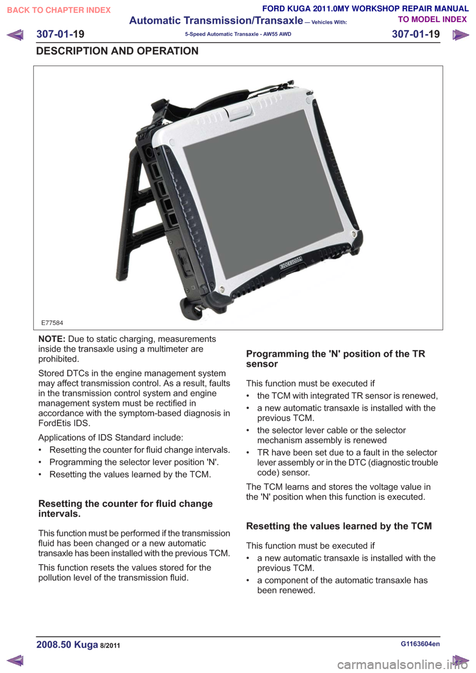
E77584
NOTE:Due to static charging, measurements
inside the transaxle using a multimeter are
prohibited.
Stored DTCs in the engine management system
may affect transmission control. As a result, faults
in the transmission control system and engine
management system must be rectified in
accordance with the symptom-based diagnosis in
FordEtis IDS.
Applications of IDS Standard include:
• Resetting the counter for fluid change intervals.
• Programming the selector lever position 'N'.
• Resetting the values learned by the TCM.
Resetting the counter for fluid change
intervals.
This function must be performed if the transmission
fluid has been changed or a new automatic
transaxle has been installed with the previous TCM.
This function resets the values stored for the
pollution level of the transmission fluid.
Programming the 'N' position of the TR
sensor
This function must be executed if
• the TCM with integrated TR sensor is renewed,
• a new automatic transaxle is installed with the previous TCM.
• the selector lever cable or the selector mechanism assembly is renewed
• TR have been set due to a fault in the selector lever assembly or in the DTC (diagnostic trouble
code) sensor.
The TCM learns and stores the voltage value in
the 'N' position when this function is executed.
Resetting the values learned by the TCM
This function must be executed if
• a new automatic transaxle is installed with the previous TCM.
• a component of the automatic transaxle has been renewed.
G1163604en2008.50 Kuga8/2011
307-01- 19
Automatic Transmission/Transaxle
— Vehicles With:
5-Speed Automatic Transaxle - AW55 AWD
307-01- 19
DESCRIPTION AND OPERATION
TO MODEL INDEX
BACK TO CHAPTER INDEX
FORD KUGA 2011.0MY WORKSHOP REPAIR MANUAL
Page 2008 of 2057

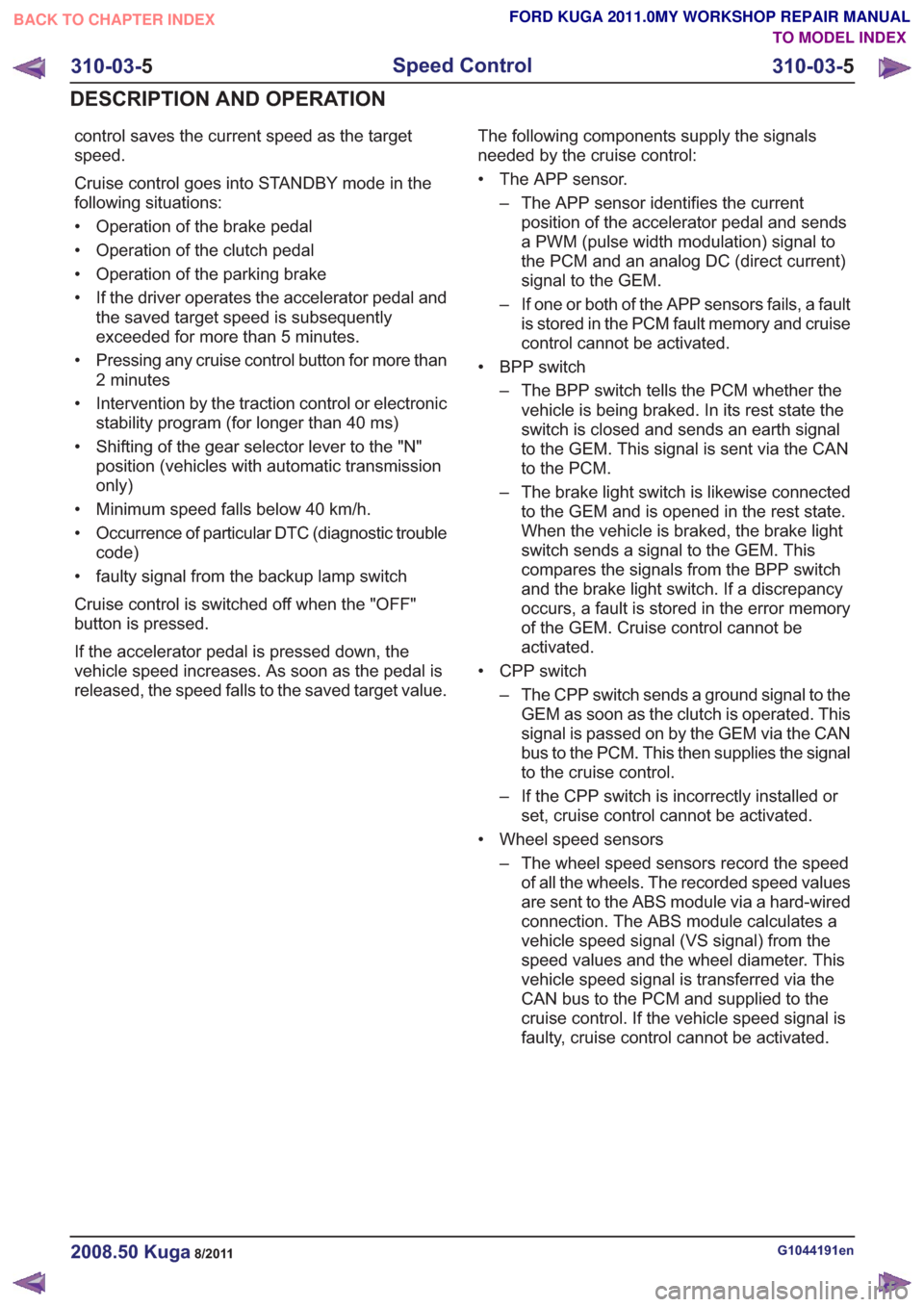
control saves the current speed as the target
speed.
Cruise control goes into STANDBY mode in the
following situations:
• Operation of the brake pedal
• Operation of the clutch pedal
• Operation of the parking brake
• If the driver operates the accelerator pedal andthe saved target speed is subsequently
exceeded for more than 5 minutes.
• Pressing any cruise control button for more than 2 minutes
• Intervention by the traction control or electronic stability program (for longer than 40 ms)
• Shifting of the gear selector lever to the "N" position (vehicles with automatic transmission
only)
• Minimum speed falls below 40 km/h.
• Occurrence of particular DTC (diagnostic trouble code)
• faulty signal from the backup lamp switch
Cruise control is switched off when the "OFF"
button is pressed.
If the accelerator pedal is pressed down, the
vehicle speed increases. As soon as the pedal is
released, the speed falls to the saved target value. The following components supply the signals
needed by the cruise control:
• The APP sensor.
– The APP sensor identifies the currentposition of the accelerator pedal and sends
a PWM (pulse width modulation) signal to
the PCM and an analog DC (direct current)
signal to the GEM.
– If one or both of the APP sensors fails, a fault is stored in the PCM fault memory and cruise
control cannot be activated.
• BPP switch – The BPP switch tells the PCM whether thevehicle is being braked. In its rest state the
switch is closed and sends an earth signal
to the GEM. This signal is sent via the CAN
to the PCM.
– The brake light switch is likewise connected to the GEM and is opened in the rest state.
When the vehicle is braked, the brake light
switch sends a signal to the GEM. This
compares the signals from the BPP switch
and the brake light switch. If a discrepancy
occurs, a fault is stored in the error memory
of the GEM. Cruise control cannot be
activated.
• CPP switch – The CPP switch sends a ground signal to theGEM as soon as the clutch is operated. This
signal is passed on by the GEM via the CAN
bus to the PCM. This then supplies the signal
to the cruise control.
– If the CPP switch is incorrectly installed or set, cruise control cannot be activated.
• Wheel speed sensors – The wheel speed sensors record the speedof all the wheels. The recorded speed values
are sent to the ABS module via a hard-wired
connection. The ABS module calculates a
vehicle speed signal (VS signal) from the
speed values and the wheel diameter. This
vehicle speed signal is transferred via the
CAN bus to the PCM and supplied to the
cruise control. If the vehicle speed signal is
faulty, cruise control cannot be activated.
G1044191en2008.50 Kuga8/2011
310-03- 5
Speed Control
310-03- 5
DESCRIPTION AND OPERATION
TO MODEL INDEX
BACK TO CHAPTER INDEX
FORD KUGA 2011.0MY WORKSHOP REPAIR MANUAL