2011 FORD KUGA Gas
[x] Cancel search: GasPage 1800 of 2057
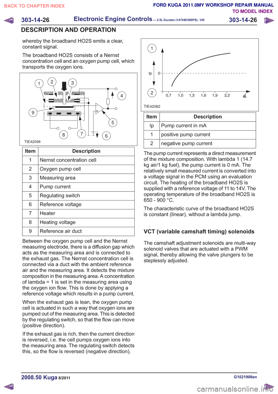
whereby the broadband HO2S emits a clear,
constant signal.
The broadband HO2S consists of a Nernst
concentration cell and an oxygen pump cell, which
transports the oxygen ions.
TIE42098
5
7
9
12
86
4
3
Description
Item
Nernst concentration cell
1
Oxygen pump cell
2
Measuring area
3
Pump current
4
Regulating switch
5
Reference voltage
6
Heater
7
Heating voltage
8
Reference air duct
9
Between the oxygen pump cell and the Nernst
measuring electrode, there is a diffusion gap which
acts as the measuring area and is connected to
the exhaust gas. The Nernst concentration cell is
connected via a duct with the ambient reference
air and the measuring area. It detects the mixture
composition in the measuring area. A concentration
of lambda = 1 is set in the measuring area using
the oxygen ion flow. This is done by applying a
reference voltage which results in a pump current.
When the exhaust gas is lean, the oxygen pump
cell is actuated in such a way that oxygen ions are
pumped out of the measuring area. This is detected
by the regulating switch, so that the flow can move
(positive direction).
If the exhaust gas is rich, then the current direction
is reversed, i.e. the cell pumps oxygen ions into
the measuring area. The regulating switch detects
this, so the flow is reversed (negative direction).
TIE42062
1
2
Description
Item
Pump current in mA
Ip
positive pump current
1
negative pump current
2
The pump current represents a direct measurement
of the mixture composition. With lambda 1 (14.7
kg air/1 kg fuel), the pump current is 0 mA. The
relatively small measured current is converted into
a voltage signal in the PCM using an evaluation
circuit. The heating of the broadband HO2S is
supplied with a reference voltage of 11 to 14V. The
operating temperature of the broadband HO2S is
650 - 900 °C.
The characteristic curve of the broadband HO2S
is constant (linear), without a lambda jump.
VCT (variable camshaft timing) solenoids
The camshaft adjustment solenoids are multi-way
solenoid valves that are actuated with a PWM
signal, thereby allowing the valve plungers to be
steplessly adjusted.
G1021908en2008.50 Kuga8/2011
303-14- 26
Electronic Engine Controls— 2.5L Duratec (147kW/200PS) - VI5303-14-
26
DESCRIPTION AND OPERATION
TO MODEL INDEX
BACK TO CHAPTER INDEX
FORD KUGA 2011.0MY WORKSHOP REPAIR MANUAL
Page 1963 of 2057
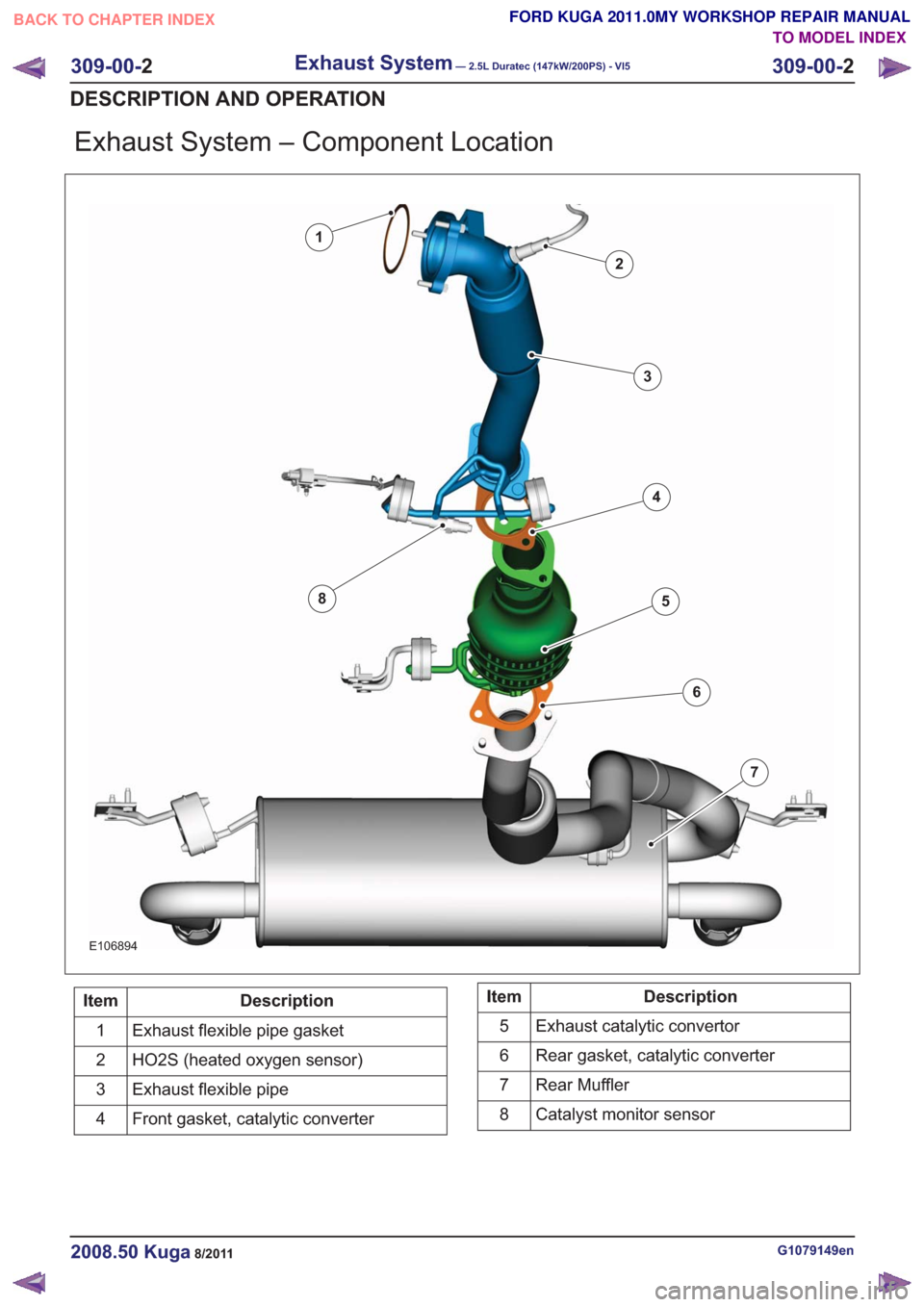
Exhaust System – Component Location
E106894
1
2
3
4
5
6
7
8
Description
Item
Exhaust flexible pipe gasket
1
HO2S (heated oxygen sensor)
2
Exhaust flexible pipe
3
Front gasket, catalytic converter
4Description
Item
Exhaust catalytic convertor
5
Rear gasket, catalytic converter
6
Rear Muffler
7
Catalyst monitor sensor
8
G1079149en2008.50 Kuga8/2011
309-00- 2
Exhaust System— 2.5L Duratec (147kW/200PS) - VI5309-00-
2
DESCRIPTION AND OPERATION
TO MODEL INDEX
BACK TO CHAPTER INDEX
FORD KUGA 2011.0MY WORKSHOP REPAIR MANUAL
Page 1987 of 2057

Description
Item
Latch mechanism
1
Housing, capless fuel filler pipe
2
Overflow
3Description
Item
Gasket
4
Filler nozzle
5
A spring-loaded fuel filler door closes off the upper
end of the fuel tank filler pipe in place of the filler
cap. The spring-loaded fuel filler door features a
latching mechanism. The release mechanism is
matched to the size of the filler nozzle. If the correct
filler nozzle is inserted, the release lugs are pushed
back. This releases the slide which can move
upwards and opens the way to the spring-loaded
fuel filler door for the filler nozzle.
G1090887en2008.50 Kuga8/2011
310-01- 7
Fuel Tank and Lines
310-01- 7
DESCRIPTION AND OPERATION
TO MODEL INDEX
BACK TO CHAPTER INDEX
FORD KUGA 2011.0MY WORKSHOP REPAIR MANUAL
Page 2019 of 2057
Perform the leak test, by closing the hand valves
on the gauge set, switching off the service unit
vacuum pump and observing the low pressure
gauge.
10. N O T E : This step is only necessary if the
pressure increase exceeds 20 mbar.
Locate and rectify any leaks in the A/C
refrigerant circuit using a leak tester.
General Equipment: UV Leak Detector
General Equipment: Electronic Leak Detector
General Equipment: Automatic Calibration Halogen Leak Detector
11 . Add refrigerant oil to the air conditioning system.
Refer to: Specifications (412-00 Climate Control
System - General Information, Specifications).
Refer to: Refrigerant Oil Adding (412-00 Climate
Control System - General Information, General
Procedures).
12. Fill the air conditioning system with liquid
through the high-pressure connection.
Refer to: Specifications (412-00 Climate Control
System - General Information, Specifications).
13. Open the shut-off valve on the high-pressure
side.
1.
2. Switch the service unit to "Fill" mode and fill
the system with the specified quantity of
liquid refrigerant (R134a).
14. Fill the air conditioning system with gas through
the low-pressure connection.
Refer to: Specifications (412-00 Climate Control
System - General Information, Specifications).
15. Open the shut-off valve on the low-pressure
side.
1.
2. Switch the service unit to "Fill" mode and fill
the system with the specified quantity of
gaseous refrigerant.
3. Add the remaining amount of refrigerant with the air conditioning switched on. To do so
run the engine at about 1200-1500 rev/min.
Set the air conditioning system to full cooling
power and fresh air mode. Set the blower
motor to the highest setting. Fill with the
remainder of the specified fill capacity.
16. Disconnect the service unit. 17.
Close the shut-off valve.
1.
2. Switch off the service unit.
3. Disconnect the service unit lines from the
filling connections of the air conditioning
system.
4. Screw the protective caps onto the charging connections.
18. Install all components in reverse order.
G1022208en2008.50 Kuga8/2011
412-00- 8
Climate Control System - General Information
412-00- 8
GENERAL PROCEDURES
TO MODEL INDEX
BACK TO CHAPTER INDEX
FORD KUGA 2011.0MY WORKSHOP REPAIR MANUAL
Page 2025 of 2057
Electronic Leak Detection
1.Refer to: Air Conditioning (A/C) System Health
and Safety Precautions (100-00 General
Information, Description and Operation).
2. WARNINGS:
Before starting leak detection, make
sure that the area where it is to be done
is well ventilated. If the surrounding air
is contaminated with refrigerant gas, the
leak detector will indicate this gas all
the time. Odors from other chemicals
such as antifreeze, diesel fuel, disc
brake cleaner, or other cleaning
solvents can cause the same problem.
Prevent air movement while performing
leak detection.
The refrigerant identification equipment
must be used before attaching the
manifold gauge set. Otherwise the
manifold gauge set may become
contaminated. Contaminated refrigerant
must be disposed of as special waste.
Follow the manufacturer's instructions
when working with the service unit.
NOTE: At 24°C with the engine switched off,
both manifold gauges should show 4.1 to 5.5
bar.
Attach the manifold gauge set to the service
gauge port valves.
3. For the leak test, close the manual valves on
the gauge set.
4. If little or no pressure is indicated, charge the
system with approx. 300g of refrigerant. Refer
to: Air Conditioning System - Evacuate and
Refill.
5. Use the R-134a Automatic Calibration Halogen
Leak Detector to leak test the refrigerant system.
Follow the instructions included with leak
detector for handling and operation techniques.
6. If any leak is found, extract the refrigerant under
suction. Refer to: Air Conditioning System -
Evacuate and Refill.
G549836en2008.50 Kuga8/2011
412-00- 14
Climate Control System - General Information
412-00- 14
GENERAL PROCEDURES
TO MODEL INDEX
BACK TO CHAPTER INDEX
FORD KUGA 2011.0MY WORKSHOP REPAIR MANUAL
Page 2050 of 2057
1
2
3
5
4
67
8
9
10
11
E100819
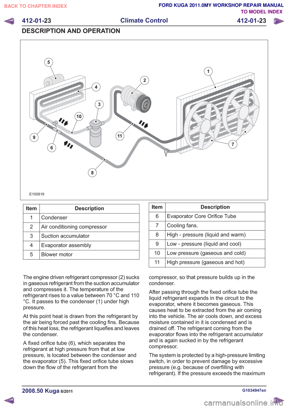
Description
Item
Condenser
1
Air conditioning compressor
2
Suction accumulator
3
Evaporator assembly
4
Blower motor
5Description
Item
Evaporator Core Orifice Tube
6
Cooling fans.
7
High - pressure (liquid and warm)
8
Low - pressure (liquid and cool)
9
Low pressure (gaseous and cold)
10
High pressure (gaseous and hot)
11
The engine driven refrigerant compressor (2) sucks
in gaseous refrigerant from the suction accumulator
and compresses it. The temperature of the
refrigerant rises to a value between 70 °C and 110
°C. It passes to the condenser (1) under high
pressure.
At this point heat is drawn from the refrigerant by
the air being forced past the cooling fins. Because
of this heat loss, the refrigerant liquefies and leaves
the condenser.
A fixed orifice tube (6), which separates the
refrigerant at high pressure from that at low
pressure, is located between the condenser and
the evaporator (5). This fixed orifice tube slows
down the flow of the refrigerant from the compressor, so that pressure builds up in the
condenser.
After passing through the fixed orifice tube the
liquid refrigerant expands in the circuit to the
evaporator, where it becomes gaseous. This
causes heat to be extracted from the air coming
into the vehicle. The air cools down, and excess
moisture contained in it is condensed and is
drained off. The refrigerant coming from the
evaporator flows into the refrigerant accumulator
and is again sucked in by the refrigerant
compressor.
The system is protected by a high-pressure limiting
switch, in order to prevent damage by excessive
pressure (e.g. because of overfilling with
refrigerant). If the pressure exceeds the maximum
G1034947en2008.50 Kuga8/2011
412-01-
23
Climate Control
412-01- 23
DESCRIPTION AND OPERATION
TO MODEL INDEX
BACK TO CHAPTER INDEX
FORD KUGA 2011.0MY WORKSHOP REPAIR MANUAL