Page 1327 of 2057
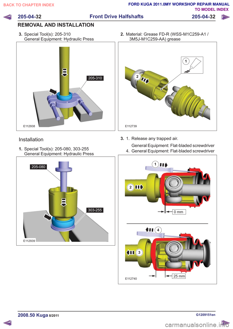
3.Special Tool(s): 205-310
General Equipment: Hydraulic Press
205-310205-310
E112938
Installation
1.Special Tool(s): 205-080, 303-255
General Equipment: Hydraulic Press
205-080
303-255
205-080
303-255
E112939
2.Material: Grease FD-R (WSS-M1C259-A1 /
3M5J-M1C259-AA) grease
1
2
E112739
3. Release any trapped air.
General Equipment: Flat-bladed screwdriver
1.
4. General Equipment: Flat-bladed screwdriver
25 mm
0mm
1
2
25 mm
0mm
3
4
E112740
G1209151en2008.50 Kuga8/2011
205-04-
32
Front Drive Halfshafts
205-04- 32
REMOVAL AND INSTALLATION
TO MODEL INDEX
BACK TO CHAPTER INDEX
FORD KUGA 2011.0MY WORKSHOP REPAIR MANUAL
Page 1421 of 2057
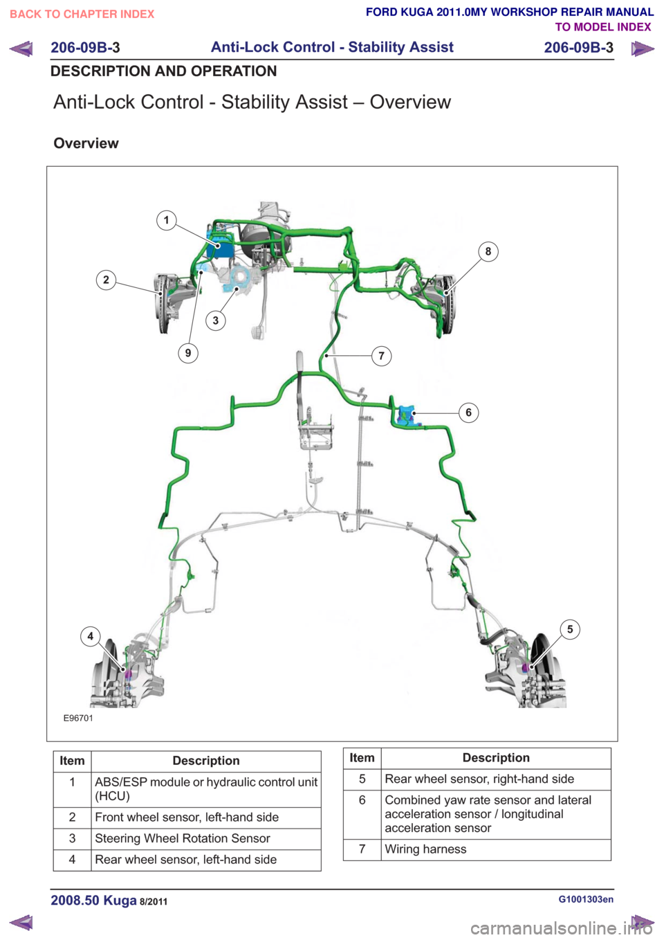
Anti-Lock Control - Stability Assist – Overview
Overview
E96701
1
2
3
45
6
7
8
9
Description
Item
ABS/ESP module or hydraulic control unit
(HCU)
1
Front wheel sensor, left-hand side
2
Steering Wheel Rotation Sensor
3
Rear wheel sensor, left-hand side
4Description
Item
Rear wheel sensor, right-hand side
5
Combined yaw rate sensor and lateral
acceleration sensor / longitudinal
acceleration sensor
6
Wiring harness
7
G1001303en2008.50 Kuga8/2011
206-09B- 3
Anti-Lock Control - Stability Assist
206-09B- 3
DESCRIPTION AND OPERATION
TO MODEL INDEX
BACK TO CHAPTER INDEX
FORD KUGA 2011.0MY WORKSHOP REPAIR MANUAL
Page 1422 of 2057
Description
Item
Front wheel sensor, right-hand side
8Description
Item
9 ESP switch
Testing the brakes on a roller dynamometer
- 4X4 vehicles only
On 4X4 vehicles a brake test on a roller
dynamometer must only be performed under the
following conditions.
• The brake test must not exceed a duration of 1 minute.
• Ignition key in position 0.
• The roller speed must not exceed 5 km/h.
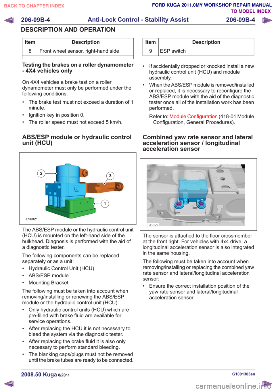
ABS/ESP module or hydraulic control
unit (HCU)
E96821
1
23
The ABS/ESP module or the hydraulic control unit
(HCU) is mounted on the left-hand side of the
bulkhead. Diagnosis is performed with the aid of
a diagnostic tester.
The following components can be replaced
separately or as a unit:
• Hydraulic Control Unit (HCU)
• ABS/ESP module
• Mounting Bracket
The following must be taken into account when
removing/installing or renewing the ABS/ESP
module or the hydraulic control unit (HCU):
• Only hydraulic control units (HCU) which are pre-filled with brake fluid are available for
service operations.
• After replacing the HCU it is not necessary to bleed the system via the diagnostic tester.
• After replacing the brake fluid it is also only necessary to perform standard bleeding.
• The blanking caps/plugs must not be removed until the brake tubes are ready to be connected. • If accidentally dropped or knocked install a new
hydraulic control unit (HCU) and module
assembly.
• When the ABS/ESP module is removed/installed or replaced, it is necessary to reconfigure the
ABS/ESP module with the aid of the diagnostic
tester once all of the installation work has been
performed.
Refer to: Module Configuration (418-01 Module
Configuration, General Procedures).
Combined yaw rate sensor and lateral
acceleration sensor / longitudinal
acceleration sensor
E96822
The sensor is attached to the floor crossmember
at the front right. For vehicles with 4x4 drive, a
longitudinal acceleration sensor is also integrated
in the same housing.
The following must be taken into account when
removing/installing or replacing the combined yaw
rate sensor and lateral/longitudinal acceleration
sensor:
• Ensure the correct installation position of the yaw rate sensor and lateral/longitudinal
acceleration sensor.
G1001303en2008.50 Kuga8/2011
206-09B- 4
Anti-Lock Control - Stability Assist
206-09B- 4
DESCRIPTION AND OPERATION
TO MODEL INDEX
BACK TO CHAPTER INDEX
FORD KUGA 2011.0MY WORKSHOP REPAIR MANUAL
Page 1423 of 2057
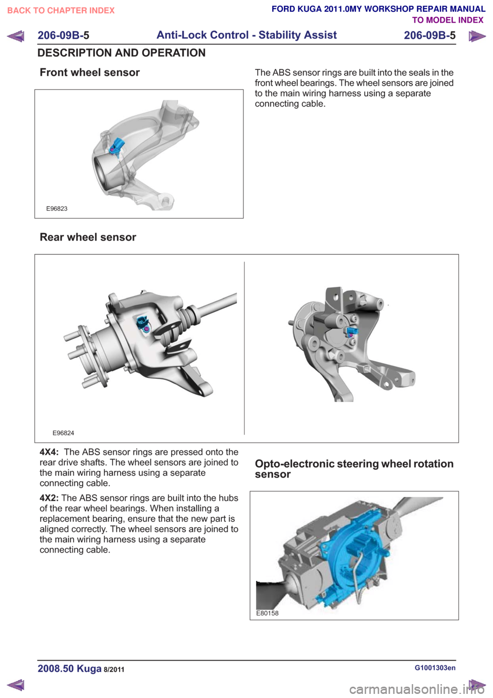
Front wheel sensor
E96823
The ABS sensor rings are built into the seals in the
front wheel bearings. The wheel sensors are joined
to the main wiring harness using a separate
connecting cable.
Rear wheel sensor
E96824
4X4:The ABS sensor rings are pressed onto the
rear drive shafts. The wheel sensors are joined to
the main wiring harness using a separate
connecting cable.
4X2: The ABS sensor rings are built into the hubs
of the rear wheel bearings. When installing a
replacement bearing, ensure that the new part is
aligned correctly. The wheel sensors are joined to
the main wiring harness using a separate
connecting cable.
Opto-electronic steering wheel rotation
sensor
E80158
G1001303en2008.50 Kuga8/2011
206-09B- 5
Anti-Lock Control - Stability Assist
206-09B- 5
DESCRIPTION AND OPERATION
TO MODEL INDEX
BACK TO CHAPTER INDEX
FORD KUGA 2011.0MY WORKSHOP REPAIR MANUAL
Page 1424 of 2057
Vehicles with ESP are equipped with an
opto-electronic steering wheel rotation sensor as
an integral part of the clockspring.
The following must be taken into account when
removing/installing or replacing the opto-electronic
steering wheel rotation sensor:
• If installing a new clockspring, remove theclockspring locking screw.
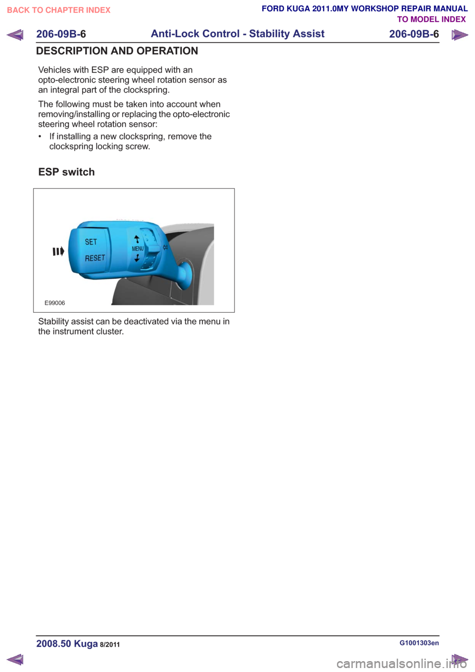
ESP switch
E99006
Stability assist can be deactivated via the menu in
the instrument cluster.
G1001303en2008.50 Kuga8/2011
206-09B- 6
Anti-Lock Control - Stability Assist
206-09B- 6
DESCRIPTION AND OPERATION
TO MODEL INDEX
BACK TO CHAPTER INDEX
FORD KUGA 2011.0MY WORKSHOP REPAIR MANUAL
Page 1450 of 2057
Power Steering System Filling
Special Tool(s)211-189
Adapter, Power Steering
Bleeding
13016
416-D001
Hand Vacuum
Pump/Pressure Pump
23036A
Materials
Specification
Name
WSS-M2C204-A2 /
5U7J-M2C204-AA
Hydraulic Fluid DP-PS
1. Fill the power steering fluid reservoir to the MAX
mark.
Material: Hydraulic Fluid DP-PS
(WSS-M2C204-A2 / 5U7J-M2C204-AA)
hydraulic fluid
2. Raise the vehicle until the road wheels are clear
of the floor. Support the vehicle.
Refer to: Lifting(100-02 Jacking and Lifting,
Description and Operation).
3. Slowly turn the steering wheel from lock to lock
and add power steering fluid until the power
steering fluid in the power steering fluid reservoir
stops dropping.
4. Start the engine and slowly turn the steering
wheel from lock to lock and add power steering
fluid until the power steering fluid in the power
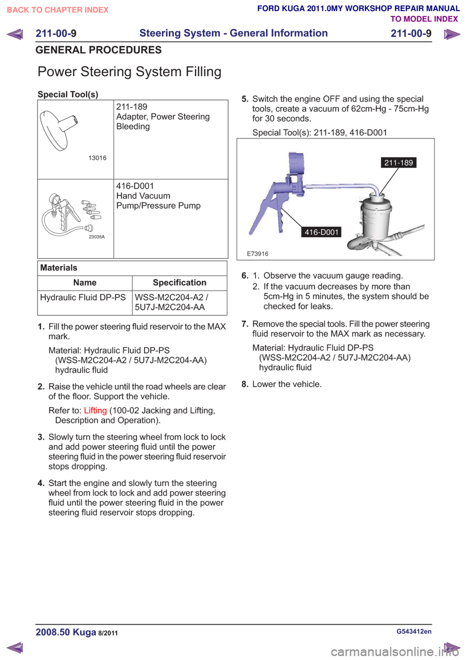
steering fluid reservoir stops dropping. 5.
Switch the engine OFF and using the special
tools, create a vacuum of 62cm-Hg - 75cm-Hg
for 30 seconds.
Special Tool(s): 211-189, 416-D001
E73916
211-189
416-D001
6. Observe the vacuum gauge reading.
1.
2. If the vacuum decreases by more than
5cm-Hg in 5 minutes, the system should be
checked for leaks.
7. Remove the special tools. Fill the power steering
fluid reservoir to the MAX mark as necessary.
Material: Hydraulic Fluid DP-PS
(WSS-M2C204-A2 / 5U7J-M2C204-AA)
hydraulic fluid
8. Lower the vehicle.
G543412en2008.50 Kuga8/2011
211-00- 9
Steering System - General Information
211-00- 9
GENERAL PROCEDURES
TO MODEL INDEX
BACK TO CHAPTER INDEX
FORD KUGA 2011.0MY WORKSHOP REPAIR MANUAL
Page 1451 of 2057
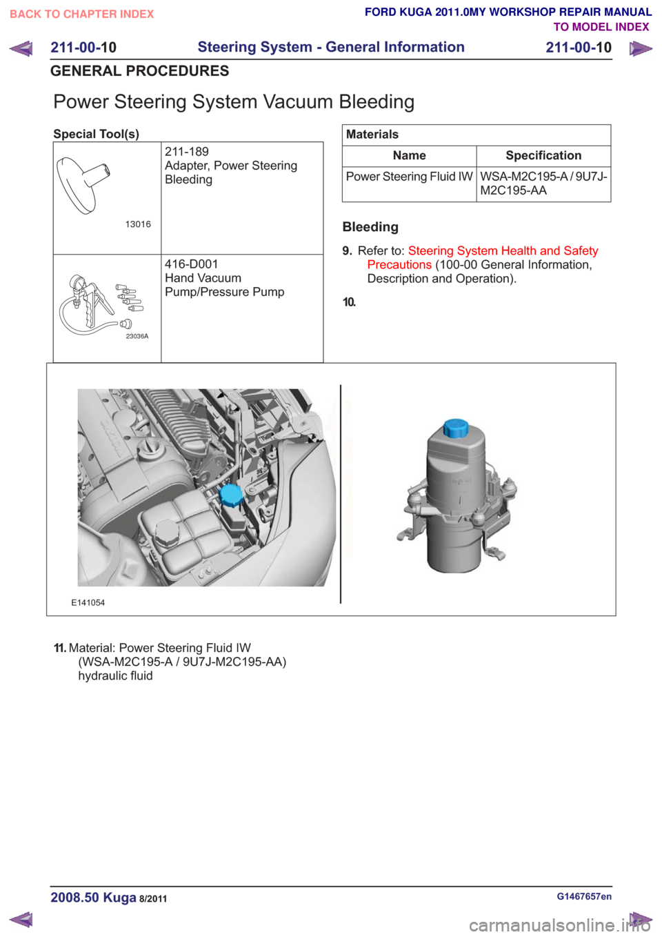
Power Steering System Vacuum Bleeding
Special Tool(s)211-189
Adapter, Power Steering
Bleeding
13016
416-D001
Hand Vacuum
Pump/Pressure Pump
23036A
Materials
Specification
Name
WSA-M2C195-A / 9U7J-
M2C195-AA
Power Steering Fluid IW
Bleeding
9.
Refer to: Steering System Health and Safety
Precautions (100-00 General Information,
Description and Operation).
10.
E141054
11 . Material: Power Steering Fluid IW
(WSA-M2C195-A / 9U7J-M2C195-AA)
hydraulic fluid
G1467657en2008.50 Kuga8/2011
211-00- 10
Steering System - General Information
211-00- 10
GENERAL PROCEDURES
TO MODEL INDEX
BACK TO CHAPTER INDEX
FORD KUGA 2011.0MY WORKSHOP REPAIR MANUAL
Page 1517 of 2057
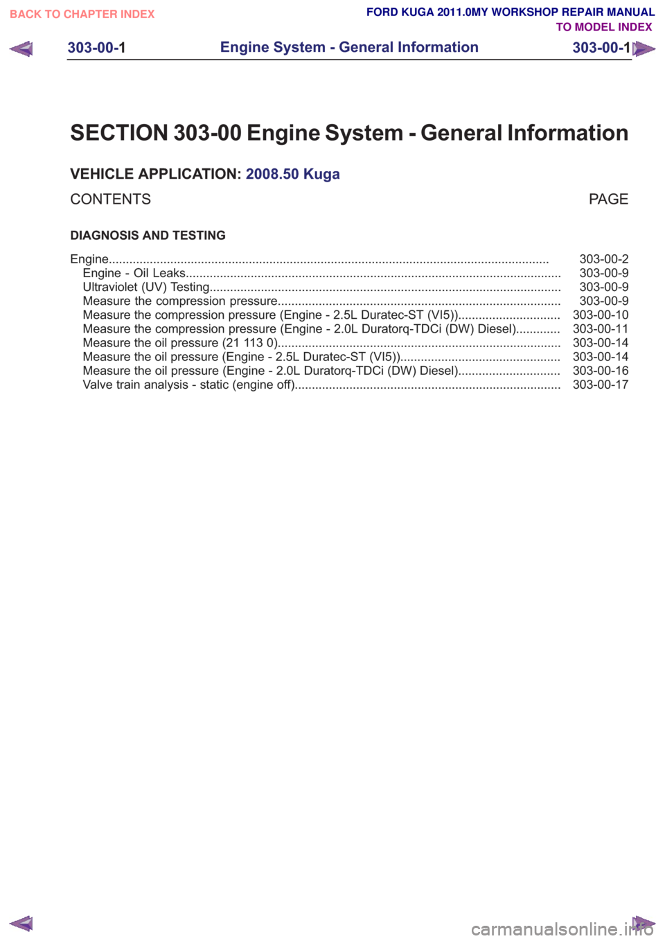
SECTION 303-00 Engine System - General Information
VEHICLE APPLICATION:2008.50 Kuga
PA G E
CONTENTS
DIAGNOSIS AND TESTING
303-00-2
Engine ........................................................................\
.........................................................
303-00-9
Engine - Oil Leaks ........................................................................\
......................................
303-00-9
Ultraviolet (UV) Testing ........................................................................\
...............................
303-00-9
Measure the compression pressure ........................................................................\
...........
303-00-10
Measure the compression pressure (Engine - 2.5L Duratec-ST (VI5)) ..............................
303-00-11
Measure the compression pressure (Engine - 2.0L Duratorq-TDCi (DW) Diesel) .............
303-00-14
Measure the oil pressure (21 113 0) ........................................................................\
...........
303-00-14
Measure the oil pressure (Engine - 2.5L Duratec-ST (VI5)) ...............................................
303-00-16
Measure the oil pressure (Engine - 2.0L Duratorq-TDCi (DW) Diesel) ..............................
303-00-17
Valve train analysis - static (engine off) ........................................................................\
......
303-00-1
Engine System - General Information
303-00- 1
.
TO MODEL INDEX
BACK TO CHAPTER INDEX
FORD KUGA 2011.0MY WORKSHOP REPAIR MANUAL