2011 FORD KUGA warning light
[x] Cancel search: warning lightPage 190 of 2057

Instrument Cluster
Refer to
Wiring Diagrams Section 413-01, for
schematic and connector information. General Equipment
The Ford approved diagnostic tool
Inspection and Verification
1. Verify the customer concern.
2. Visually inspect for obvious signs of mechanical
or electrical damage.
Visual Inspection Chart Electrical
Mechanical
– Fuse(s)
– Wiring harness
– Electricalconnector(s)
– Instrument cluster
– Light emitting diode(s) (LED)(s)
– Engine oil filter
– Engine oil level
–
Engine coolant level
– Oil pressure switch
– Engine coolant level
– Coolant thermostat
– Engine coolant temperature (ECT)
sensor
– Fuel gauge
– Collapsed or damaged fuel tank
– Recirculation hose
– Fuel tank filler pipe/hose
– Indicated fuel level
– Fuel lines
– Fuel tank filler cap
– Fuel filter (external to the fuel tank)
– Fuel tank
– Door adjustment
3. If an obvious cause for an observed or reported concern is found, correct the cause (if possible)
before proceeding to the next step.
4. NOTE: If none of the following warning indicators are operating correctly this may
indicate a concern with the central junction
box (CJB). If only one or two of the following
warning indicators are not operating
correctly this may indicate an instrument
cluster concern. Verify the following warning indicators are
working correctly:
• Charging.
• Turn signals.
• Headlamps.
5. If the cause is not visually evident, verify the symptom and refer to the diagnostic tab within
the Ford approved diagnostic tool.
Configuration of the Instrument Cluster
The instrument cluster is a programmable module,
which must be configured by selecting the
Programmable Module Installation Routine on the
Ford approved diagnostic tool.
NOTE: When the new instrument cluster has been
configured with the odometer value, its
configuration cannot be decreased or matched. A
new configuration will result in an increase in the
displayed odometer value by a minimum of two
units.
NOTE: The odometer value must be recorded from
the original instrument cluster before removal.
If the odometer value cannot be obtained from
the original instrument cluster (display failure)
the customer should supply the approximate
value.
The following features will need to be configured
when a new instrument cluster is installed:
• Anti-lock Brake System (ABS)
• All wheel drive
• Keyless vehicle entry
• Electronic power assisted steering
• Trip computer
• Voice control
• Parking aid
• Belt minder
• Safety belt not fastened
• Right hand drive
• Overspeed warning
• Reverse warning
• Turbocharger boost pressure
• Speed control
• Auxiliary heater
• Suspension control
• Washer fluid sensor G1054964en
2008.50 Kuga 8/2011 413-01-7
Instrument Cluster
413-01-7
DIAGNOSIS AND TESTINGTO MODEL INDEX
BACK TO CHAPTER INDEX
FORD KUGA 2011.0MY WORKSHOP REPAIR MANUAL
Page 263 of 2057

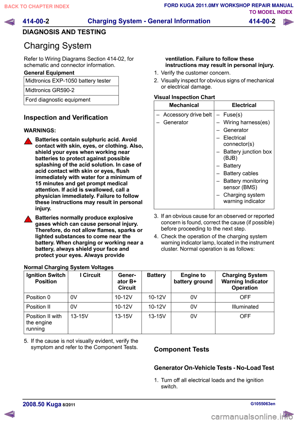
Charging System
Refer to Wiring Diagrams Section 414-02, for
schematic and connector information.
General Equipment
Midtronics EXP-1050 battery tester
Midtronics GR590-2
Ford diagnostic equipment
Inspection and Verification
WARNINGS: Batteries contain sulphuric acid. Avoid
contact with skin, eyes, or clothing. Also,
shield your eyes when working near
batteries to protect against possible
splashing of the acid solution. In case of
acid contact with skin or eyes, flush
immediately with water for a minimum of
15 minutes and get prompt medical
attention. If acid is swallowed, call a
physician immediately. Failure to follow
these instructions may result in personal
injury.
Batteries normally produce explosive
gases which can cause personal injury.
Therefore, do not allow flames, sparks or
lighted substances to come near the
battery. When charging or working near a
battery, always shield your face and
protect your eyes. Always provide
ventilation. Failure to follow these
instructions may result in personal injury.
1. Verify the customer concern.
2. Visually inspect for obvious signs of mechanical
or electrical damage.
Visual Inspection Chart Electrical
Mechanical
– Fuse(s)
– Wiring harness(es)
– Generator
– Electricalconnector(s)
– Battery junction box (BJB)
– Battery
– Battery cables
– Battery monitoring sensor (BMS)
– Charging system warning indicator
–
Accessory drive belt
– Generator
3. If an obvious cause for an observed or reported concern is found, correct the cause (if possible)
before proceeding to the next step.
4. Check the operation of the charging system warning indicator lamp, located in the instrument
cluster. Normal operation is as follows:
Normal Charging System Voltages Charging System
Warning Indicator Operation
Engine to
battery ground
Battery
Gener-
ator B+ Circuit
I Circuit
Ignition Switch
Position
OFF
0V
10-12V
10-12V
0V
Position 0
Illuminated
0V
10-12V
10-12V
0V
Position II
OFF
0V
13-15V
13-15V
13-15V
Position II with
the engine
running
5. If the cause is not visually evident, verify the symptom and refer to the Component Tests. Component Tests
Generator On-Vehicle Tests - No-Load Test
1. Turn off all electrical loads and the ignition
switch. G1055063en
2008.50 Kuga 8/2011 414-00-2
Charging System - General Information
414-00-2
DIAGNOSIS AND TESTINGTO MODEL INDEX
BACK TO CHAPTER INDEX
FORD KUGA 2011.0MY WORKSHOP REPAIR MANUAL
Page 270 of 2057

Battery Disconnect and Connect
Disconnect
WARNINGS:
Batteries normally produce explosive
gases which may cause personal injury,
therefore do not allow flames, sparks or
lighted substances to come near the
battery. When charging or working near
the battery always shield your face and
protect your eyes. Always provide
adequate ventilation. Failure to follow
these instructions may result in personal
injury.
The supplemental restraint system (SRS)
is active for a certain length of time after
the power supply has been disconnected.
Wait for a minimum of 3 minutes before
disconnecting or removing any SRS
components.
Audio unit key code saving devices must
not be used when working on
supplemental restraint or fuel systems.
When using these devices the vehicle
electrical system is still live but with a
reduced current flow. Failure to follow this
instruction may result in personal injury.
CAUTION: Make sure the engine is not
running before disconnecting the battery
ground cable to avoid damage to the
vehicle electrical system.
NOTE: Disconnecting the battery will erase fault
codes, drive values and customer data stored in
the modules.
NOTE: This procedure should be used to
disconnect the battery while carrying out repairs
that refer to the battery being disconnected.
1. Refer to: Battery and Battery Charging Health
and Safety Precautions (100-00 General
Information, Description and Operation).
2. Obtain and record the audio unit keycode and
preset radio frequencies. 3.
G1062389en
2008.50 Kuga 8/2011 414-01-2
Battery, Mounting and Cables
414-01-2
GENERAL PROCEDURESTO MODEL INDEX
BACK TO CHAPTER INDEX
FORD KUGA 2011.0MY WORKSHOP REPAIR MANUALE103137
Page 279 of 2057

Direct Current/Alternating Current (DC/AC) Inverter – Overview
Function indicator
WARNING: For workshop repairs, it is only
permissible to replace the converter as a
complete unit together with the wiring
harness and the socket. The component
must not be opened, as charged capacitors
inside can still carry dangerously high
residual voltages.
The LED in the socket lights up orange when the
converter is supplying a voltage.
In the event of a fault the system switches off and
indicates the cause of the fault by flashing a trouble
code via the LED in the socket:
• 1x flash – High temperature
• 2x flashes – Overload
• 3x flashes – Internal overvoltage
• 4x flashes – Internal undervoltage
• Continuous flashing – Short circuit to power
If the converter switches off due to high
temperature then it switches back on again
automatically once the temperature has cooled
down sufficiently.
With all of the other faults which are displayed, the
converter can be reset by switching the ignition off
and back on again or by unplugging and reinserting
the consumer in the socket.
If these measures are unsuccessful then there are
no further options for directly influencing the
function yourself. G1055637en
2008.50 Kuga 8/2011 414-05-3
Voltage Converter/Inverter
414-05-3
DESCRIPTION AND OPERATIONTO MODEL INDEX
BACK TO CHAPTER INDEX
FORD KUGA 2011.0MY WORKSHOP REPAIR MANUAL
Page 341 of 2057

Combined rain sensor/light sensor
CAUTIONS:
On vehicles with autolamps, retrofitting
with daytime running lamps is not
permissible, as otherwise, the engine
cannot be stopped when the lighting is
switched on.
On vehicles with autolamps, the daytime
running lamp fuse must not be fitted, as
otherwise, the engine cannot be stopped
when the lighting is switched on.
The combined rain sensor/light sensor is located
behind the interior rear view mirror.
autolamps The low beams, side lamps, license plate lamps
as well as the instrument cluster and instrument
panel illumination are switched on automatically if
all the following conditions are met:
• Ignition ON
• Light switch in the "AUTO" position
•
Detected ambient light conditions below a stored
threshold value
These are switched on and off by the GEM (generic
electronic module) in accordance with the input
signals from the combined rain/light sensor.
Headlamp switch-off delay
In vehicles with mid to high-end equipment, the
headlamp switch-off delay uses the dipped beam
headlamps and the door entry illumination (if
equipped) to illuminate the vehicle surroundings.
This function is activated by operating the main
beam headlamp lever with the ignition switched
off. After the last door has been closed, the function
remains active for a further 30 seconds and then
switches off automatically.
When a door or the tailgate is open, the switch-off
time is extended to 180 seconds. After the last door
has been closed, the switch-off time is reset to 30
seconds.
The headlamp switch-off delay can be deactivated
prematurely by operating the high beam lever again
or by switching on the ignition.
The switch-off time is adjusted to fixed values at
the factory and can
notbe re-programmed using
WDS.
Turn signals The turn signals and the warning lamp flash at a
specified frequency and, in the case of failure of a
turn signal, the frequency is doubled.
The turn signal lamps also have a one-touch lane
change function. If the multifunction lever is
pressed just slightly then the relevant turn signal
lamp is actuated 3 times.
Door entry illumination
G1079626en
2008.50 Kuga 8/2011 417-01-7
Exterior Lighting
417-01-7
DESCRIPTION AND OPERATIONTO MODEL INDEX
BACK TO CHAPTER INDEX
FORD KUGA 2011.0MY WORKSHOP REPAIR MANUALE101615 E101616 E101617
Page 346 of 2057

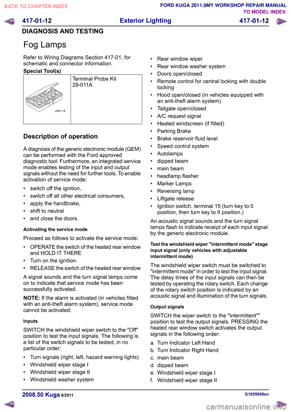
Fog Lamps
Refer to Wiring Diagrams Section 417-01, for
schematic and connector information.
Special Tool(s)
Terminal Probe Kit
29-011ADescription of operation
A diagnosis of the generic electronic module (GEM)
can be performed with the Ford approved
diagnostic tool. Furthermore, an integrated service
mode enables testing of the input and output
signals without the need for further tools. To enable
activation of service mode:
• switch off the ignition,
• switch off all other electrical consumers,
• apply the handbrake,
• shift to neutral
• and close the doors.
Activating the service mode
Proceed as follows to activate the service mode:
•
OPERATE the switch of the heated rear window
and HOLD IT THERE
• Turn on the ignition.
• RELEASE the switch of the heated rear window
A signal sounds and the turn signal lamps come
on to indicate that service mode has been
successfully activated.
NOTE: If the alarm is activated (in vehicles fitted
with an anti-theft alarm system), service mode
cannot be activated.
Inputs
SWITCH the windshield wiper switch to the "Off"
position to test the input signals. The following is
a list of the switch signals to be tested, in no
particular order:
• Turn signals (right, left, hazard warning lights)
• Windshield wiper stage I
• Windshield wiper stage II
• Windshield washer system • Rear window wiper
• Rear window washer system
• Doors open/closed
• Remote control for central locking with double
locking
• Hood open/closed (in vehicles equipped with an anti-theft alarm system)
• Tailgate open/closed
• A/C request signal
• Heated windscreen (if fitted)
• Parking Brake
• Brake reservoir fluid level
• Speed control system
• Autolamps
• dipped beam
• main beam
• headlamp flasher
• Marker Lamps
• Reversing lamp
• Liftgate release
• Ignition switch, terminal 15 (turn key to 0 position, then turn key to II position.)
An acoustic signal sounds and the turn signal
lamps flash to indicate receipt of each input signal
by the generic electronic module.
Test the windshield wiper "intermittent mode" stage
input signal (only vehicles with adjustable
intermittent mode)
The windshield wiper switch must be switched to
"intermittent mode" in order to test the input signal.
The delay times of the input signals can then be
tested by operating the rotary switch. Each change
of the rotary switch position is indicated by an
acoustic signal and illumination of the turn signals.
Output signals
SWITCH the wiper switch to the "intermittent""
position to test the output signals. PRESSING the
heated rear window switch activates the output
signals in the following order:
a. Turn Indicator Left Hand
b. Turn Indicator Right Hand
c. main beam
d. dipped beam
e. Windshield wiper stage I
f. Windshield wiper stage II G1055006en
2008.50 Kuga 8/2011 417-01-12
Exterior Lighting
417-01-12
DIAGNOSIS AND TESTINGTO MODEL INDEX
BACK TO CHAPTER INDEX
FORD KUGA 2011.0MY WORKSHOP REPAIR MANUAL29011A
Page 349 of 2057

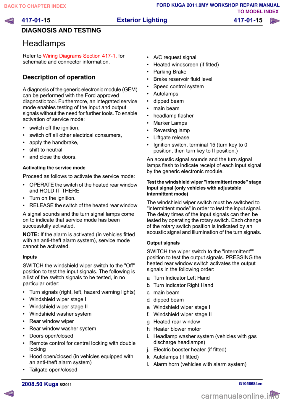
Headlamps
Refer to
Wiring Diagrams Section 417-1, for
schematic and connector information.
Description of operation
A diagnosis of the generic electronic module (GEM)
can be performed with the Ford approved
diagnostic tool. Furthermore, an integrated service
mode enables testing of the input and output
signals without the need for further tools. To enable
activation of service mode:
• switch off the ignition,
• switch off all other electrical consumers,
• apply the handbrake,
• shift to neutral
• and close the doors.
Activating the service mode
Proceed as follows to activate the service mode:
• OPERATE the switch of the heated rear window
and HOLD IT THERE
• Turn on the ignition.
• RELEASE the switch of the heated rear window
A signal sounds and the turn signal lamps come
on to indicate that service mode has been
successfully activated.
NOTE: If the alarm is activated (in vehicles fitted
with an anti-theft alarm system), service mode
cannot be activated.
Inputs
SWITCH the windshield wiper switch to the "Off"
position to test the input signals. The following is
a list of the switch signals to be tested, in no
particular order:
• Turn signals (right, left, hazard warning lights)
• Windshield wiper stage I
• Windshield wiper stage II
• Windshield washer system
• Rear window wiper
• Rear window washer system
• Doors open/closed
• Remote control for central locking with double locking
• Hood open/closed (in vehicles equipped with an anti-theft alarm system)
• Tailgate open/closed • A/C request signal
• Heated windscreen (if fitted)
• Parking Brake
• Brake reservoir fluid level
• Speed control system
• Autolamps
• dipped beam
• main beam
• headlamp flasher
• Marker Lamps
• Reversing lamp
• Liftgate release
• Ignition switch, terminal 15 (turn key to 0
position, then turn key to II position.)
An acoustic signal sounds and the turn signal
lamps flash to indicate receipt of each input signal
by the generic electronic module.
Test the windshield wiper "intermittent mode" stage
input signal (only vehicles with adjustable
intermittent mode)
The windshield wiper switch must be switched to
"intermittent mode" in order to test the input signal.
The delay times of the input signals can then be
tested by operating the rotary switch. Each change
of the rotary switch position is indicated by an
acoustic signal and illumination of the turn signals.
Output signals
SWITCH the wiper switch to the "intermittent""
position to test the output signals. PRESSING the
heated rear window switch activates the output
signals in the following order:
a. Turn Indicator Left Hand
b. Turn Indicator Right Hand
c. main beam
d. dipped beam
e. Windshield wiper stage I
f. Windshield wiper stage II
g. Heated rear window
h. Heater blower motor
i. Headlamp washer system (vehicles with gas discharge headlamps)
j. Electric booster heater (if fitted)
k. Autolamps (if fitted)
l. Alarm horn (vehicles with alarm system) G1056684en
2008.50 Kuga 8/2011 417-01-15
Exterior Lighting
417-01-15
DIAGNOSIS AND TESTINGTO MODEL INDEX
BACK TO CHAPTER INDEX
FORD KUGA 2011.0MY WORKSHOP REPAIR MANUAL
Page 351 of 2057

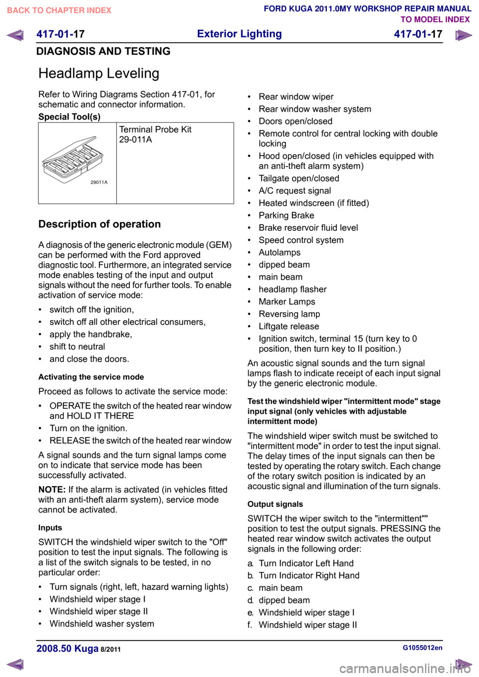
Headlamp Leveling
Refer to Wiring Diagrams Section 417-01, for
schematic and connector information.
Special Tool(s)
Terminal Probe Kit
29-011ADescription of operation
A diagnosis of the generic electronic module (GEM)
can be performed with the Ford approved
diagnostic tool. Furthermore, an integrated service
mode enables testing of the input and output
signals without the need for further tools. To enable
activation of service mode:
• switch off the ignition,
• switch off all other electrical consumers,
• apply the handbrake,
• shift to neutral
• and close the doors.
Activating the service mode
Proceed as follows to activate the service mode:
•
OPERATE the switch of the heated rear window
and HOLD IT THERE
• Turn on the ignition.
• RELEASE the switch of the heated rear window
A signal sounds and the turn signal lamps come
on to indicate that service mode has been
successfully activated.
NOTE: If the alarm is activated (in vehicles fitted
with an anti-theft alarm system), service mode
cannot be activated.
Inputs
SWITCH the windshield wiper switch to the "Off"
position to test the input signals. The following is
a list of the switch signals to be tested, in no
particular order:
• Turn signals (right, left, hazard warning lights)
• Windshield wiper stage I
• Windshield wiper stage II
• Windshield washer system • Rear window wiper
• Rear window washer system
• Doors open/closed
• Remote control for central locking with double
locking
• Hood open/closed (in vehicles equipped with an anti-theft alarm system)
• Tailgate open/closed
• A/C request signal
• Heated windscreen (if fitted)
• Parking Brake
• Brake reservoir fluid level
• Speed control system
• Autolamps
• dipped beam
• main beam
• headlamp flasher
• Marker Lamps
• Reversing lamp
• Liftgate release
• Ignition switch, terminal 15 (turn key to 0 position, then turn key to II position.)
An acoustic signal sounds and the turn signal
lamps flash to indicate receipt of each input signal
by the generic electronic module.
Test the windshield wiper "intermittent mode" stage
input signal (only vehicles with adjustable
intermittent mode)
The windshield wiper switch must be switched to
"intermittent mode" in order to test the input signal.
The delay times of the input signals can then be
tested by operating the rotary switch. Each change
of the rotary switch position is indicated by an
acoustic signal and illumination of the turn signals.
Output signals
SWITCH the wiper switch to the "intermittent""
position to test the output signals. PRESSING the
heated rear window switch activates the output
signals in the following order:
a. Turn Indicator Left Hand
b. Turn Indicator Right Hand
c. main beam
d. dipped beam
e. Windshield wiper stage I
f. Windshield wiper stage II G1055012en
2008.50 Kuga 8/2011 417-01-17
Exterior Lighting
417-01-17
DIAGNOSIS AND TESTINGTO MODEL INDEX
BACK TO CHAPTER INDEX
FORD KUGA 2011.0MY WORKSHOP REPAIR MANUAL29011A