2011 FORD KUGA Starting system
[x] Cancel search: Starting systemPage 459 of 2057

• 4 minutes have elapsed since the button for the
heated windshield was pressed.
• The ignition switch is turned to the "I" or "0" position.
• The "Defrost" function is deactivated or the switch for the heated windscreen is pressed
again while the heated windscreen is still
switched on.
• The charging system warning indicator is switched on.
• The battery voltage falls below the threshold value for low battery voltage for more than 20
seconds (power management strategy). Manual
requests for switching on the heated windshield
by pressing the switch are ignored at this time.
• More than 4 minutes have passed since starting
the engine.
Heated rear window and heated external
mirrors
The GEM transmits a request signal via the CAN
bus to the door modules to switch on the heated
exterior mirrors.
The heated rear window and the heated exterior
mirrors are switched on by the GEM under the
following conditions:
• The switch for the heated rear window is pressed and the ignition switch is in the "II"
position.
• The "defrost" function of the air conditioning is activated and the ignition switch is in the position
"II".
• The battery voltage has exceeded 16 V for more
than 20 seconds (power management strategy).
Manual requests to switch off the heated rear
window by pressing the button are ignored at
this time.
• The engine was started at an outside air temperature below 4°C and an engine
temperature below 65°. Manual requests for
switching off the heated rear window by pressing
the switch are accepted.
NOTE: If the battery voltage returns to the normal
range then the disabling of the heated rear window
is cancelled - the heated rear window is then in a
switched-off state.
The GEM transmits a request signal via the CAN
bus to the door modules to switch off the heated
exterior mirrors. The heated rear window and the heated exterior
mirrors are switched off by the GEM under the
following conditions
• 14 minutes have elapsed since the button for
the heated rear window was pressed.
• The ignition switch is turned to the position "0", "I" or "III".
• The switch for the heated rear window is pressed or the "defrost" function of the air
conditioning is deactivated while the heated rear
window is switched on.
• The battery voltage has dropped below 10.3 V for more than 20 seconds (power management
strategy). Manual requests for switching on the
heated rear window by pressing the switch are
ignored at this time.
• More than 14 minutes have passed since starting the engine.
Ambient air temperature
The ambient air temperature sensor is connected
via a cable to the GEM. It measures the outside
air temperature to an accuracy of around ±0.5 °C.
The GEM broadcasts the ambient air temperature
on the medium speed CAN bus, where it can be
evaluated by various systems.
Brake fluid level
The brake fluid level switch is connected via a
cable to the GEM.
The GEM transmits a message on the medium
speed CAN bus. The instrument cluster then
transfers this message to the high speed CAN bus
where it is made available for various other
functions.
Automatic headlamps
Refer to: Exterior Lighting (417-01 Exterior Lighting,
Description and Operation).
Combined rain sensor/light sensor
Refer to: Exterior Lighting (417-01 Exterior Lighting,
Description and Operation). G1030788en
2008.50 Kuga 8/2011 419-10-9
Multifunction Electronic Modules
419-10-9
DESCRIPTION AND OPERATIONTO MODEL INDEX
BACK TO CHAPTER INDEX
FORD KUGA 2011.0MY WORKSHOP REPAIR MANUAL
Page 1520 of 2057
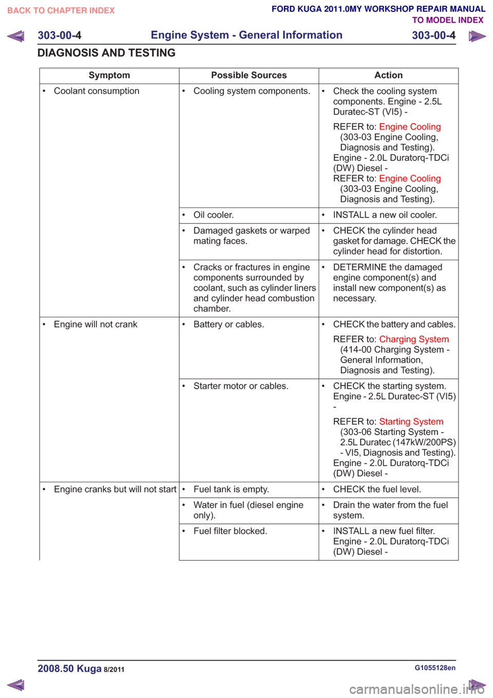
Action
Possible Sources
Symptom
• Check the cooling systemcomponents. Engine - 2.5L
Duratec-ST (VI5) -
REFER to: Engine Cooling
(303-03 Engine Cooling,
Diagnosis and Testing).
Engine - 2.0L Duratorq-TDCi
(DW) Diesel -
REFER to: Engine Cooling
(303-03 Engine Cooling,
Diagnosis and Testing).
• Cooling system components.
• Coolant consumption
• INSTALL a new oil cooler.
• Oil cooler.
• CHECK the cylinder headgasket for damage. CHECK the
cylinder head for distortion.
• Damaged gaskets or warped
mating faces.
• DETERMINE the damagedengine component(s) and
install new component(s) as
necessary.
• Cracks or fractures in engine
components surrounded by
coolant, such as cylinder liners
and cylinder head combustion
chamber.
• CHECK the battery and cables.REFER to: Charging System
(414-00 Charging System -
General Information,
Diagnosis and Testing).
• Battery or cables.
• Engine will not crank
• CHECK the starting system.Engine - 2.5L Duratec-ST (VI5)
-
REFER to: Starting System
(303-06 Starting System -
2.5L Duratec (147kW/200PS)
- VI5, Diagnosis and Testing).
Engine - 2.0L Duratorq-TDCi
(DW) Diesel -
• Starter motor or cables.
• CHECK the fuel level.
• Fuel tank is empty.
• Engine cranks but will not start
• Drain the water from the fuelsystem.
• Water in fuel (diesel engine
only).
• INSTALL a new fuel filter.Engine - 2.0L Duratorq-TDCi
(DW) Diesel -
• Fuel filter blocked.
G1055128en2008.50 Kuga8/2011
303-00-
4
Engine System - General Information
303-00- 4
DIAGNOSIS AND TESTING
TO MODEL INDEX
BACK TO CHAPTER INDEX
FORD KUGA 2011.0MY WORKSHOP REPAIR MANUAL
Page 1549 of 2057
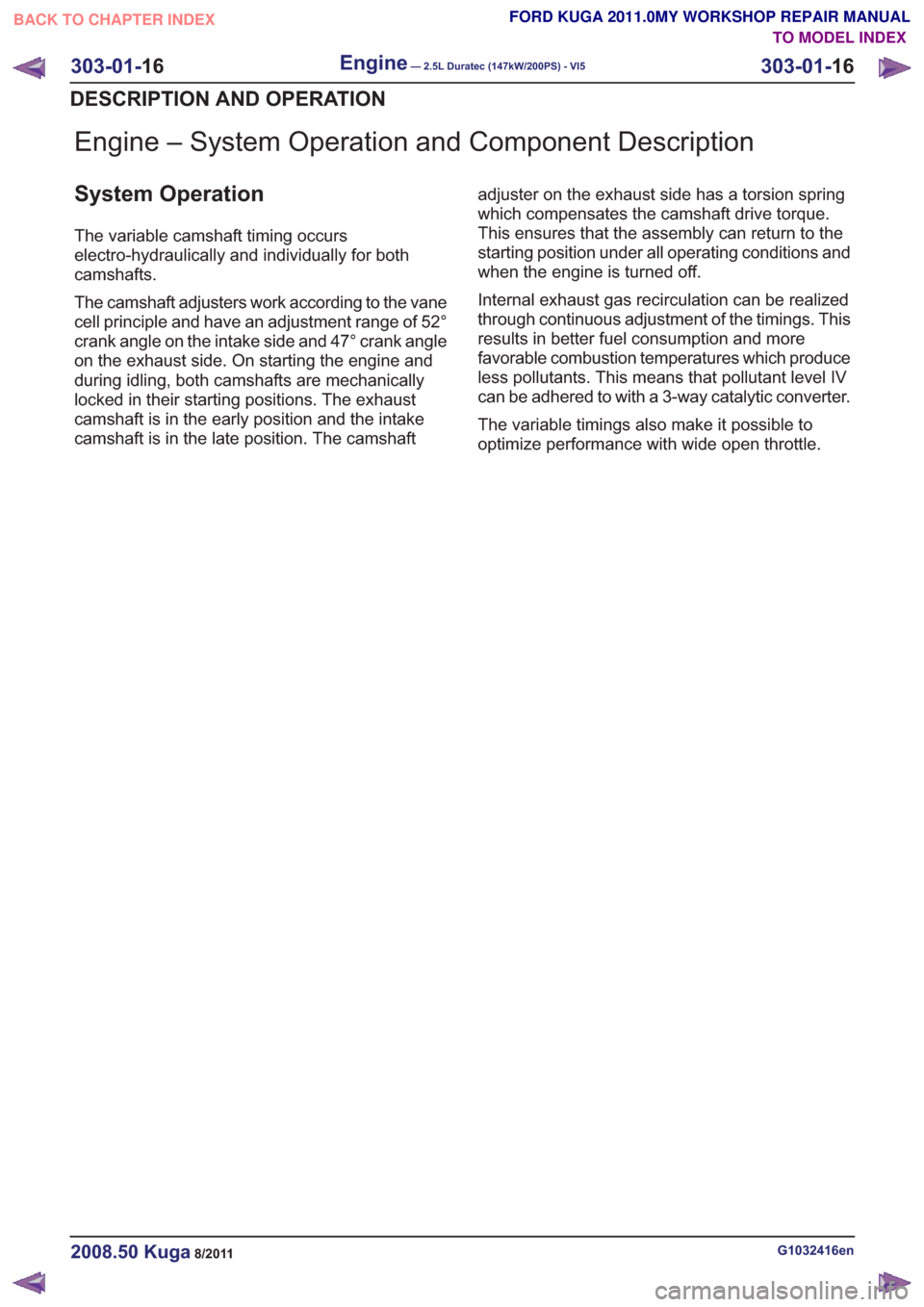
Engine – System Operation and Component Description
System Operation
The variable camshaft timing occurs
electro-hydraulically and individually for both
camshafts.
The camshaft adjusters work according to the vane
cell principle and have an adjustment range of 52°
crank angle on the intake side and 47° crank angle
on the exhaust side. On starting the engine and
during idling, both camshafts are mechanically
locked in their starting positions. The exhaust
camshaft is in the early position and the intake
camshaft is in the late position. The camshaftadjuster on the exhaust side has a torsion spring
which compensates the camshaft drive torque.
This ensures that the assembly can return to the
starting position under all operating conditions and
when the engine is turned off.
Internal exhaust gas recirculation can be realized
through continuous adjustment of the timings. This
results in better fuel consumption and more
favorable combustion temperatures which produce
less pollutants. This means that pollutant level IV
can be adhered to with a 3-way catalytic converter.
The variable timings also make it possible to
optimize performance with wide open throttle.
G1032416en2008.50 Kuga8/2011
303-01-
16
Engine— 2.5L Duratec (147kW/200PS) - VI5303-01-
16
DESCRIPTION AND OPERATION
TO MODEL INDEX
BACK TO CHAPTER INDEX
FORD KUGA 2011.0MY WORKSHOP REPAIR MANUAL
Page 1569 of 2057
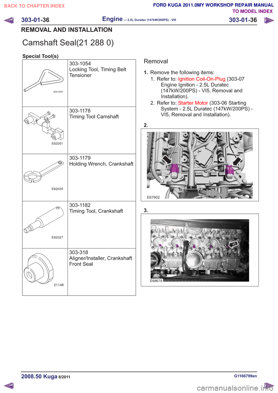
Camshaft Seal(21 288 0)
Special Tool(s)303-1054
Locking Tool, Timing Belt
Tensioner
3031054
303-1178
Timing Tool Camshaft
E62051
303-1179
Holding Wrench, Crankshaft
E62035
303-1182
Timing Tool, Crankshaft
E62027
303-318
Aligner/Installer, Crankshaft
Front Seal
21148
Removal
1.Remove the following items:
1. Refer to: Ignition Coil-On-Plug (303-07
Engine Ignition - 2.5L Duratec
(147kW/200PS) - VI5, Removal and
Installation).
2. Refer to: Starter Motor (303-06 Starting
System - 2.5L Duratec (147kW/200PS) -
VI5, Removal and Installation).
2.
E67902
3.
E68679
x5
G1166799en2008.50 Kuga8/2011
303-01- 36
Engine— 2.5L Duratec (147kW/200PS) - VI5303-01-
36
REMOVAL AND INSTALLATION
TO MODEL INDEX
BACK TO CHAPTER INDEX
FORD KUGA 2011.0MY WORKSHOP REPAIR MANUAL
Page 1577 of 2057
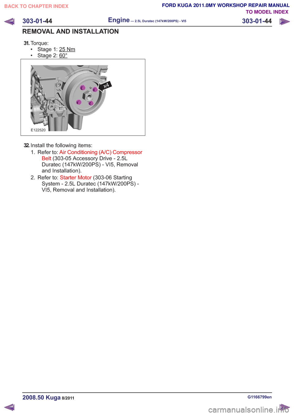
31.Torque:
• Stage 1: 25
Nm
• Stage 2: 60°
E122520
x4
32.Install the following items:
1. Refer to: Air Conditioning (A/C) Compressor
Belt (303-05 Accessory Drive - 2.5L
Duratec (147kW/200PS) - VI5, Removal
and Installation).
2. Refer to: Starter Motor (303-06 Starting
System - 2.5L Duratec (147kW/200PS) -
VI5, Removal and Installation).
G1166799en2008.50 Kuga8/2011
303-01- 44
Engine— 2.5L Duratec (147kW/200PS) - VI5303-01-
44
REMOVAL AND INSTALLATION
TO MODEL INDEX
BACK TO CHAPTER INDEX
FORD KUGA 2011.0MY WORKSHOP REPAIR MANUAL
Page 1695 of 2057
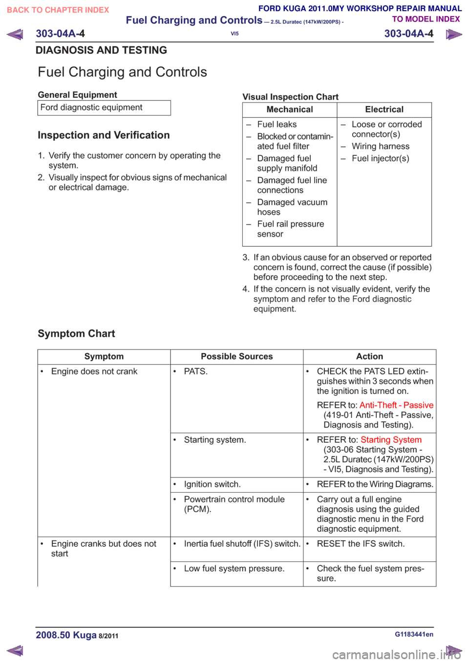
Fuel Charging and Controls
General EquipmentFord diagnostic equipment
Inspection and Verification
1. Verify the customer concern by operating the system.
2. Visually inspect for obvious signs of mechanical or electrical damage. Visual Inspection Chart
Electrical
Mechanical
– Loose or corrodedconnector(s)
– Wiring harness
– Fuel injector(s)
– Fuel leaks
– Blocked or contamin-
ated fuel filter
– Damaged fuel supply manifold
– Damaged fuel line connections
– Damaged vacuum hoses
– Fuel rail pressure sensor
3. If an obvious cause for an observed or reported concern is found, correct the cause (if possible)
before proceeding to the next step.
4. If the concern is not visually evident, verify the symptom and refer to the Ford diagnostic
equipment .
Symptom Chart
Action
Possible Sources
Symptom
• CHECK the PATS LED extin-guishes within 3 seconds when
the ignition is turned on.
REFER to: Anti-Theft - Passive
(419-01 Anti-Theft - Passive,
Diagnosis and Testing).
• PAT S .
• Engine does not crank
• REFER to:Starting System
(303-06 Starting System -
2.5L Duratec (147kW/200PS)
- VI5, Diagnosis and Testing).
• Starting system.
• REFER to the Wiring Diagrams.
• Ignition switch.
• Carry out a full enginediagnosis using the guided
diagnostic menu in the Ford
diagnostic equipment.
• Powertrain control module
(PCM).
• RESET the IFS switch.
• Inertia fuel shutoff (IFS) switch.
• Engine cranks but does not
start
• Check the fuel system pres-sure.
• Low fuel system pressure.
G1183441en2008.50 Kuga8/2011
303-04A-
4
Fuel Charging and Controls
— 2.5L Duratec (147kW/200PS) -
VI5
303-04A- 4
DIAGNOSIS AND TESTING
TO MODEL INDEX
BACK TO CHAPTER INDEX
FORD KUGA 2011.0MY WORKSHOP REPAIR MANUAL
Page 1697 of 2057
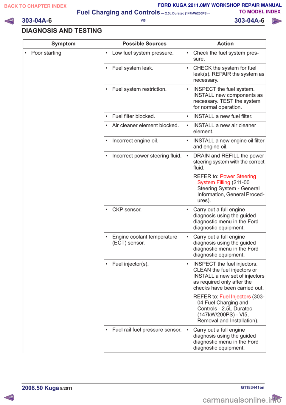
Action
Possible Sources
Symptom
• Check the fuel system pres-sure.
• Low fuel system pressure.
• Poor starting
• CHECK the system for fuelleak(s). REPAIR the system as
necessary.
• Fuel system leak.
• INSPECT the fuel system.INSTALL new components as
necessary. TEST the system
for normal operation.
• Fuel system restriction.
• INSTALL a new fuel filter.
• Fuel filter blocked.
• INSTALL a new air cleanerelement.
• Air cleaner element blocked.
• INSTALL a new engine oil filterand engine oil.
• Incorrect engine oil.
• DRAIN and REFILL the powersteering system with the correct
fluid.
REFER to: Power Steering
System Filling (211-00
Steering System - General
Information, General Proced-
ures).
• Incorrect power steering fluid.
• Carry out a full enginediagnosis using the guided
diagnostic menu in the Ford
diagnostic equipment.
• CKP sensor.
• Carry out a full enginediagnosis using the guided
diagnostic menu in the Ford
diagnostic equipment.
• Engine coolant temperature
(ECT) sensor.
• INSPECT the fuel injectors.CLEAN the fuel injectors or
INSTALL a new set of injectors
as required only after the
checks have been carried out.
REFER to: Fuel Injectors (303-
04 Fuel Charging and
Controls - 2.5L Duratec
(147kW/200PS) - VI5,
Removal and Installation).
• Fuel injector(s).
• Carry out a full enginediagnosis using the guided
diagnostic menu in the Ford
diagnostic equipment.
• Fuel rail fuel pressure sensor.
G1183441en2008.50 Kuga8/2011
303-04A-
6
Fuel Charging and Controls
— 2.5L Duratec (147kW/200PS) -
VI5
303-04A- 6
DIAGNOSIS AND TESTING
TO MODEL INDEX
BACK TO CHAPTER INDEX
FORD KUGA 2011.0MY WORKSHOP REPAIR MANUAL
Page 1745 of 2057
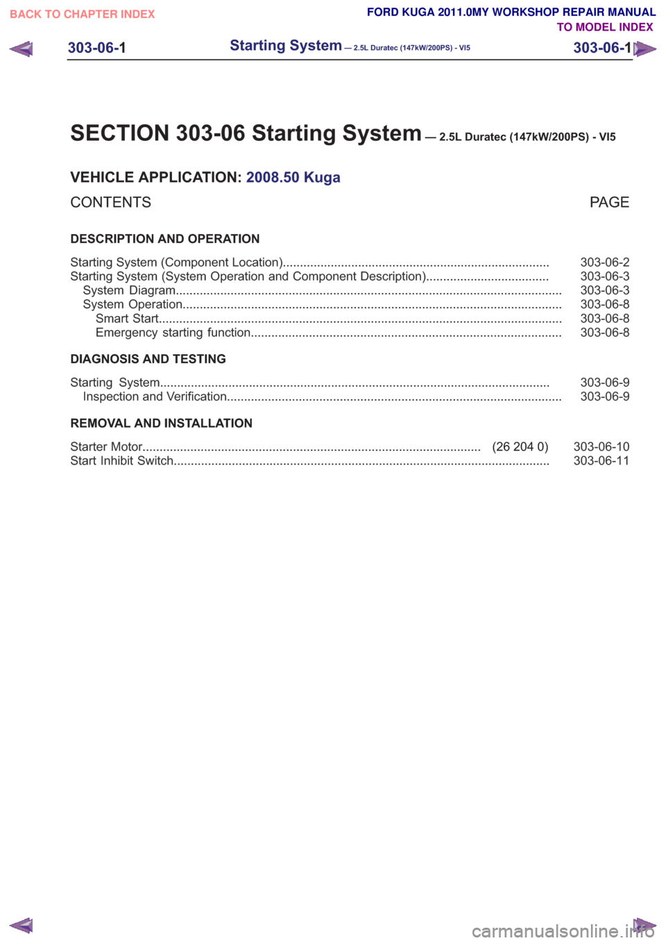
SECTION 303-06 Starting System— 2.5L Duratec (147kW/200PS) - VI5
VEHICLE APPLICATION:2008.50 Kuga
PA G E
CONTENTS
DESCRIPTION AND OPERATION
303-06-2
Starting System (Component Location) ........................................................................\
......
303-06-3
Starting System (System Operation and Component Description) ....................................
303-06-3
System Diagram ........................................................................\
.........................................
303-06-8
System Operation ........................................................................\
.......................................
303-06-8
Smart Start ........................................................................\
..............................................
303-06-8
Emergency starting function ........................................................................\
...................
DIAGNOSIS AND TESTING 303-06-9
Starting System ........................................................................\
..........................................
303-06-9
Inspection and Verification ........................................................................\
..........................
REMOVAL AND INSTALLATION 303-06-10
(26 204 0)
Starter Motor ........................................................................\
...........................
303-06-11
Start Inhibit Switch ........................................................................\
......................................
303-06-1
Starting System— 2.5L Duratec (147kW/200PS) - VI5303-06-
1
.
TO MODEL INDEX
BACK TO CHAPTER INDEX
FORD KUGA 2011.0MY WORKSHOP REPAIR MANUAL