2011 FORD KUGA CD changer
[x] Cancel search: CD changerPage 383 of 2057

Description
Item
Medium speed CAN (controller area
network) bus (MS-CAN)
A
High speed CAN bus (HS-CAN)
B
LIN (local interconnect network) bus
C
Terminating resistors
Drive
DLC (data link connector)
E
GEMRefer to Component Description: ABS
(page ?)
1
Fuel fired booster heater /programmable
fuel fired booster heater
2
The EATC control module
3
Reversing camera module (RVC)
4
Parking aid module (PAM)
5
DDM6
Front driver's side switch unit
7
Driver's side RDM
8
PDM (Passenger Door Module)
9
Passenger side RDM
10
Audio unit/navigation unit
11
CD changer
12 Description
Item
Navigation system module - vehicles
equipped with DVD navigation system with
touch screen (not communicating with the
diagnostic unit)
13
Navigation system display - vehicles
equipped with DVD navigation system with
touch screen (not communicating with the
diagnostic unit)
14
Control module for electronic auxiliary
equipment (BVC)
15
RCM16
Keyless vehicle module (KVM)
17
Instrument Cluster
18
PCM19
Fuel additive system module.
20
ABS module or electronic stability program
module
21
Yaw rate sensor/lateral acceleration
sensor
22
Headlamp Leveling Module
23
All-wheel drive control unit
24
Electrohydraulic power steering module
25
System Operation
General
In a communications network (data bus system),
various modules of different systems are connected
to one another via one or several lines.
The data bus system is used exclusively for
transmitting data between the connected modules,
as well as between the connected modules and
the Ford diagnostic unit.
In a data bus system, complete data blocks are
transmitted instead of single on/off pulses. In
addition to the actual information, these data blocks
also contain data regarding the address of the
module to be addressed, the size of the data block
and information for monitoring the content of each
individual data block.
Data bus systems offer various advantages: • Simplified data transmission between the
modules due to a standardized protocol
• Fewer sensors and connectors
• Improved diagnostic options
• Lower costs
The DLC is connected to the various data bus
systems and to the power supply via the standard
16-pin GEM. The signal for the module
programming is also transferred via the DLC.
In a data bus system, if there is a break in one or
both lines or there is a short to ground or to voltage,
then communication between the modules and
with the Ford diagnostic unit is disturbed or is no
longer possible at all.
In order to be able to establish communication with
one another, the modules of the individual systems G1030779en
2008.50 Kuga 8/2011 418-00-6
Module Communications Network
418-00-6
DESCRIPTION AND OPERATIONTO MODEL INDEX
BACK TO CHAPTER INDEX
FORD KUGA 2011.0MY WORKSHOP REPAIR MANUAL
Page 1674 of 2057
Engine Cooling — 2.5L Duratec (147kW/200PS) - VI5 – Overview
Auxiliary coolant pump
An electrically operated auxiliary coolant pump is
installed on vehicles with a trailer coupling and/or
additional heating. The auxiliary coolant pump
ensures that the coolant is circulated when the
coolant pump (which is driven by the engine) is not
running.
The additional heating uses the auxiliary coolant
pump to circulate hot coolant through the heat
exchanger and the engine.
On vehicles with a trailer coupling the auxiliary
coolant pump is switched on for 6 minutes by the
PCM (powertrain control module) if the coolant
temperature exceeds 106°C when the engine is
switched off. This prevents the coolant circuit from
overheating. This could happen particularly if the
engine is switched off after towing a heavy trailer
up a steep hill before there has been sufficient time
for cooling.
G1088220en2008.50 Kuga8/2011
303-03-3
Engine Cooling
303-03- 3
DESCRIPTION AND OPERATION
TO MODEL INDEX
BACK TO CHAPTER INDEX
FORD KUGA 2011.0MY WORKSHOP REPAIR MANUAL
Page 1829 of 2057
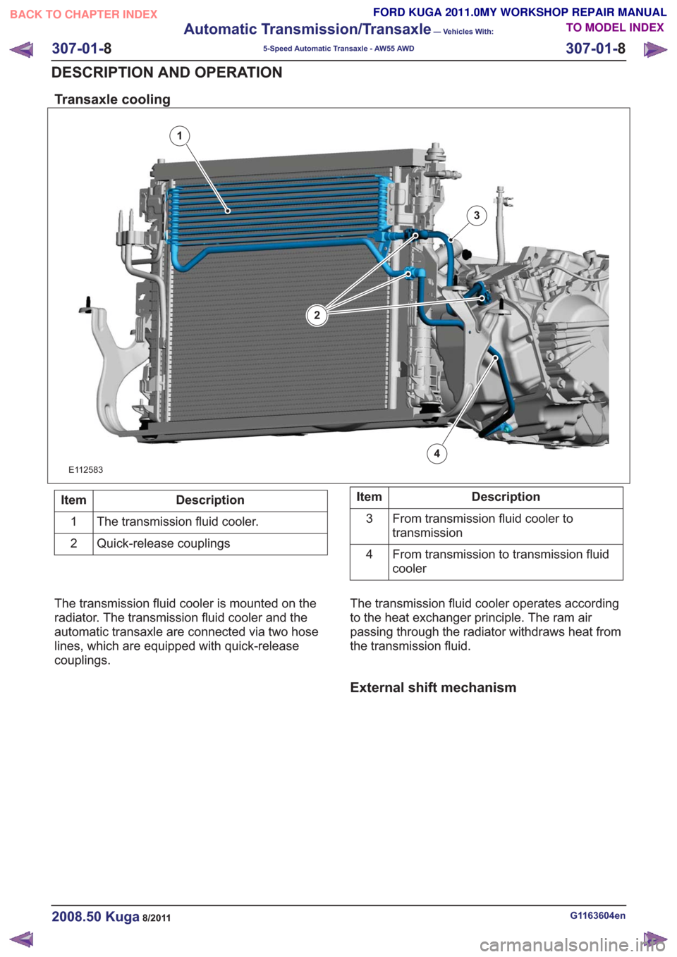
Transaxle cooling
1
2
3
4
E112583
Description
Item
The transmission fluid cooler.
1
Quick-release couplings
2Description
Item
From transmission fluid cooler to
transmission
3
From transmission to transmission fluid
cooler
4
The transmission fluid cooler is mounted on the
radiator. The transmission fluid cooler and the
automatic transaxle are connected via two hose
lines, which are equipped with quick-release
couplings. The transmission fluid cooler operates according
to the heat exchanger principle. The ram air
passing through the radiator withdraws heat from
the transmission fluid.
External shift mechanism
G1163604en2008.50 Kuga8/2011
307-01-
8
Automatic Transmission/Transaxle
— Vehicles With:
5-Speed Automatic Transaxle - AW55 AWD
307-01- 8
DESCRIPTION AND OPERATION
TO MODEL INDEX
BACK TO CHAPTER INDEX
FORD KUGA 2011.0MY WORKSHOP REPAIR MANUAL
Page 1924 of 2057
Transmission Cooling – Overview
Overview
The transmission fluid cooler is secured on the
radiator.
The transmission fluid cooler operates according
to the heat exchanger principle. The ram air
passing through the radiator withdraws heat from
the transmission fluid.
G1163664en2008.50 Kuga8/2011
307-02-3
Transmission/Transaxle Cooling
— Vehicles With: 5-Speed
Automatic Transaxle - AW55 AWD/6-Speed Automatic Transaxle - 6DCT450
307-02- 3
DESCRIPTION AND OPERATION
TO MODEL INDEX
BACK TO CHAPTER INDEX
FORD KUGA 2011.0MY WORKSHOP REPAIR MANUAL
Page 2028 of 2057
SECTION 412-01 Climate Control
VEHICLE APPLICATION:2008.50 Kuga
PA G E
CONTENTS
SPECIFICATIONS
412-01-3
Specifications ........................................................................\
..............................................
DESCRIPTION AND OPERATION 412-01-4
Climate Control (Component Location) ........................................................................\
......
412-01-10
Climate Control (Overview) ........................................................................\
........................
412-01-10
Pollen filter ........................................................................\
..................................................
412-01-10
Heat exchanger ........................................................................\
..........................................
412-01-10
Evaporator assembly ........................................................................\
..................................
412-01-10
Blower motor ........................................................................\
..............................................
412-01-11
Fault Memory Interrogation without diagnostics unit - vehicles with automatic temperature
control ........................................................................\
.......................................................
412-01-11
Switch over from Celsius to Fahrenheit ........................................................................\
......
412-01-12
Climate Control (System Operation and Component Description) .....................................
412-01-12
System Diagram ........................................................................\
.........................................
412-01-19
System Operation ........................................................................\
.......................................
412-01-19
Climate control housing ........................................................................\
..........................
412-01-22
Climate control ........................................................................\
........................................
412-01-24
Component Description ........................................................................\
..............................
412-01-24
Air conditioning compressor ........................................................................\
...................
412-01-24
Pollen filter ........................................................................\
..............................................
412-01-24
Control assembly, climate control - vehicles with manual temperature control ..............
412-01-25
Control assembly, climate control - vehicles with automatic temperature control ...........
412-01-25
Control assembly, climate control - vehicles with DVD navigation system with a touch
screen........................................................................\
................................................... 412-01-25
Climate control module - vehicles with DVD navigation system with a touch screen.....
412-01-25
Sun sensor - vehicles with automatic temperature control .............................................
412-01-26
In-vehicle temperature sensor ........................................................................\
................
412-01-26
Ambient temperature sensor ........................................................................\
..................
412-01-26
Blower motor ........................................................................\
...........................................
412-01-26
Blower control module - vehicles equipped with automatic temperature control ............
REMOVAL AND INSTALLATION 412-01-28
(34 626 4)
Air Conditioning (A/C) Compressor — 2.5L Duratec (147kW/200PS) - VI5 ....
412-01-29
Air Conditioning (A/C) Compressor to Condenser Discharge Line .....................................
412-01-30
Air Conditioning (A/C) Compressor to Condenser Discharge Line — 2.5L Duratec
(147kW/200PS) - VI5 ........................................................................\
................................
412-01-31
Condenser ........................................................................\
..................................................
412-01-35
Clutch and Clutch Field Coil........................................................................\
.......................
412-01-36
Pollen Filter — RHD........................................................................\
...................................
412-01-37
(34
374 0)
Blower Motor — RHD ........................................................................\
.............
412-01-40
(34 382 0)
Blower Motor Resistor — Vehicles With: Manual Temperature Control, RHD .
412-01-41
(34 382 0)
Blower Motor Resistor — Vehicles With: Dual Automatic Temperature
Control ........................................................................\
..................................
412-01- 1
Climate Control
412-01- 1
.
TO MODEL INDEX
BACK TO CHAPTER INDEX
PAGE 1 OF 2 FORD KUGA 2011.0MY WORKSHOP REPAIR MANUAL
Page 2037 of 2057
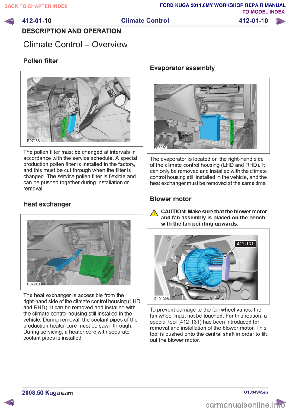
Climate Control – Overview
Pollen filter
E97258
The pollen filter must be changed at intervals in
accordance with the service schedule. A special
production pollen filter is installed in the factory,
and this must be cut through when the filter is
changed. The service pollen filter is flexible and
can be pushed together during installation or
removal.
Heat exchanger
E97249
The heat exchanger is accessible from the
right-hand side of the climate control housing (LHD
and RHD). It can be removed and installed with
the climate control housing still installed in the
vehicle. During removal, the coolant pipes of the
production heater core must be sawn through.
During servicing, a heater core with separate
coolant pipes is installed.
Evaporator assembly
E97250
The evaporator is located on the right-hand side
of the climate control housing (LHD and RHD). It
can only be removed and installed with the climate
control housing still installed in the vehicle, and the
heat exchanger must be removed at the same time.
Blower motor
CAUTION: Make sure that the blower motor
and fan assembly is placed on the bench
with the fan pointing upwards.
412-131
E101398
To prevent damage to the fan wheel vanes, the
fan wheel must not be touched. For this reason, a
special tool (412-131) has been introduced for
removal and installation of the blower motor. This
tool is pushed onto the central shaft in order to lift
out the blower motor.
G1034945en2008.50 Kuga8/2011
412-01-10
Climate Control
412-01- 10
DESCRIPTION AND OPERATION
TO MODEL INDEX
BACK TO CHAPTER INDEX
FORD KUGA 2011.0MY WORKSHOP REPAIR MANUAL
Page 2047 of 2057
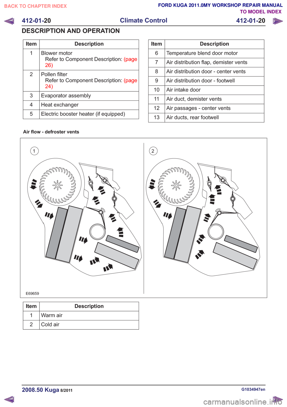
Description
Item
Blower motorRefertoComponentDescription:(page
26)
1
Pollen filterRefertoComponentDescription:(page
24)
2
Evaporator assembly
3
Heat exchanger
4
Electric booster heater (if equipped)
5Description
Item
Temperature blend door motor
6
Air distribution flap, demister vents
7
Air distribution door - center vents
8
Air distribution door - footwell
9
Air intake door
10
Air duct, demister vents
11
Air passages - center vents
12
Air ducts, rear footwell
13
Air flow - defroster vents
12
E69659
Description
Item
Warm air
1
Cold air
2
G1034947en2008.50 Kuga8/2011
412-01- 20
Climate Control
412-01- 20
DESCRIPTION AND OPERATION
TO MODEL INDEX
BACK TO CHAPTER INDEX
FORD KUGA 2011.0MY WORKSHOP REPAIR MANUAL