2011 FORD KUGA ECO mode
[x] Cancel search: ECO modePage 1735 of 2057
Pilling
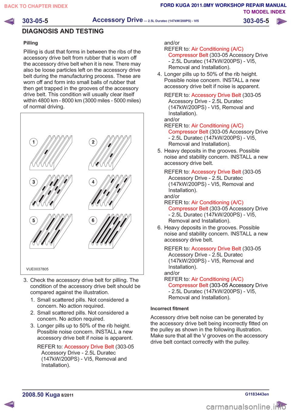
Pilling is dust that forms in between the ribs of the
accessory drive belt from rubber that is worn off
the accessory drive belt when it is new. There may
also be loose particles left on the accessory drive
belt during the manufacturing process. These are
worn off and form into small balls of rubber that
then get trapped in the grooves of the accessory
drive belt. This condition will usually clear itself
within 4800 km - 8000 km (3000 miles - 5000 miles)
of normal driving.
VUE0037805
3. Check the accessory drive belt for pilling. Thecondition of the accessory drive belt should be
compared against the illustration.
1. Small scattered pills. Not considered a concern. No action required.
2. Small scattered pills. Not considered a concern. No action required.
3. Longer pills up to 50% of the rib height. Possible noise concern. INSTALL a new
accessory drive belt if noise is apparent.
REFER to: Accessory Drive Belt (303-05
Accessory Drive - 2.5L Duratec
(147kW/200PS) - VI5, Removal and
Installation). and/or
REFER to:
Air Conditioning (A/C)
Compressor Belt (303-05 Accessory Drive
- 2.5L Duratec (147kW/200PS) - VI5,
Removal and Installation).
4. Longer pills up to 50% of the rib height. Possible noise concern. INSTALL a new
accessory drive belt if noise is apparent.
REFER to: Accessory Drive Belt (303-05
Accessory Drive - 2.5L Duratec
(147kW/200PS) - VI5, Removal and
Installation).
and/or
REFER to: Air Conditioning (A/C)
Compressor Belt (303-05 Accessory Drive
- 2.5L Duratec (147kW/200PS) - VI5,
Removal and Installation).
5. Heavy deposits in the grooves. Possible noise and stability concern. INSTALL a new
accessory drive belt.
REFER to: Accessory Drive Belt (303-05
Accessory Drive - 2.5L Duratec
(147kW/200PS) - VI5, Removal and
Installation).
and/or
REFER to: Air Conditioning (A/C)
Compressor Belt (303-05 Accessory Drive
- 2.5L Duratec (147kW/200PS) - VI5,
Removal and Installation).
6. Heavy deposits in the grooves. Possible noise and stability concern. INSTALL a new
accessory drive belt.
REFER to: Accessory Drive Belt (303-05
Accessory Drive - 2.5L Duratec
(147kW/200PS) - VI5, Removal and
Installation).
and/or
REFER to: Air Conditioning (A/C)
Compressor Belt (303-05 AccessoryDrive
- 2.5L Duratec (147kW/200PS) - VI5,
Removal and Installation).
Incorrect fitment
Accessory drive belt noise can be generated by
the accessory drive belt being incorrectly fitted on
the pulley as shown in the following illustration.
Make sure that all the V grooves on the accessory
drive belt contact correctly with the pulley.
G1183443en2008.50 Kuga8/2011
303-05- 5
Accessory Drive— 2.5L Duratec (147kW/200PS) - VI5303-05-
5
DIAGNOSIS AND TESTING
TO MODEL INDEX
BACK TO CHAPTER INDEX
FORD KUGA 2011.0MY WORKSHOP REPAIR MANUAL
Page 1752 of 2057
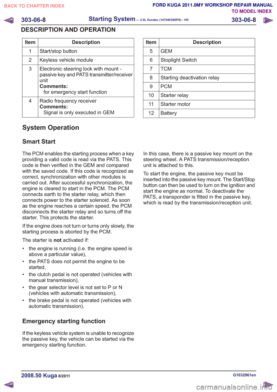
Description
Item
Start/stop button
1
Keyless vehicle module
2
Electronic steering lock with mount -
passive key and PATS transmitter/receiver
unit
Comments:for emergency start function
3
Radio frequency receiver
Comments:Signal is only executed in GEM
4Description
Item
GEM
5
Stoplight Switch
6
TCM7
Starting deactivation relay
8
PCM
9
Starter relay
10
Starter motor
11
Battery
12
System Operation
Smart Start
The PCM enables the starting process when a key
providing a valid code is read via the PATS. This
code is then verified in the GEM and compared
with the saved code. If this code is recognized as
correct, synchronization with other modules is
carried out. After successful synchronization, the
engine is cleared to start in the PCM. The PCM
connects earth to the starter relay, which then
connects power to the starter solenoid. As soon
as the engine reaches a certain speed, the PCM
disconnects the starter relay and so turns off the
starter. This protects the starter.
If the engine does not turn or turns only slowly, the
starting process is aborted by the PCM.
The starter is notactivated if:
• the engine is running (i.e. the engine speed is above a particular value),
• the PATS does not permit the engine to be started,
• the clutch pedal is not operated (vehicles with manual transmission),
• the gear selector level is not set to P or N (vehicles with automatic transmission),
• the brake pedal is not operated (vehicles with automatic transmission).
Emergency starting function
If the keyless vehicle system is unable to recognize
the passive key, the vehicle can be started via the
emergency starting function. In this case, there is a passive key mount on the
steering wheel. A PATS transmission/reception
unit is attached to this.
To start the engine, the passive key must be
inserted into the passive key mount. The Start/Stop
button can then be used to turn on the ignition and
start the engine as normal. To deactivate the
PATS, a transponder is fitted in the passive key,
which is read by the transmission/reception unit.
G1032961en2008.50 Kuga8/2011
303-06-
8
Starting System— 2.5L Duratec (147kW/200PS) - VI5303-06-
8
DESCRIPTION AND OPERATION
TO MODEL INDEX
BACK TO CHAPTER INDEX
FORD KUGA 2011.0MY WORKSHOP REPAIR MANUAL
Page 1763 of 2057
Engine Emission Control
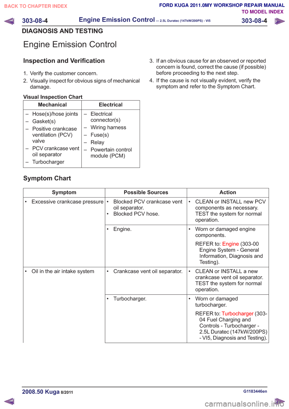
Inspection and Verification
1. Verify the customer concern.
2. Visually inspect for obvious signs of mechanicaldamage.
Visual Inspection Chart
Electrical
Mechanical
– Electricalconnector(s)
– Wiring harness
– Fuse(s)
– Relay
– Powertain control module (PCM)
– Hose(s)/hose joints
– Gasket(s)
– Positive crankcase
ventilation (PCV)
valve
– PCV crankcase vent oil separator
– Turbocharger 3. If an obvious cause for an observed or reported
concern is found, correct the cause (if possible)
before proceeding to the next step.
4. If the cause is not visually evident, verify the symptom and refer to the Symptom Chart.
Symptom Chart
Action
Possible Sources
Symptom
• CLEAN or INSTALL new PCVcomponents as necessary.
TEST the system for normal
operation.
• Blocked PCV crankcase vent
oil separator.
• Blocked PCV hose.
• Excessive crankcase pressure
• Worn or damaged enginecomponents.
REFER to: Engine(303-00
Engine System - General
Information, Diagnosis and
Testing).
• Engine.
• CLEAN or INSTALL a newcrankcase vent oil separator.
TEST the system for normal
operation.
• Crankcase vent oil separator.
• Oil in the air intake system
• Worn or damagedturbocharger.
REFER to: Turbocharger (303-
04 Fuel Charging and
Controls - Turbocharger -
2.5L Duratec (147kW/200PS)
- VI5, Diagnosis and Testing).
• Turbocharger.
G1183446en2008.50 Kuga8/2011
303-08-
4
Engine Emission Control— 2.5L Duratec (147kW/200PS) - VI5303-08-
4
DIAGNOSIS AND TESTING
TO MODEL INDEX
BACK TO CHAPTER INDEX
FORD KUGA 2011.0MY WORKSHOP REPAIR MANUAL
Page 1764 of 2057
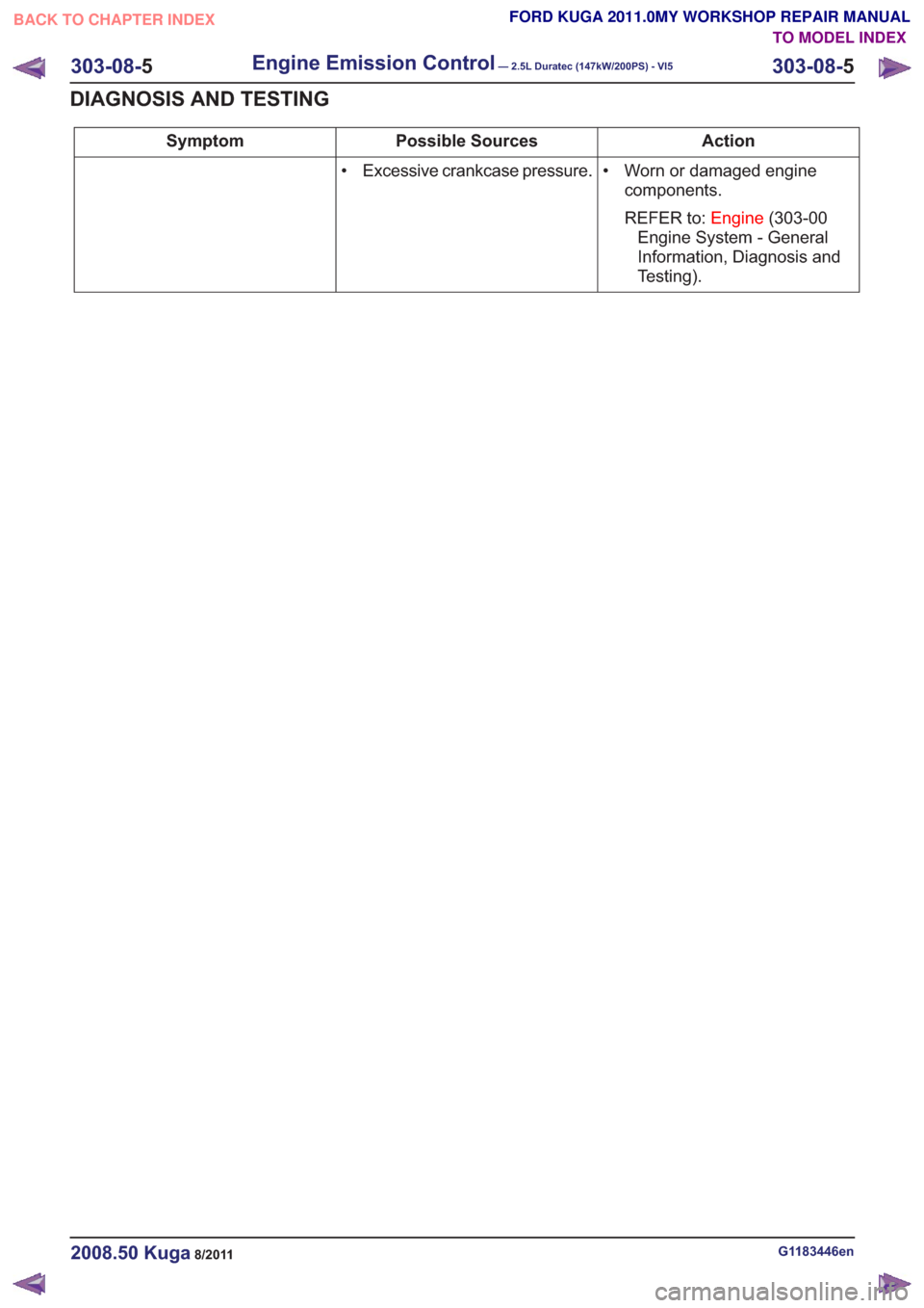
Action
Possible Sources
Symptom
• Worn or damaged enginecomponents.
REFER to: Engine(303-00
Engine System - General
Information, Diagnosis and
Testing).
• Excessive crankcase pressure.
G1183446en2008.50 Kuga8/2011
303-08-
5
Engine Emission Control— 2.5L Duratec (147kW/200PS) - VI5303-08-
5
DIAGNOSIS AND TESTING
TO MODEL INDEX
BACK TO CHAPTER INDEX
FORD KUGA 2011.0MY WORKSHOP REPAIR MANUAL
Page 1775 of 2057
SECTION 303-14 Electronic Engine Controls— 2.5L Duratec
(147kW/200PS) - VI5
VEHICLE APPLICATION: 2008.50 Kuga
PA G E
CONTENTS
DESCRIPTION AND OPERATION
303-14-3
Electronic Engine Controls (Component Location) .............................................................
303-14-7
Electronic Engine Controls (Overview) ........................................................................\
.......
303-14-7
General overview ........................................................................\
........................................
303-14-8
Powertrain Control Module (PCM) ........................................................................\
..............
303-14-8
Knock Sensor ........................................................................\
.............................................
303-14-8
Camshaft Position (CMP) Sensor ........................................................................\
...............
303-14-9
Crankshaft Position (CKP) sensor ........................................................................\
..............
303-14-9
Camshaft adjuster solenoid valve........................................................................\
...............
303-14-9
Manifold absolute pressure and temperature sensor .........................................................
303-14-9
Accelerator pedal position (APP) sensor ........................................................................\
....
303-14-10
Throttle control unit ........................................................................\
.....................................
303-14-10
Engine Coolant Temperature (ECT) sensor.......................................................................
303-14-10
Ignition coil-on-plug ........................................................................\
....................................
303-14-12
Electronic Engine Controls (System Operation and Component Description) ...................
303-14-12
System Diagram ........................................................................\
.........................................
303-14-16
System Operation ........................................................................\
.......................................
303-14-18
Speed and TDC recording ........................................................................\
......................
303-14-19
Calculation of the ignition angle ........................................................................\
..............
303-14-20
Engine fueling ........................................................................\
.........................................
303-14-22
Engine speed control ........................................................................\
..............................
303-14-22
Oil monitoring ........................................................................\
..........................................
303-14-23
Calculation of valve timing adjustment angle..................................................................
303-14-23
Boost pressure control ........................................................................\
............................
303-14-24
Starting process ........................................................................\
......................................
303-14-24
Alternator control (Smart Charge) ........................................................................\
...........
303-14-24
Component Description ........................................................................\
..............................
303-14-24
CKP sensor ........................................................................\
.............................................
303-14-25
Broadband HO2S ........................................................................\
...................................
303-14-26
VCT (variable camshaft timing) solenoids ......................................................................
303-14-27
MAF sensor ........................................................................\
.............................................
303-14-28
APP sensor ........................................................................\
.............................................
303-14-29
CPP sensor ........................................................................\
.............................................
303-14-29
BPP switches ........................................................................\
..........................................
303-14-30
Air conditioning (A/C) pressure sensor ........................................................................\
...
303-14-30
Throttle
control unit ........................................................................\
.................................
303-14-31
ECT sensor ........................................................................\
.............................................
303-14-31
Cooling fan module ........................................................................\
.................................
303-14-32
injectors........................................................................\
...................................................
303-14-32
Ignition coil-on-plug ........................................................................\
.................................
303-14-33
Fuel pressure/fuel temperature sensor ........................................................................\
...
303-14-33
Wastegate control valve ........................................................................\
..........................
303-14-34
Engine oil level, temperature and quality sensor ............................................................
303-14-1
Electronic Engine Controls— 2.5L Duratec (147kW/200PS) - VI5303-14-
1
.
TO MODEL INDEX
BACK TO CHAPTER INDEX
PAGE 1 OF 2
FORD KUGA 2011.0MY WORKSHOP REPAIR MANUAL
Page 1784 of 2057
If one of the two APP sensors fails, then only a
proportion of the engine's power will be available
when accelerating. Top speed can nevertheless
be achieved.
If both of the APP sensors fail, the engine is
regulated to a defined speed following a plausibility
check after the BPP (brake pedal position) switch
and brake light switch have been actuated once.
The vehicle can then only be accelerated to a
defined speed.
In either case, a fault is saved in the error memory
of the PCM.
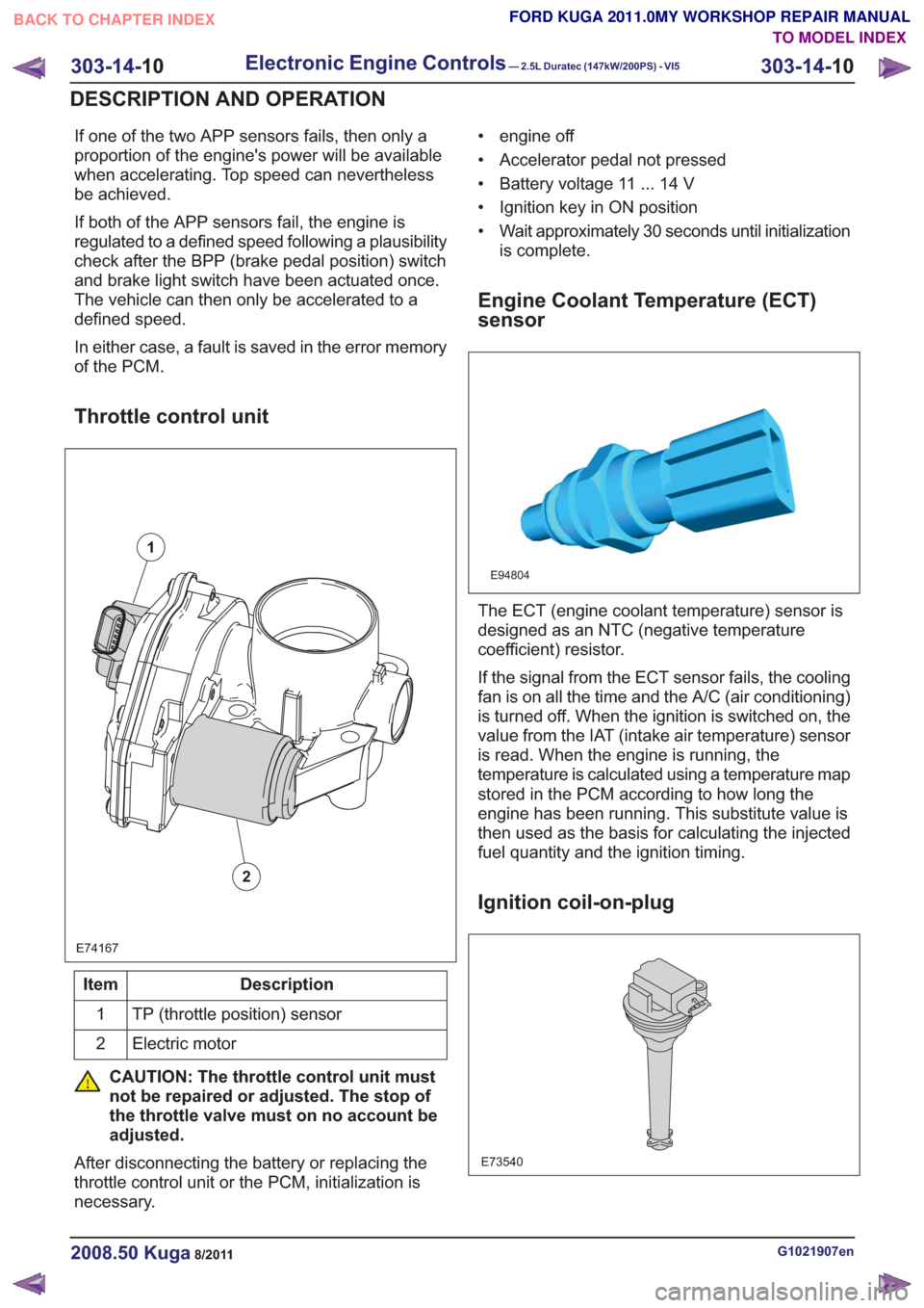
Throttle control unit
E74167
1
2
Description
Item
TP (throttle position) sensor
1
Electric motor
2
CAUTION: The throttle control unit must
not be repaired or adjusted. The stop of
the throttle valve must on no account be
adjusted.
After disconnecting the battery or replacing the
throttle control unit or the PCM, initialization is
necessary. • engine off
• Accelerator pedal not pressed
• Battery voltage 11 ... 14 V
• Ignition key in ON position
• Wait approximately 30 seconds until initialization
is complete.
Engine Coolant Temperature (ECT)
sensor
E94804
The ECT (engine coolant temperature) sensor is
designed as an NTC (negative temperature
coefficient) resistor.
If the signal from the ECT sensor fails, the cooling
fan is on all the time and the A/C (air conditioning)
is turned off. When the ignition is switched on, the
value from the IAT (intake air temperature) sensor
is read. When the engine is running, the
temperature is calculated using a temperature map
stored in the PCM according to how long the
engine has been running. This substitute value is
then used as the basis for calculating the injected
fuel quantity and the ignition timing.
Ignition coil-on-plug
E73540
G1021907en2008.50 Kuga8/2011
303-14- 10
Electronic Engine Controls— 2.5L Duratec (147kW/200PS) - VI5303-14-
10
DESCRIPTION AND OPERATION
TO MODEL INDEX
BACK TO CHAPTER INDEX
FORD KUGA 2011.0MY WORKSHOP REPAIR MANUAL
Page 1792 of 2057
• Torque reduction request (stability assistmodule)
• Cruise control request
The PCM sends the following signals via the CAN
databus:
• Fuel pump relay on/off
• Engine speed
• Warning lights on/off (MIL (malfunction indicator lamp), battery warning lamp)
• PAT S
•ECT
• Air conditioning pressure transducer
• Outside air temperature
With the aid of the input and output signals listed
above, the PCM controls / regulates engine
starting, fuel injection and fuel pressure, ignition,
boost pressure, camshaft adjustment, tank purging,
the radiator fan and the refrigerant compressor.
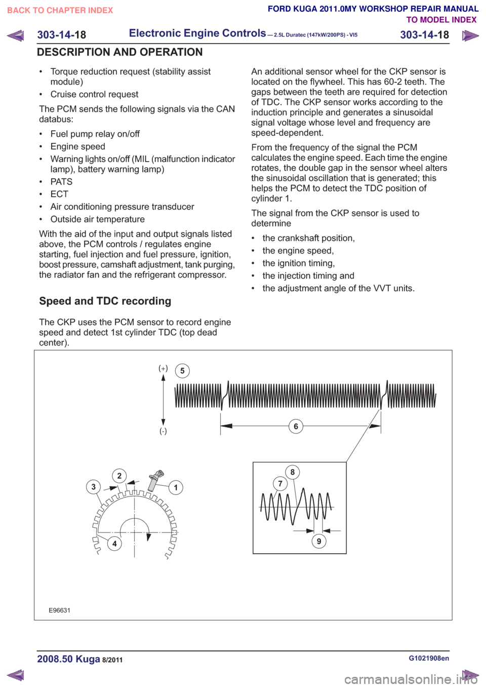
Speed and TDC recording
The CKP uses the PCM sensor to record engine
speed and detect 1st cylinder TDC (top dead
center). An additional sensor wheel for the CKP sensor is
located on the flywheel. This has 60-2 teeth. The
gaps between the teeth are required for detection
of TDC. The CKP sensor works according to the
induction principle and generates a sinusoidal
signal voltage whose level and frequency are
speed-dependent.
From the frequency of the signal the PCM
calculates the engine speed. Each time the engine
rotates, the double gap in the sensor wheel alters
the sinusoidal oscillation that is generated; this
helps the PCM to detect the TDC position of
cylinder 1.
The signal from the CKP sensor is used to
determine
• the crankshaft position,
• the engine speed,
• the ignition timing,
• the injection timing and
• the adjustment angle of the VVT units.
2
3
4
1
9
7
8
6
5
2
3
4
1
9
7
8
6
5
E96631
G1021908en2008.50 Kuga8/2011
303-14-
18
Electronic Engine Controls— 2.5L Duratec (147kW/200PS) - VI5303-14-
18
DESCRIPTION AND OPERATION
TO MODEL INDEX
BACK TO CHAPTER INDEX
FORD KUGA 2011.0MY WORKSHOP REPAIR MANUAL
Page 1795 of 2057
actuated) or opened (actuated). Each cylinder has
its own injector. The injection is accurately dosed
and takes place at a time determined by the PCM.
Injection takes place immediately in front of the
intake valves of the cylinder. The injectors are
actuated ground side via end-stages integrated
into the PCM and using the signal calculated by
the engine management system. Power is supplied
via the Powertrain Control Module relay in the BJB.
The injected fuel quantity depends on the opening
time, the fuel pressure and the diameter of the
nozzle holes.
The fuel metering is determined via open or
closed-loop control.
The open control loop differs from the closed
control loop in that the lambda control is
deactivated.
The PCM switches from closed to open-loop control
if the HO2S cools down to below 600°C or fails, as
well as when accelerating, coasting and at full load.
Regulation of injected fuel quantity via the PCM
involves:
• controlling the fuel pump,
• calculating the required quantity of fuel forengine starting,
• observance of the desired air/fuel ratio,
• calculating air mass,
• and calculating the fuel quantity for the different operating states and corresponding fuel
adjustment measures.
Open loop control
Open loop control is used primarily for fuel
injection, as long as the signals of the HO2S are
not involved in the calculation of the PCM.
The two most important reasons that make it
absolutely essential to run the engine without
lambda control (open-loop control) are the following
operating conditions:
• Cold engine (starting, warm-up phase)
• Full-load operation (WOT (wide open throttle))
Under these operating conditions the engine needs
a rich air/fuel mixture with lambda values below λ
= 1 in order to achieve optimum running or
optimum performance.
It is possible to keep this unregulated range very
small by using a broadband HO2S.
Closed-loop control
Closed loop control ensures strict control of
exhaust emissions in conjunction with the TWC (three-way catalytic converter) and economical fuel
consumption. With closed loop control, the signals
from the HO2S are analyzed by the PCM and the
engine always runs in the optimum range of λ = 1.
In addition to the normal HO2S, the signal from the
monitoring sensor for the catalytic converter is also
included in the control. The lambda control is
optimized on the basis of this data.
Certain factors such as wear, component
tolerances or more minor defects such as air leaks
in the intake system are compensated for by
lambda control. If the deviation occurs for a longer
period of time, this is recorded by the adaptive
(self-learning) function of lambda control. In this
instance, the entire map is shifted by the
corresponding amount, to enable control to
commence once again from the virtual baseline.
These adaptive settings are stored in the PCM and
are also used in open-loop control conditions.
If the adaptive value is too high or too low, an error
is stored in the fault memory of the PCM.
Oxygen sensor (HO2S) and catalyst monitor
sensor
A broadband HO2S is used as the HO2S. The
HO2S is located in front of the TWC. The catalyst
monitor sensor is located in the center of the TWC
so that it can detect any deterioration in the
cleaning performance of the TWC more quickly.
The HO2S measures the residual amount of
oxygen in the exhaust before the TWC.
The catalyst monitor sensor measures the amount
of oxygen in the exhaust gas after or in the TWC.
Both the HO2S and the catalyst monitor sensor
transmit these data to the PCM.
The broadband HO2S works at temperatures of
between 650°C and 900 °C. If the temperature
rises above 1000°C, the oxygen sensor will be
irreparably damaged.
To reach optimum operating temperature as quickly
as possible, an electrically-heated oxygen sensor
is installed. The heating also serves to maintain a
suitable operating temperature while coasting, for
example, when no hot gases are flowing past the
oxygen sensor.
The heating element in the HO2S is a PTC
(positive temperature coefficient) resistor. The
heating element is supplied with battery voltage as
soon as the Powertrain Control Module relay
engages. The HO2S is earthed via the PCM. As
the heating current is high when the element is
cold, it is limited via PWM in the PCM until a certain
G1021908en2008.50 Kuga8/2011
303-14-
21
Electronic Engine Controls— 2.5L Duratec (147kW/200PS) - VI5303-14-
21
DESCRIPTION AND OPERATION
TO MODEL INDEX
BACK TO CHAPTER INDEX
FORD KUGA 2011.0MY WORKSHOP REPAIR MANUAL