2011 FORD KUGA ECO mode
[x] Cancel search: ECO modePage 1796 of 2057
current value is reached. The PCM then
permanently connects the heating element to earth.
The catalyst monitor sensor is used by the PCM
to measure the oxygen content in the exhaust gas
in the TWC. If all the conditions for catalyst
diagnostics are met, based on this information the
PCM can check that the TWC is working
satisfactorily. The information is also used to
improve the air/fuel mixture adjustment.
The catalyst monitor sensor is similar in function
to an HO2S. The signal transmitted by the catalyst
monitor sensor changes sharply if the oxygen
content in the exhaust gas changes. For this
reason, catalyst monitor sensors are also called
"jump lambda sensors".
Fuel tank purging
The EVAP purge valve is only actuated by the PCM
if the coolant temperature is at least 60°C.
Actuation is done ground side by means of a PWM
signal. This makes it possible to have the full range
of opening widths, from fully closed to fully open.
The PCM determines from the operating conditions
when and how wide to open the EVAP tank purge
valve. If the EVAP purge valve is opened, the
engine sucks in ambient air through the activated
charcoal in the evaporative emission canister as
a result of the vacuum in the intake manifold. In
this way the adsorbed hydrocarbons are led to the
combustion chamber of the engine.
The EVAP tank purge valve is not actuated and
system cleaning is interrupted if the engine
switches to idle and/or a closed-loop control
process is initiated.
Power (battery voltage) is supplied via the
Powertrain Control Module relay in the BJB. The
solenoid coil resistance is between 17 and 24 ohms
at 20°C.
Engine speed control
The APP sensor provides the PCM with information
about the driver's request for acceleration.
The throttle control unit receives a corresponding
input signal from the PCM. An electric motor then
moves the throttle valve shaft by means of a set
of gears. The position of the throttle is continuously
recorded by the TP sensor. Information on throttle
position is processed and monitored by the PCM.
The TP sensor comprises two potentiometers.
These work in opposite ways to each other. In one
potentiometer, the resistance increases when the
throttle is opened, in the other it decreases. Thisallows the operation of the potentiometers to be
checked. The signal from the TP sensor is
amplified in the lower range (idle to a quarter open)
by the PCM to enable more precise control of the
throttle in this range. This is necessary because
the engine is very sensitive to changes in throttle
angle in this throttle opening range.
With the throttle valve position kept constant, the
ignition angle and the injected fuel quantity are
then varied to meet the torque demands.
Depending on the operating state of the engine, a
change in the position of the throttle flap may not
be necessary when the APP sensor changes.
If a fault develops in the throttle control unit, a
standby function is executed. This standby function
allows a slight opening of the throttle flap, so that
enough air passes through to allow limited engine
operation. For this purpose, there is a throttle flap
adjustment screw on the throttle housing. The
return spring closes the throttle flap until the stop
of the toothed segment touches the stop screw. In
this way a defined throttle flap gap is formed for
limp home mode.
The stop screw has a spring loaded pin, which
holds the throttle flap open for limp home mode.
In normal operating mode, this spring loaded pin
is pushed in by the force of the electric motor when
the throttle flap must be closed past the limp home
position (e.g. for idle speed control or overrun
shutoff).
Oil monitoring
The engine does not have an oil pressure
switch.
The oil level and oil quality are calculated.
Calculating the engine oil level
The oil level is determined by continuous
measurement of the capacitance (i.e. the ability to
store an electrical charge) between the two
capacitive elements of the engine oil
level/temperature/quality sensor. The different oil
levels cause the capacitance between the elements
to change. The data are recorded by the PCM and
converted into an oil level value. Temporary
fluctuations in oil level are automatically filtered out
by the PCM.
Calculating oil quality
The PCM calculates the oil quality from the oil level
measurement and the oil temperature measured
by the sensor, plus the engine speed and the
average fuel consumption. The driver is informed
about when an oil change is due.
G1021908en2008.50 Kuga8/2011
303-14- 22
Electronic Engine Controls— 2.5L Duratec (147kW/200PS) - VI5303-14-
22
DESCRIPTION AND OPERATION
TO MODEL INDEX
BACK TO CHAPTER INDEX
FORD KUGA 2011.0MY WORKSHOP REPAIR MANUAL
Page 1802 of 2057
voltage signal to the PCM corresponding to the
aspirated air mass.
This analogue voltage signal is between 0.5V and
5V. Low mass of intake air produces a low voltage
signal. A high mass of intake air produces a
correspondingly high voltage signal.
The MAF sensor is also capable of detecting the
backflow of the intake air. A sensor element is
heated electrically on the integrated chip and then
cooled by the air flowing through. The regulating
switch supplies the heating current in such a way
that it attains a constant excess temperature in
comparison to the intake air. The mass air flow and
the direction of flow can be derived from this
heating current (given in the form of a signal
voltage). Below a certain voltage value there is a
return flow. The direction is flow is registered by
two sensors pointing in different directions. The
measurement does not require a great deal of
software processing effort, even with a strongly
pulsating mass air flow.MAPT
E96146
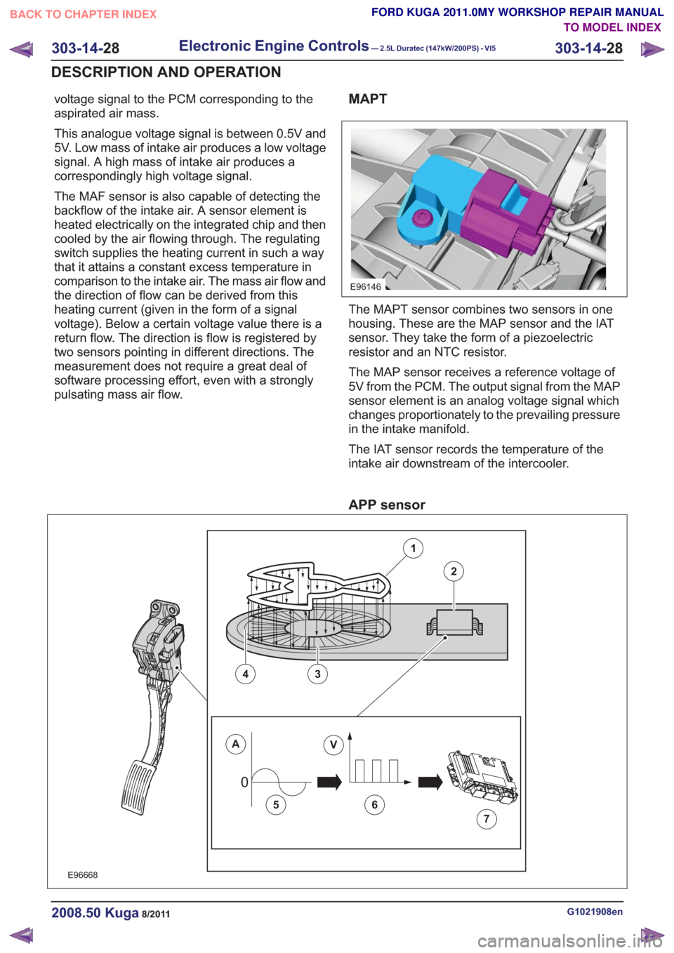
The MAPT sensor combines two sensors in one
housing. These are the MAP sensor and the IAT
sensor. They take the form of a piezoelectric
resistor and an NTC resistor.
The MAP sensor receives a reference voltage of
5V from the PCM. The output signal from the MAP
sensor element is an analog voltage signal which
changes proportionately to the prevailing pressure
in the intake manifold.
The IAT sensor records the temperature of the
intake air downstream of the intercooler.
APP sensor
00
E96668
1
2
43
AV
56
7
G1021908en2008.50 Kuga8/2011
303-14-28
Electronic Engine Controls— 2.5L Duratec (147kW/200PS) - VI5303-14-
28
DESCRIPTION AND OPERATION
TO MODEL INDEX
BACK TO CHAPTER INDEX
FORD KUGA 2011.0MY WORKSHOP REPAIR MANUAL
Page 1803 of 2057
Description
Item
Amperes
A
Volts
V
Valve rotor
1
Electronics
2
Primary coil
3
Secondary coil
4Description
Item
Analog alternating current
5
Generated PWM signal.
6
PCM
Comments:PWM signal is converted in the GEM
and forwarded via the CAN data bus.
7
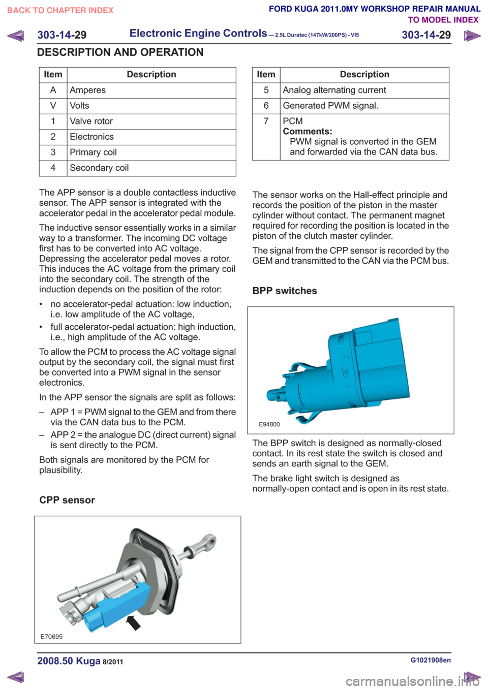
The APP sensor is a double contactless inductive
sensor. The APP sensor is integrated with the
accelerator pedal in the accelerator pedal module.
The inductive sensor essentially works in a similar
way to a transformer. The incoming DC voltage
first has to be converted into AC voltage.
Depressing the accelerator pedal moves a rotor.
This induces the AC voltage from the primary coil
into the secondary coil. The strength of the
induction depends on the position of the rotor:
• no accelerator-pedal actuation: low induction, i.e. low amplitude of the AC voltage,
• full accelerator-pedal actuation: high induction, i.e., high amplitude of the AC voltage.
To allow the PCM to process the AC voltage signal
output by the secondary coil, the signal must first
be converted into a PWM signal in the sensor
electronics.
In the APP sensor the signals are split as follows:
– APP 1 = PWM signal to the GEM and from there via the CAN data bus to the PCM.
– APP 2 = the analogue DC (direct current) signal is sent directly to the PCM.
Both signals are monitored by the PCM for
plausibility.
CPP sensor
E70695
The sensor works on the Hall-effect principle and
records the position of the piston in the master
cylinder without contact. The permanent magnet
required for recording the position is located in the
piston of the clutch master cylinder.
The signal from the CPP sensor is recorded by the
GEM and transmitted to the CAN via the PCM bus.
BPP switches
E94800
The BPP switch is designed as normally-closed
contact. In its rest state the switch is closed and
sends an earth signal to the GEM.
The brake light switch is designed as
normally-open contact and is open in its rest state.
G1021908en2008.50 Kuga8/2011
303-14- 29
Electronic Engine Controls— 2.5L Duratec (147kW/200PS) - VI5303-14-
29
DESCRIPTION AND OPERATION
TO MODEL INDEX
BACK TO CHAPTER INDEX
FORD KUGA 2011.0MY WORKSHOP REPAIR MANUAL
Page 1807 of 2057
Description
Item
Coil-on-plug ignition coil
1
Spark plug connector
2
Low-voltage connection
3
Laminated soft-iron core
4Description
Item
Primary winding
5
Secondary winding
6
Spark plug
7
High-voltage connection via spring contact
8
In an ignition system with coil-on-plug ignition coils,
each cylinder is actuated individually and only once
per cycle (working stroke). The coil-on-plug ignition
coils are mounted directly on the spark plugs,
therefore no ignition cables are required between
the ignition coils and the spark plugs.
Each individual ignition coil is actuated on the
low-voltage side by the PCM. The power
end-stages are incorporated into the coil-on-plug
ignition coils. Only the actuating current for these
power end-stages is controlled by the PCM.
Fuel pressure/fuel temperature sensor
E73531
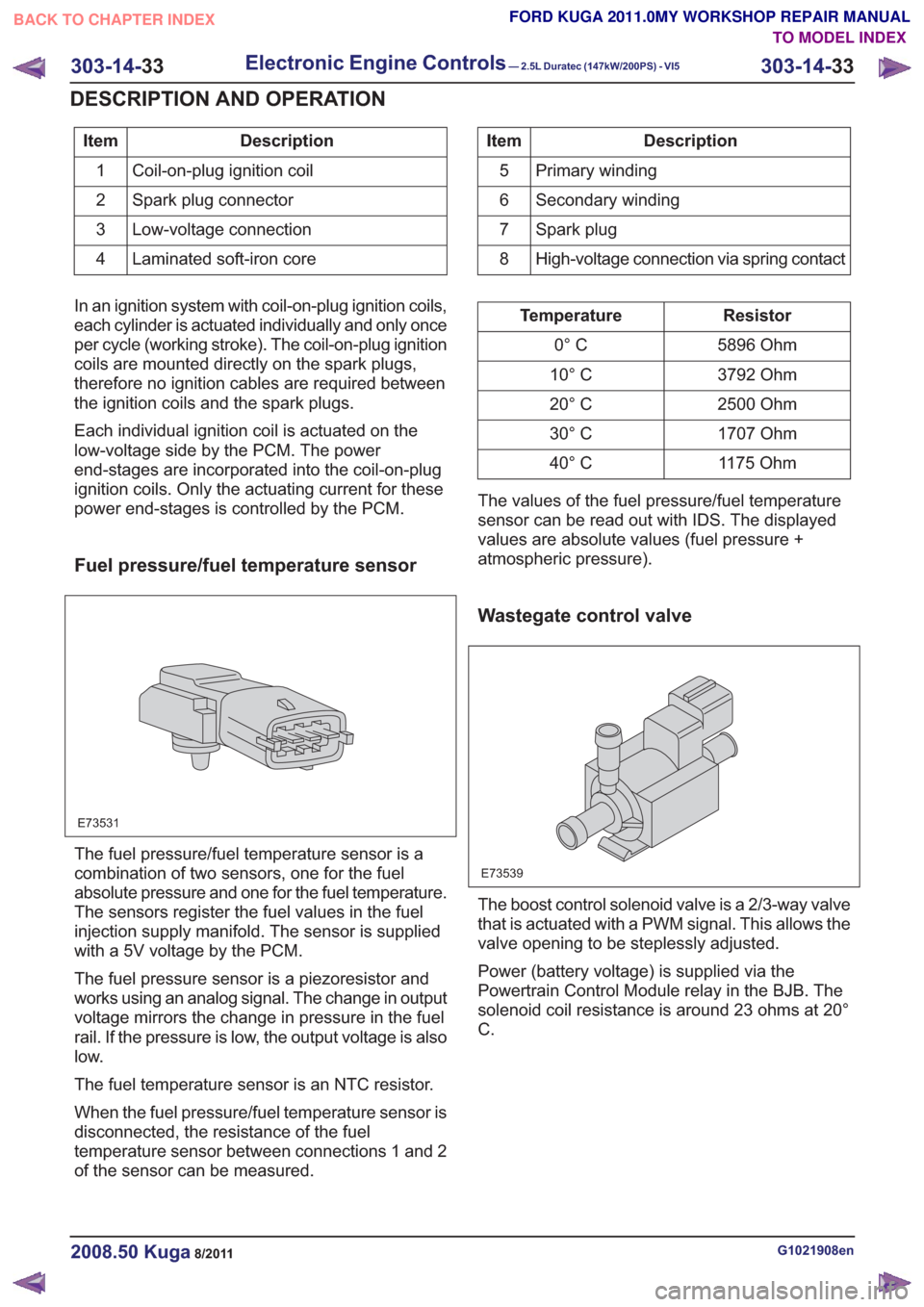
The fuel pressure/fuel temperature sensor is a
combination of two sensors, one for the fuel
absolute pressure and one for the fuel temperature.
The sensors register the fuel values in the fuel
injection supply manifold. The sensor is supplied
with a 5V voltage by the PCM.
The fuel pressure sensor is a piezoresistor and
works using an analog signal. The change in output
voltage mirrors the change in pressure in the fuel
rail. If the pressure is low, the output voltage is also
low.
The fuel temperature sensor is an NTC resistor.
When the fuel pressure/fuel temperature sensor is
disconnected, the resistance of the fuel
temperature sensor between connections 1 and 2
of the sensor can be measured.
Resistor
Temperature
5896 Ohm
0° C
3792 Ohm
10° C
2500 Ohm
20° C
1707 Ohm
30° C
1175 Ohm
40° C
The values of the fuel pressure/fuel temperature
sensor can be read out with IDS. The displayed
values are absolute values (fuel pressure +
atmospheric pressure).
Wastegate control valve
E73539
The boost control solenoid valve is a 2/3-way valve
that is actuated with a PWM signal. This allows the
valve opening to be steplessly adjusted.
Power (battery voltage) is supplied via the
Powertrain Control Module relay in the BJB. The
solenoid coil resistance is around 23 ohms at 20°
C.
G1021908en2008.50 Kuga8/2011
303-14- 33
Electronic Engine Controls— 2.5L Duratec (147kW/200PS) - VI5303-14-
33
DESCRIPTION AND OPERATION
TO MODEL INDEX
BACK TO CHAPTER INDEX
FORD KUGA 2011.0MY WORKSHOP REPAIR MANUAL
Page 1828 of 2057
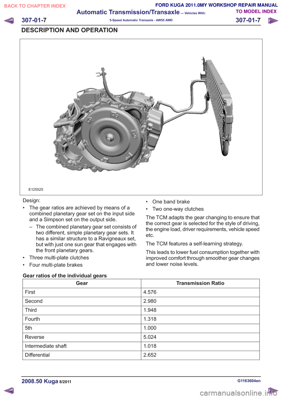
E125525
Design:
• The gear ratios are achieved by means of acombined planetary gear set on the input side
and a Simpson set on the output side.
– The combined planetary gear set consists oftwo different, simple planetary gear sets. It
has a similar structure to a Ravigneaux set,
but with just one sun gear that engages with
the front planetary gears.
• Three multi-plate clutches
• Four multi-plate brakes • One band brake
• Two one-way clutches
The TCM adapts the gear changing to ensure that
the correct gear is selected for the style of driving,
the engine load, driver requirements, vehicle speed
etc.
The TCM features a self-learning strategy.
This leads to lower fuel consumption together with
improved comfort through smoother gear changes
and lower noise levels.
Gear ratios of the individual gears
Transmission Ratio
Gear
4.576
First
2.980
Second
1.948
Third
1.318
Fourth
1.000
5th
5.024
Reverse
1.018
Intermediate shaft
2.652
Differential
G1163604en2008.50 Kuga8/2011
307-01- 7
Automatic Transmission/Transaxle
— Vehicles With:
5-Speed Automatic Transaxle - AW55 AWD
307-01- 7
DESCRIPTION AND OPERATION
TO MODEL INDEX
BACK TO CHAPTER INDEX
FORD KUGA 2011.0MY WORKSHOP REPAIR MANUAL
Page 1838 of 2057
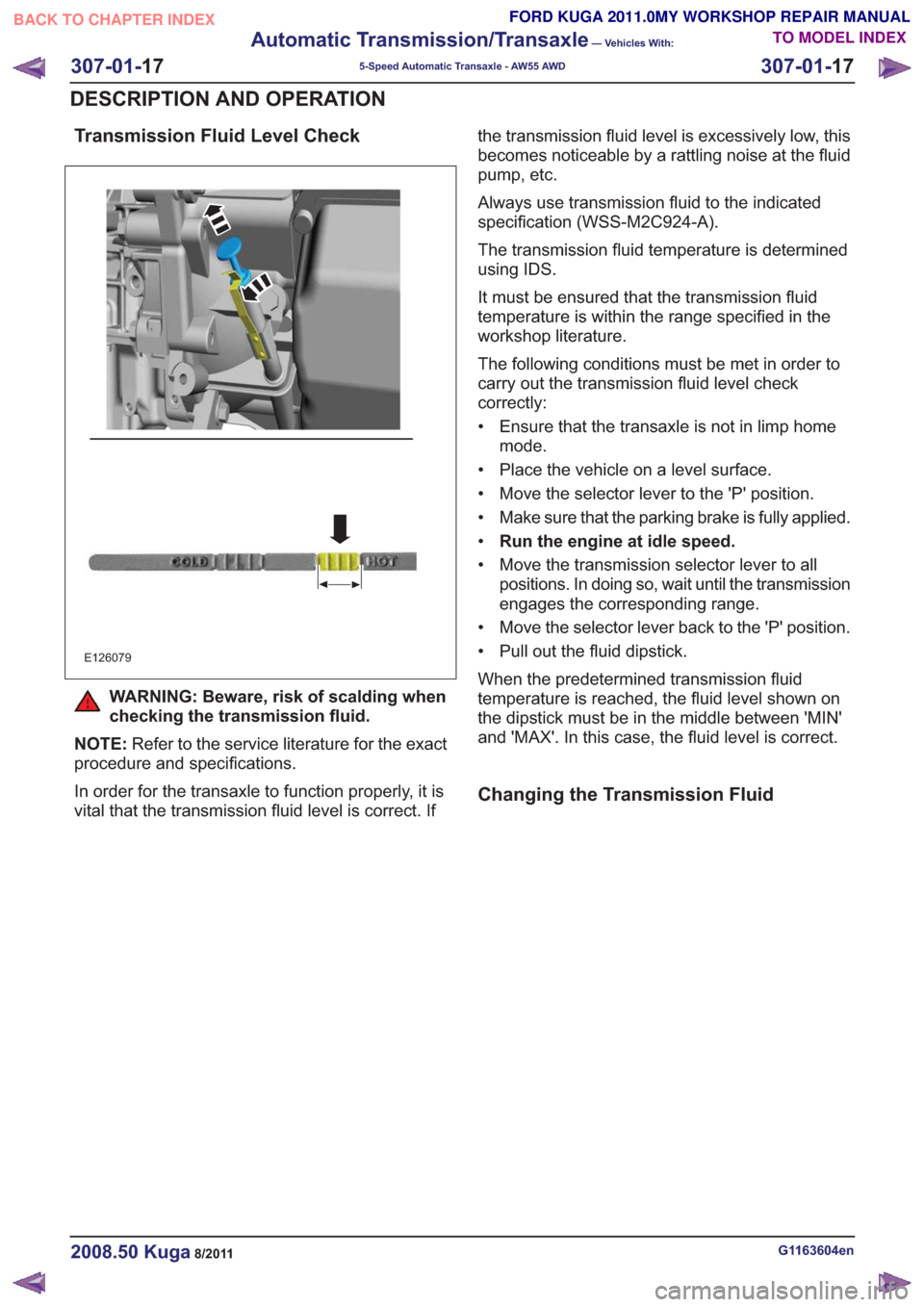
Transmission Fluid Level Check
E126079
WARNING: Beware, risk of scalding when
checking the transmission fluid.
NOTE: Refer to the service literature for the exact
procedure and specifications.
In order for the transaxle to function properly, it is
vital that the transmission fluid level is correct. If the transmission fluid level is excessively low, this
becomes noticeable by a rattling noise at the fluid
pump, etc.
Always use transmission fluid to the indicated
specification (WSS-M2C924-A).
The transmission fluid temperature is determined
using IDS.
It must be ensured that the transmission fluid
temperature is within the range specified in the
workshop literature.
The following conditions must be met in order to
carry out the transmission fluid level check
correctly:
• Ensure that the transaxle is not in limp home
mode.
• Place the vehicle on a level surface.
• Move the selector lever to the 'P' position.
• Make sure that the parking brake is fully applied.
• Run the engine at idle speed.
• Move the transmission selector lever to all positions. In doing so, wait until the transmission
engages the corresponding range.
• Move the selector lever back to the 'P' position.
• Pull out the fluid dipstick.
When the predetermined transmission fluid
temperature is reached, the fluid level shown on
the dipstick must be in the middle between 'MIN'
and 'MAX'. In this case, the fluid level is correct.
Changing the Transmission Fluid
G1163604en2008.50 Kuga8/2011
307-01- 17
Automatic Transmission/Transaxle
— Vehicles With:
5-Speed Automatic Transaxle - AW55 AWD
307-01- 17
DESCRIPTION AND OPERATION
TO MODEL INDEX
BACK TO CHAPTER INDEX
FORD KUGA 2011.0MY WORKSHOP REPAIR MANUAL
Page 1839 of 2057
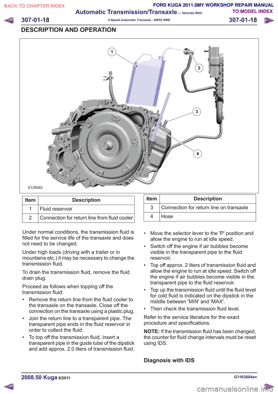
E126062
2
1
3
4
Description
Item
Fluid reservoir
1
Connection for return line from fluid cooler
2Description
Item
Connection for return line on transaxle
3
Hose
4
Under normal conditions, the transmission fluid is
filled for the service life of the transaxle and does
not need to be changed.
Under high loads (driving with a trailer or in
mountains etc.) it may be necessary to change the
transmission fluid.
To drain the transmission fluid, remove the fluid
drain plug.
Proceed as follows when topping off the
transmission fluid:
• Remove the return line from the fluid cooler to the transaxle on the transaxle. Close off the
connection on the transaxle using a plastic plug.
• Join the return line to a transparent pipe. The transparent pipe ends in the fluid reservoir in
order to collect the fluid.
• To top off the transmission fluid, insert a transparent pipe in the guide tube of the dipstick
and add approx. 2.0 liters of transmission fluid. • Move the selector lever to the 'P' position and
allow the engine to run at idle speed.
• Switch off the engine if air bubbles become visible in the transparent pipe to the fluid
reservoir.
• Top off approx. 2 liters of transmission fluid and allow the engine to run at idle speed. Switch off
the engine if air bubbles become visible in the
transparent pipe to the fluid reservoir.
• Top up the transmission fluid until the fluid level for cold fluid is indicated on the dipstick in the
middle between 'MIN' and 'MAX'.
• Then check the transmission fluid level.
Refer to the service literature for the exact
procedure and specifications.
NOTE: If the transmission fluid has been changed,
the counter for fluid change intervals must be reset
using IDS.
Diagnosis with IDS
G1163604en2008.50 Kuga8/2011
307-01- 18
Automatic Transmission/Transaxle
— Vehicles With:
5-Speed Automatic Transaxle - AW55 AWD
307-01- 18
DESCRIPTION AND OPERATION
TO MODEL INDEX
BACK TO CHAPTER INDEX
FORD KUGA 2011.0MY WORKSHOP REPAIR MANUAL
Page 1850 of 2057
To exactly determine the activation points of the
gear shifts and torque converter lockup on the
basis of the type of driving mode chosen, the TCM
receives the following information:
• Selected transmission range (TR sensor)
• Selected driving mode (normal/sport/select-shift)
• Transmission input shaft speed (TSS sensor)
• Transmission output shaft speed (OSS sensor)
• Transmission fluid temperature (TFT sensor)
• The engine speed and the torque as well as thethrottle plate opening - from the PCM via the
CAN databus
• Actuation of accelerator – from the PCM via the CAN databus
• The coolant temperature – from the PCM via the CAN databus
• Road speed – from the ABS module via the CAN databus
• Actuation of brake pedal – from the PCM via the CAN databus
Gearshift control
Adaptation
The TCM monitors every shift operation in all
driving conditions to make even and smooth gear
shifts possible. This is done by the control module,
which either lowers or increases the hydraulic line
pressure during gearshifts.
The changed pressure values are stored in the
control module memory after the engine is switched
off and retrieved during engine starting. This
improves the shift comfort and extends the service
life.
Full adaptability occurs when the following criteria
are met:
• Throttle plate opening is constant.
• Transmission fluid temperature between 65 °Cand 110 °C.
Shifting from 'P' to another transmission
range
To be able to move the selector lever from 'P' into
another transmission range, the ignition must be
switched on and the brake pedal pressed (stoplamp
switch on). The TCM detects the position of the
brake pedal via the CAN data bus and the engaged
transmission range from the TR sensor. Based on this information, the TCM transmits a
signal to the select-shift switch module. This
activates the brake shift interlock actuator in the
selector lever assembly.
When the brake shift interlock actuator is activated,
the locking pin is retracted so that another
transmission range can be selected.
The brake shift interlock actuator is deactivated
when the ignition is switched off. It is mechanically
locked when the gear selector lever is in 'P'.
Automatic transmission, selector lever in
position "D".
The TCM adapts the shift points to match the
driving conditions. Normally the TCM is in adaptive
mode and gear changes take place adapted to the
driving conditions. If special driving conditions are
detected, the TCM switches to predefined
characteristics.
When driving with normal acceleration, the TCM
uses a preset shift program which is optimized for
economical driving.
This shift program is suitable for "normal" driving
and delivers early upward changes and torque
converter lockup. Furthermore, the transmission
fluid pressure is adapted to make smooth
engagement of the gears possible.
Sport mode, selector lever in position "S"
The transmission switches from automatic
operation into sport mode. In this mode the TCM
switches to another set of characteristic curves.
These characteristic curves for control of the gear
changes are adapted to sporting calculations (e.g.
gear change at higher engine speed).
In the sport mode shift program the shift points are
set so that good performance is offered. Changing
down occurs at lower engine speeds.
Manual gear changes (select-shift mode) can be
made in sport mode by moving the selector lever
in the (+) or (-) direction.
Changing gear in select-shift mode
If you move the selector lever to 'S', the automatic
transaxle remains hydraulically in 'D' position. If
you move the gear selector lever forwards (-), the
G1163605en2008.50 Kuga8/2011
307-01-
29
Automatic Transmission/Transaxle
— Vehicles With:
5-Speed Automatic Transaxle - AW55 AWD
307-01- 29
DESCRIPTION AND OPERATION
TO MODEL INDEX
BACK TO CHAPTER INDEX
FORD KUGA 2011.0MY WORKSHOP REPAIR MANUAL