Page 1624 of 2057
E122294
x5
30.
E122227
31. CAUTION: Note the position of thecomponents before removal.
G543498en2008.50 Kuga8/2011
303-01- 91
Engine— 2.5L Duratec (147kW/200PS) - VI5303-01-
91
DISASSEMBLY
TO MODEL INDEX
BACK TO CHAPTER INDEX
FORD KUGA 2011.0MY WORKSHOP REPAIR MANUAL
Page 1628 of 2057
6
1
2
3
4
5
6
E122606
1
2
3
4
5
6
123456
2. CAUTION: Make sure that thecomponents are installed to the position
noted before removal.Apply a thin coating.
Material: Engine Oil - 5W-30 (WSS-M2C913-C)engine oil
G543500en2008.50 Kuga8/2011
303-01- 95
Engine— 2.5L Duratec (147kW/200PS) - VI5303-01-
95
ASSEMBLY
TO MODEL INDEX
BACK TO CHAPTER INDEX
FORD KUGA 2011.0MY WORKSHOP REPAIR MANUAL
Page 1629 of 2057
E122293
x5
3. CAUTION: Make sure that thecomponents are installed to the position
noted before removal.Apply a thin coating.
Material: Engine Oil - 5W-30 (WSS-M2C913-C)engine oil
G543500en2008.50 Kuga8/2011
303-01- 96
Engine— 2.5L Duratec (147kW/200PS) - VI5303-01-
96
ASSEMBLY
TO MODEL INDEX
BACK TO CHAPTER INDEX
FORD KUGA 2011.0MY WORKSHOP REPAIR MANUAL
Page 1633 of 2057
E122634
1
2
3
4
5
12345
11. CAUTION: Make sure that thecomponents are installed to the position
noted before removal.
General Equipment: Piston Ring Compressor
E122334
x5
12. CAUTION: Make sure that thecomponents are installed to the position
noted before removal.
Apply a thin coating.
Material: Engine Oil - 5W-30 (WSS-M2C913-C)engine oil
E77266
13. CAUTIONS:
Make sure that the components are
installed to the position noted before
removal.
Make sure that new bolts are installed.
G543500en2008.50 Kuga8/2011
303-01- 100
Engine— 2.5L Duratec (147kW/200PS) - VI5303-01-
100
ASSEMBLY
TO MODEL INDEX
BACK TO CHAPTER INDEX
FORD KUGA 2011.0MY WORKSHOP REPAIR MANUAL
Page 1695 of 2057

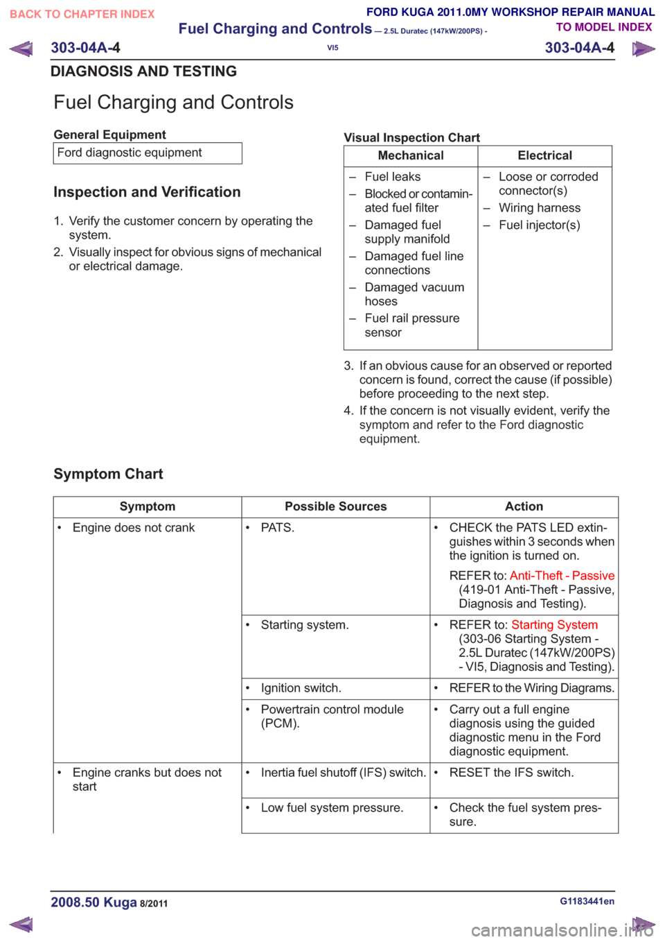
Fuel Charging and Controls
General EquipmentFord diagnostic equipment
Inspection and Verification
1. Verify the customer concern by operating the system.
2. Visually inspect for obvious signs of mechanical or electrical damage. Visual Inspection Chart
Electrical
Mechanical
– Loose or corrodedconnector(s)
– Wiring harness
– Fuel injector(s)
– Fuel leaks
– Blocked or contamin-
ated fuel filter
– Damaged fuel supply manifold
– Damaged fuel line connections
– Damaged vacuum hoses
– Fuel rail pressure sensor
3. If an obvious cause for an observed or reported concern is found, correct the cause (if possible)
before proceeding to the next step.
4. If the concern is not visually evident, verify the symptom and refer to the Ford diagnostic
equipment .
Symptom Chart
Action
Possible Sources
Symptom
• CHECK the PATS LED extin-guishes within 3 seconds when
the ignition is turned on.
REFER to: Anti-Theft - Passive
(419-01 Anti-Theft - Passive,
Diagnosis and Testing).
• PAT S .
• Engine does not crank
• REFER to:Starting System
(303-06 Starting System -
2.5L Duratec (147kW/200PS)
- VI5, Diagnosis and Testing).
• Starting system.
• REFER to the Wiring Diagrams.
• Ignition switch.
• Carry out a full enginediagnosis using the guided
diagnostic menu in the Ford
diagnostic equipment.
• Powertrain control module
(PCM).
• RESET the IFS switch.
• Inertia fuel shutoff (IFS) switch.
• Engine cranks but does not
start
• Check the fuel system pres-sure.
• Low fuel system pressure.
G1183441en2008.50 Kuga8/2011
303-04A-
4
Fuel Charging and Controls
— 2.5L Duratec (147kW/200PS) -
VI5
303-04A- 4
DIAGNOSIS AND TESTING
TO MODEL INDEX
BACK TO CHAPTER INDEX
FORD KUGA 2011.0MY WORKSHOP REPAIR MANUAL
Page 1722 of 2057

Description
Item
PWM (pulse width modulation) signal
Comments:from PCM (powertrain control module)
5
Atmospheric pressure
6
Turbocharger boost pressure.
7
from air filter
8
Intake air
9Description
Item
Recirculated air valveRefertoComponentDescription:(page
7)
10
Vacuum line, recirculated air valve
11
to intake manifold
12
Throttle plate
13
Compressor
14
Turbine
15
System Operation
Turbocharger(s)
The TC consists of a turbine and a compressor.
The turbine is driven by the exhaust gas flow. A
common shaft drives the compressor and this then
compresses the intake air.
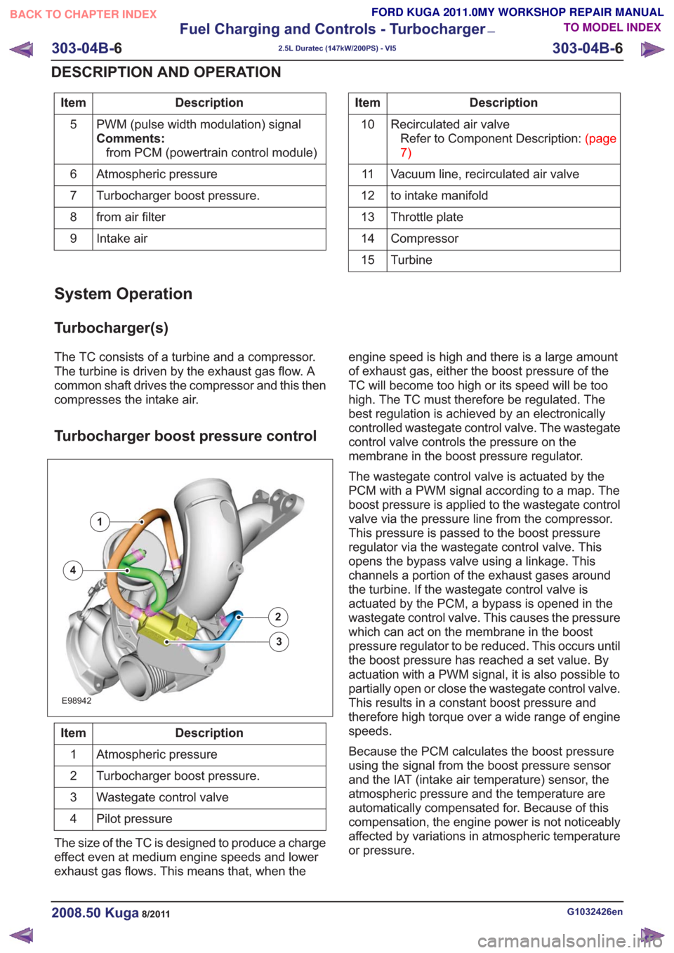
Turbocharger boost pressure control
E98942
1
2
3
4
Description
Item
Atmospheric pressure
1
Turbocharger boost pressure.
2
Wastegate control valve
3
Pilot pressure
4
The size of the TC is designed to produce a charge
effect even at medium engine speeds and lower
exhaust gas flows. This means that, when the engine speed is high and there is a large amount
of exhaust gas, either the boost pressure of the
TC will become too high or its speed will be too
high. The TC must therefore be regulated. The
best regulation is achieved by an electronically
controlled wastegate control valve. The wastegate
control valve controls the pressure on the
membrane in the boost pressure regulator.
The wastegate control valve is actuated by the
PCM with a PWM signal according to a map. The
boost pressure is applied to the wastegate control
valve via the pressure line from the compressor.
This pressure is passed to the boost pressure
regulator via the wastegate control valve. This
opens the bypass valve using a linkage. This
channels a portion of the exhaust gases around
the turbine. If the wastegate control valve is
actuated by the PCM, a bypass is opened in the
wastegate control valve. This causes the pressure
which can act on the membrane in the boost
pressure regulator to be reduced. This occurs until
the boost pressure has reached a set value. By
actuation with a PWM signal, it is also possible to
partially open or close the wastegate control valve.
This results in a constant boost pressure and
therefore high torque over a wide range of engine
speeds.
Because the PCM calculates the boost pressure
using the signal from the boost pressure sensor
and the IAT (intake air temperature) sensor, the
atmospheric pressure and the temperature are
automatically compensated for. Because of this
compensation, the engine power is not noticeably
affected by variations in atmospheric temperature
or pressure.
G1032426en2008.50 Kuga8/2011
303-04B-
6
Fuel Charging and Controls - Turbocharger
—
2.5L Duratec (147kW/200PS) - VI5
303-04B- 6
DESCRIPTION AND OPERATION
TO MODEL INDEX
BACK TO CHAPTER INDEX
FORD KUGA 2011.0MY WORKSHOP REPAIR MANUAL
Page 1725 of 2057

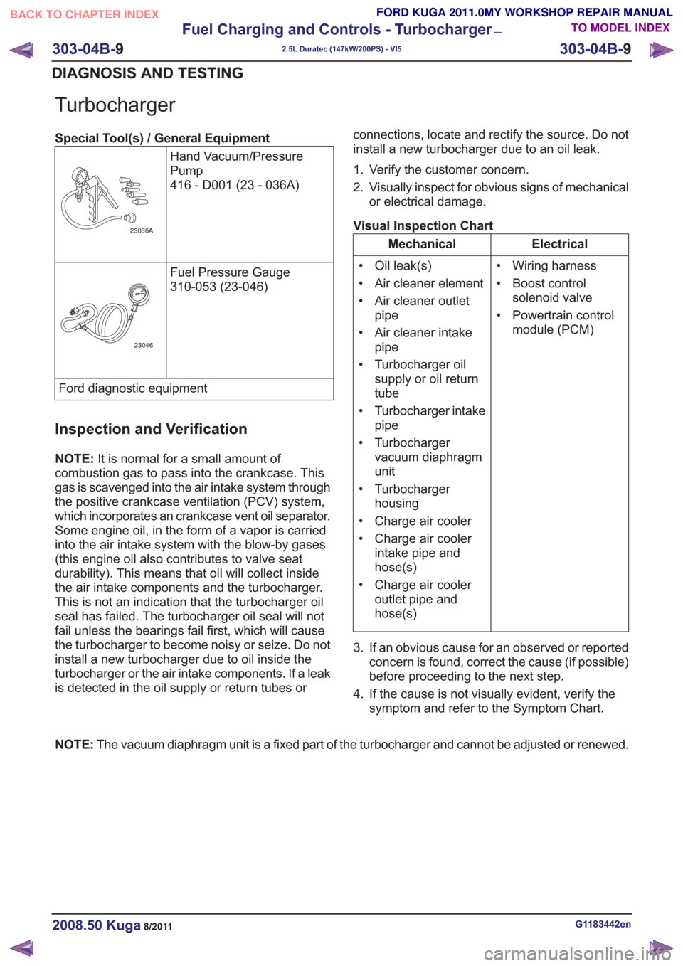
Turbocharger
Special Tool(s) / General EquipmentHand Vacuum/Pressure
Pump
416 - D001 (23 - 036A)
23036A
Fuel Pressure Gauge
310-053 (23-046)
23046
Ford diagnostic equipment
Inspection and Verification
NOTE:It is normal for a small amount of
combustion gas to pass into the crankcase. This
gas is scavenged into the air intake system through
the positive crankcase ventilation (PCV) system,
which incorporates an crankcase vent oil separator.
Some engine oil, in the form of a vapor is carried
into the air intake system with the blow-by gases
(this engine oil also contributes to valve seat
durability). This means that oil will collect inside
the air intake components and the turbocharger.
This is not an indication that the turbocharger oil
seal has failed. The turbocharger oil seal will not
fail unless the bearings fail first, which will cause
the turbocharger to become noisy or seize. Do not
install a new turbocharger due to oil inside the
turbocharger or the air intake components. If a leak
is detected in the oil supply or return tubes or connections, locate and rectify the source. Do not
install a new turbocharger due to an oil leak.
1. Verify the customer concern.
2. Visually inspect for obvious signs of mechanical
or electrical damage.
Visual Inspection Chart
Electrical
Mechanical
• Wiring harness
• Boost controlsolenoid valve
• Powertrain control module (PCM)
• Oil leak(s)
• Air cleaner element
• Air cleaner outlet
pipe
• Air cleaner intake pipe
• Turbocharger oil supply or oil return
tube
• Turbocharger intake pipe
• Turbocharger vacuum diaphragm
unit
• Turbocharger housing
• Charge air cooler
• Charge air cooler intake pipe and
hose(s)
• Charge air cooler outlet pipe and
hose(s)
3. If an obvious cause for an observed or reported concern is found, correct the cause (if possible)
before proceeding to the next step.
4. If the cause is not visually evident, verify the symptom and refer to the Symptom Chart.
NOTE: The vacuum diaphragm unit is a fixed part of the turbocharger and cannot be adjusted or renewed.
G1183442en2008.50 Kuga8/2011
303-04B- 9
Fuel Charging and Controls - Turbocharger
—
2.5L Duratec (147kW/200PS) - VI5
303-04B- 9
DIAGNOSIS AND TESTING
TO MODEL INDEX
BACK TO CHAPTER INDEX
FORD KUGA 2011.0MY WORKSHOP REPAIR MANUAL
Page 1734 of 2057

Accessory Drive
Inspection and Verification
1. Verify the customer concern.
2. Visually inspect for obvious signs of mechanicaldamage.
Visual Inspection Chart
Mechanical
– Damaged or contaminated accessory drive belt or air conditioning (A/C) compressor belt
– Damaged or contaminated pulley(s)
– Incorrect accessory drive belt or A/C compressor belt
– Incorrect fitment of the accessory drive belt or A/C compressor belt
– Accessory drive belt tensioner
– Accessory drive belt idler pulley
– Generator
– A/C compressor
– A/C compressor belt tensioner
– Pulley(s)
– Loose hardware
3. If an obvious cause for an observed or reported concern is found, correct the cause (if possible)
before proceeding to the next step.
Accessory Drive Belt Concerns
CAUTION: Do not lubricate the accessory
drive belt, accessory drive belt tensioner(s)
or idler pulley(s) as potential damage to
the accessory drive belt material
construction, accessory drive belt
tensioner damping mechanism, accessory
drive belt tensioner pulley bearing and idler
pulley(s) bearing may occur.
NOTE: All the diagnosis and testing information
contained within this procedure can be used for
the accessory drive belt and the A/C compressor
belt.
Cracking
Accessory drive belts are made from rubber which
hardens with time and can develop cracks. As the
accessory drive belt runs on the back of some of
the pulleys, the cracks are opened up. Small cracks
are not considered to be a failure of the accessory drive belt. Only if the crack is deep enough to reach
the bottom of the groove to expose the cord or any
chunks are found to be missing from the accessory
drive belt, is the accessory drive belt condition
considered to be unacceptable.
1. Check the accessory drive belt for cracks. If the
damage exceeds the acceptable limit, install a
new accessory drive belt.
REFER to: Accessory Drive Belt (303-05
Accessory Drive - 2.5L Duratec
(147kW/200PS) - VI5, Removal and
Installation).
and/or
REFER to: Air Conditioning (A/C) Compressor
Belt (303-05 Accessory Drive - 2.5L Duratec
(147kW/200PS) - VI5, Removal and
Installation).
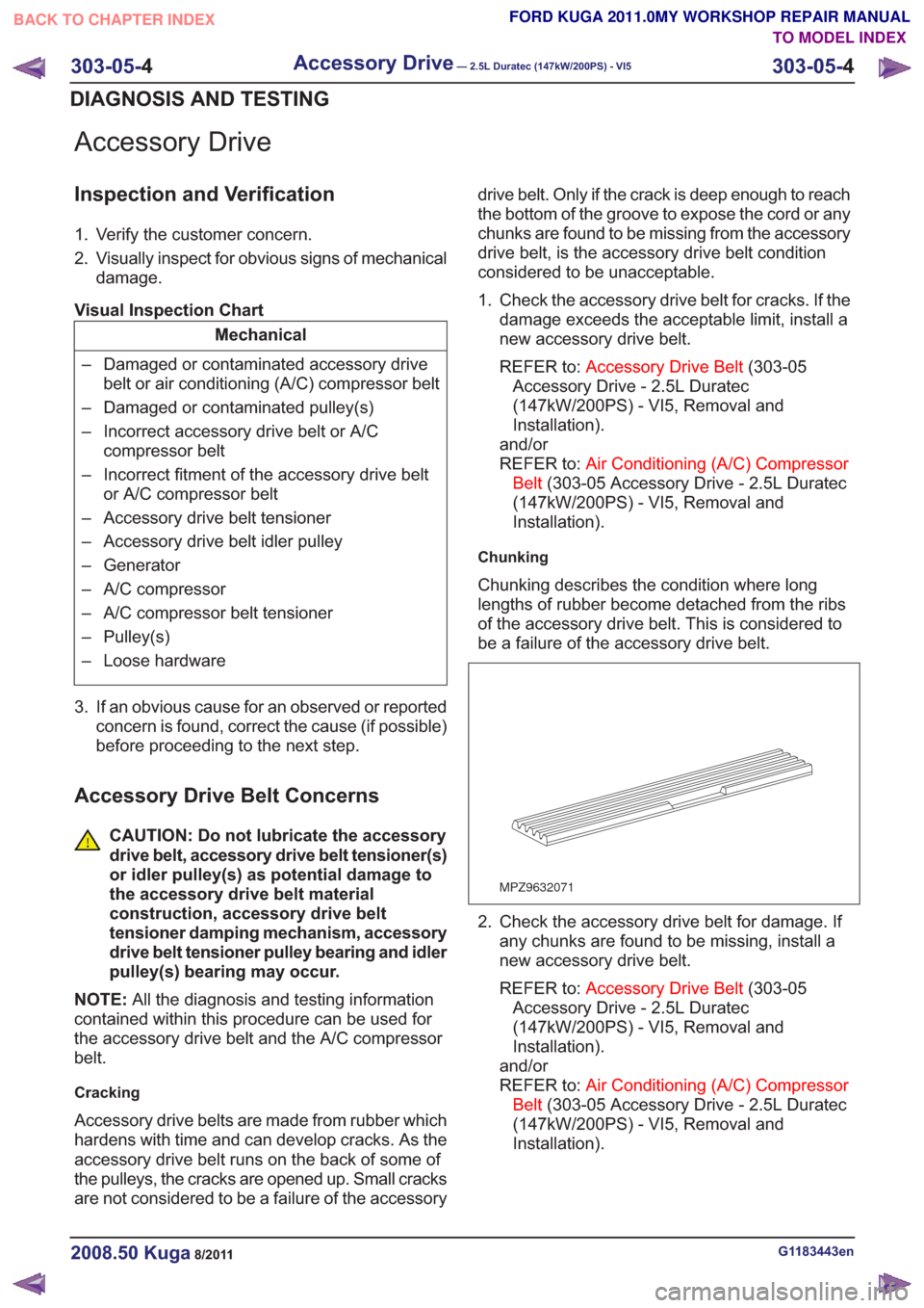
Chunking
Chunking describes the condition where long
lengths of rubber become detached from the ribs
of the accessory drive belt. This is considered to
be a failure of the accessory drive belt.
MPZ9632071
2. Check the accessory drive belt for damage. If any chunks are found to be missing, install a
new accessory drive belt.
REFER to: Accessory Drive Belt (303-05
Accessory Drive - 2.5L Duratec
(147kW/200PS) - VI5, Removal and
Installation).
and/or
REFER to: Air Conditioning (A/C) Compressor
Belt (303-05 Accessory Drive - 2.5L Duratec
(147kW/200PS) - VI5, Removal and
Installation).
G1183443en2008.50 Kuga8/2011
303-05- 4
Accessory Drive— 2.5L Duratec (147kW/200PS) - VI5303-05-
4
DIAGNOSIS AND TESTING
TO MODEL INDEX
BACK TO CHAPTER INDEX
FORD KUGA 2011.0MY WORKSHOP REPAIR MANUAL