2011 FORD KUGA transaxle
[x] Cancel search: transaxlePage 81 of 2057
Noise, Vibration and Harshness (NVH)
Inspection and Verification
1. Verify the customer concern.
2. Visually inspect for obvious signs of mechanicalor electrical damage.
3. If an obvious cause for an observed or reported concern is found, correct the cause (if possible)
before proceeding to the next step.
4. If the concern is not visually evident, verify the symptom and REFER to the Symptom Chart.
How to Use this Diagnostic Procedure
Section
• Noise, vibration and harshness (NVH) concernshave become more important as vehicles have
become more sensitive to these vibrations. This
section is designed to aid in identifying these
concerns.
• The section provides diagnostic procedures based on symptom. If the condition occurs at
high speed, for instance, the most likely place
to start is under Shake and Vibration While
Driving.
• The road test procedure will tell how to sort the conditions into categories and how to tell a
vibration from a shake.
• A series of Road Test Quick Checks are provided to make sure that a cause is either
pinpointed or eliminated.
• Name the condition, proceed to the appropriate section and locate the correct diagnosis. When
the condition is identified, the job is partly done.
• Follow the diagnostic procedure as outlined.
• Quick Checks are described within the step, while more involved tests and adjustments are
outlined in General Procedures.
• Always follow each step exactly and make notes to recall important findings later.
Customer Interview
The road test and customer interview (if available)
provide information that will help identify the
concern and will provide direction to the correct
starting point for diagnosis.
Identify the Condition
NVH usually occur in four areas:
• tires
• engine accessories
• suspension
• driveline
It is important, therefore, that an NVH concern be
isolated into its specific area(s) as soon as
possible. The easiest and quickest way to do this
is to carry out the Road Test as outlined. To assist
in the diagnosis and testing procedure(s), use a
suitable approved NVH diagnosis tester.
Noise Diagnostic Procedure
Non-Axle Noise
The five most common sources of non-axle noise
are exhaust, tires, roof racks, trim panels and
transmission.
Therefore, make sure that none of the following
conditions are the cause of the noise before
proceeding with a driveline teardown and
diagnosis.
• In certain conditions, the pitch of the exhaustmay sound very much like gear noise. At other
times, it can be mistaken for a wheel bearing
rumble.
• Tires, especially snow tires, can have a high pitched tread whine or roar, similar to gear
noise. Radial tires may have this characteristic.
Also, any non-standard tire with an unusual
tread construction may emit a roar or whine
noise.
• Trim panels can also cause whistling or whining noise.
• Clunk may be a metallic noise heard when the automatic transaxle is engaged in "R"
(REVERSE) or "D" (DRIVE) or it may occur
when the throttle is applied or released. It is
caused by backlash somewhere in the driveline.
• Bearing rumble sounds like marbles being tumbled. This condition is usually caused by a
damaged wheel bearing.
G37349en2008.50 Kuga8/2011
100-04- 2
Noise, Vibration and Harshness
100-04- 2
DIAGNOSIS AND TESTING
TO MODEL INDEX
BACK TO CHAPTER INDEX
FORD KUGA 2011.0MY WORKSHOP REPAIR MANUAL
Page 1246 of 2057
SECTION 205-02 Rear Drive Axle/Differential
VEHICLE APPLICATION:2008.50 Kuga
PA G E
CONTENTS
DESCRIPTION AND OPERATION
205-02-2
Rear Drive Axle and Differential (Component Location) .....................................................
205-02-6
Rear Drive Axle and Differential (System Operation and Component Description) ...........
205-02-6
System Operation ........................................................................\
.......................................
205-02-6
General Information ........................................................................\
................................
205-02-6
Driving situations ........................................................................\
....................................
205-02-6
Haldex clutch ........................................................................\
..........................................
205-02-7
General overview ........................................................................\
....................................
205-02-7
Operation ........................................................................\
................................................
205-02-7
Design of the 3rd generation Haldex clutch ....................................................................
205-02-9
Design of the multi-plate clutch ........................................................................\
...............
205-02-10
All-wheel drive control unit ........................................................................\
......................
205-02-10
Electric feed pump ........................................................................\
..................................
205-02-10
Pressure control - 3rd generation Haldex clutch .............................................................
205-02-11
Base pressure ........................................................................\
.........................................
205-02-12
Increased base pressure (preload) ........................................................................\
.........
205-02-13
Pressure build-up ........................................................................\
....................................
205-02-14
Design of the 4th generation Haldex clutch ...................................................................
205-02-14
General overview ........................................................................\
....................................
205-02-15
Pressure control - 4th generation Haldex clutch .............................................................
GENERAL PROCEDURES 205-02-17
Differential Fluid Level Check ........................................................................\
.....................
205-02-19
Active On-Demand Coupling Fluid Level Check ................................................................
REMOVAL AND INSTALLATION 205-02-21
Differential Case ........................................................................\
.........................................
205-02-25
Active On-Demand Coupling Module ........................................................................\
.........
205-02-32
Differential Input Shaft Seal ........................................................................\
........................
205-02-38
Differential Support Insulator ........................................................................\
......................
205-02-39
Rear Halfshaft Seal ........................................................................\
.....................................
205-02-41
Drive Pinion Seal ........................................................................\
........................................
DISASSEMBLY AND ASSEMBLY
205-02-42
Active On-Demand Coupling — Vehicles With: 5-Speed Automatic Transaxle - AW55
AWD/6-Speed Automatic Transaxle - 6DCT450 ...............................................................
205-02-1
Rear Drive Axle/Differential
205-02- 1
.
TO MODEL INDEX
BACK TO CHAPTER INDEX
FORD KUGA 2011.0MY WORKSHOP REPAIR MANUAL
Page 1251 of 2057
Rear Drive Axle and Differential – System Operation andComponent Description
System Operation
General Information
The powertrain with all-wheel drive consists of the
following main components:
• engine
• transaxle with front axle differential
• transfer box
• halfshafts and driveshafts
• Haldex clutch
• rear axle differential
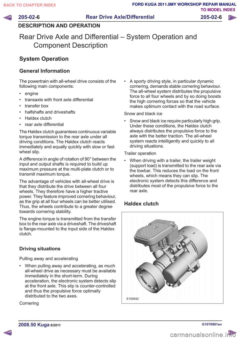
The Haldex clutch guarantees continuous variable
torque transmission to the rear axle under all
driving conditions. The Haldex clutch reacts
immediately and equally quickly with slow or fast
wheel slip.
A difference in angle of rotation of 90° between the
input and output shafts is required to build up
maximum pressure at the multi-plate clutch or to
transmit maximum torque.
The advantage of vehicles with all-wheel drive is
that they distribute the drive between all four
wheels. They therefore have a higher tractive
power. They feature improved cornering behaviour,
as the grip at all four wheels can be better utilised.
Thus, the wheels contribute to a greater degree
towards cornering stability.
The engine torque is transmitted from the transfer
box to the rear axle via a driveshaft. The driveshaft
is flange-mounted to the input side of the Haldex
clutch.
Driving situations
Pulling away and accelerating
• When pulling away and accelerating, as muchall-wheel drive as necessary must be available
immediately in the short-term. During
acceleration, the electronic system detects slip
at the front axle. This slip is counter-controlled
and thus the propulsive force optimally
distributed to the two axes.
Cornering • A sporty driving style, in particular dynamic
cornering, demands stable cornering behaviour.
The all-wheel system distributes the propulsive
force to all four wheels and by so doing boosts
the high cornering forces so that the vehicle
makes optimum contact with the road surface.
Snow and black ice
• Snow and black ice require particularly high grip. Under these conditions, the Haldex clutch
always distributes the propulsive force to the
axle with the better traction. The all-wheel
system reacts intelligently and quickly to all
driving situations.
Trailer operation
• When driving with a trailer, the trailer weight (support load) is transmitted to the rear axle via
the towbar. This reduces the load on the front
wheels, which means they can slip. The
electronic system detects this difference and
distributes most of the propulsive force to the
rear axle.
Haldex clutch
E100642
G1076981en2008.50 Kuga8/2011
205-02- 6
Rear Drive Axle/Differential
205-02- 6
DESCRIPTION AND OPERATION
TO MODEL INDEX
BACK TO CHAPTER INDEX
FORD KUGA 2011.0MY WORKSHOP REPAIR MANUAL
Page 1287 of 2057
Active On-Demand Coupling — Vehicles With: 5-Speed AutomaticTransaxle - AW55 AWD/6-Speed Automatic Transaxle -
6DCT450
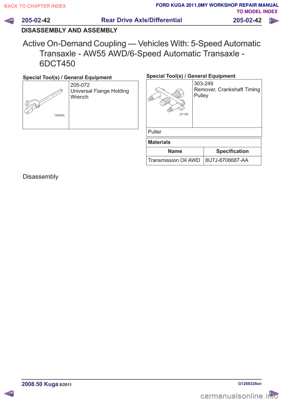
Special Tool(s) / General Equipment
205-072
Universal Flange Holding
Wrench
15030A
Special Tool(s) / General Equipment303-249
Remover, Crankshaft Timing
Pulley
21132
Puller
Materials
Specification
Name
8U7J-8708687-AA
Transmission Oil AWD
Disassembly
G1268328en2008.50 Kuga8/2011
205-02- 42
Rear Drive Axle/Differential
205-02- 42
DISASSEMBLY AND ASSEMBLY
TO MODEL INDEX
BACK TO CHAPTER INDEX
FORD KUGA 2011.0MY WORKSHOP REPAIR MANUAL
Page 1299 of 2057
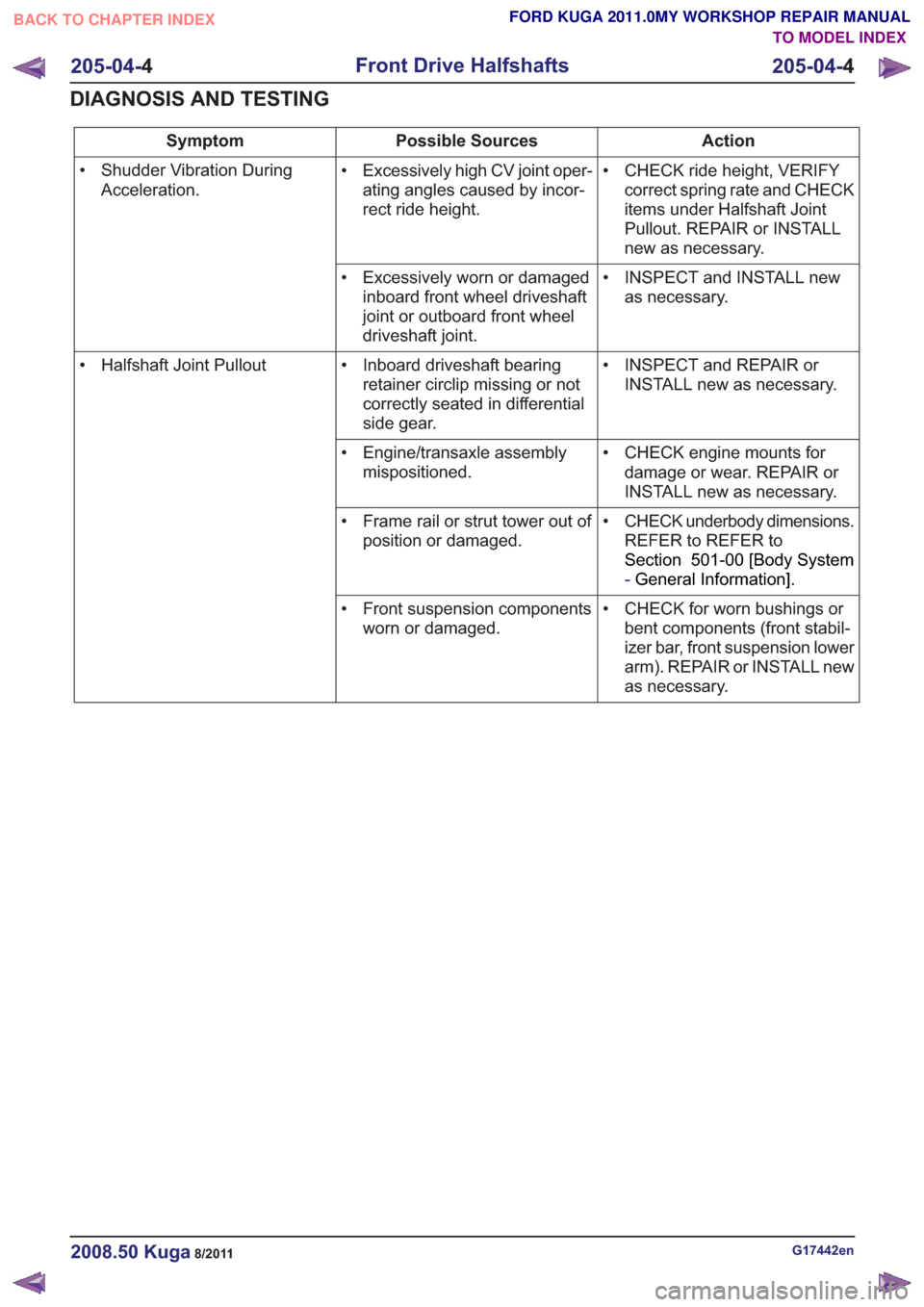
Action
Possible Sources
Symptom
• CHECK ride height, VERIFYcorrect spring rate and CHECK
items under Halfshaft Joint
Pullout. REPAIR or INSTALL
new as necessary.
• Excessively high CV joint oper-
ating angles caused by incor-
rect ride height.
• Shudder Vibration During
Acceleration.
• INSPECT and INSTALL newas necessary.
• Excessively worn or damaged
inboard front wheel driveshaft
joint or outboard front wheel
driveshaft joint.
• INSPECT and REPAIR orINSTALL new as necessary.
• Inboard driveshaft bearing
retainer circlip missing or not
correctly seated in differential
side gear.
• Halfshaft Joint Pullout
• CHECK engine mounts fordamage or wear. REPAIR or
INSTALL new as necessary.
• Engine/transaxle assembly
mispositioned.
• CHECK underbody dimensions.REFER to REFER to
Section 501-00 [Body System
-General Information] .
• Frame rail or strut tower out of
position or damaged.
• CHECK for worn bushings orbent components (front stabil-
izer bar, front suspension lower
arm). REPAIR or INSTALL new
as necessary.
• Front suspension components
worn or damaged.
G17442en2008.50 Kuga8/2011
205-04- 4
Front Drive Halfshafts
205-04- 4
DIAGNOSIS AND TESTING
TO MODEL INDEX
BACK TO CHAPTER INDEX
FORD KUGA 2011.0MY WORKSHOP REPAIR MANUAL
Page 1304 of 2057
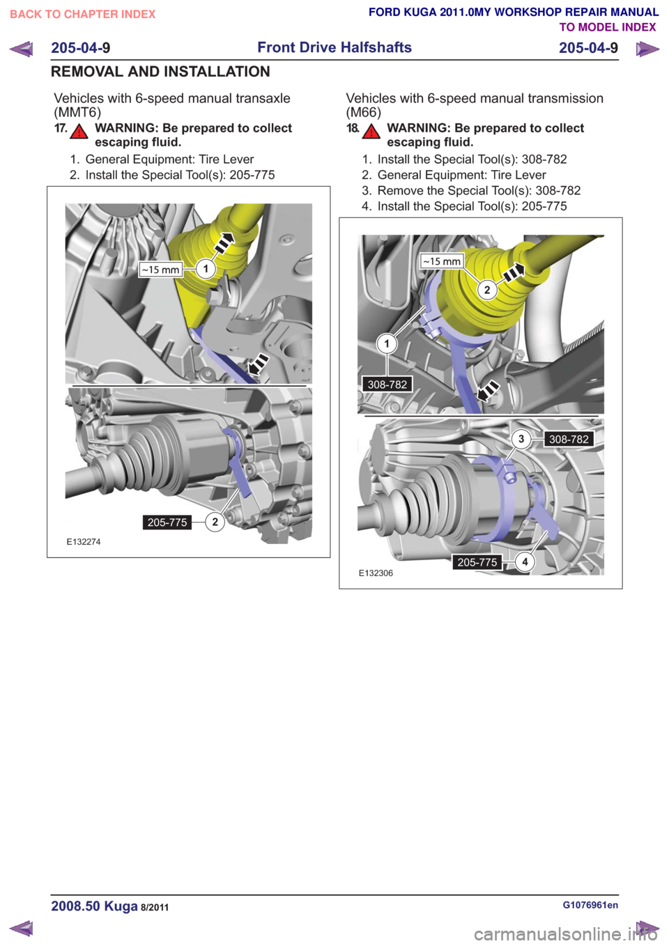
Vehicles with 6-speed manual transaxle
(MMT6)
17. WARNING: Be prepared to collectescaping fluid.
1. General Equipment: Tire Lever
2. Install the Special Tool(s): 205-775
1
205-7752
1
205-7752
E132274
Vehicles with 6-speed manual transmission
(M66)
18. WARNING: Be prepared to collectescaping fluid.
1. Install the Special Tool(s): 308-782
2. General Equipment: Tire Lever
3. Remove the Special Tool(s): 308-782
4. Install the Special Tool(s): 205-775
2
205-7754
308-7823
308-782
1
2
205-7754
308-7823
308-782
1
E132306
G1076961en2008.50 Kuga8/2011
205-04- 9
Front Drive Halfshafts
205-04- 9
REMOVAL AND INSTALLATION
TO MODEL INDEX
BACK TO CHAPTER INDEX
FORD KUGA 2011.0MY WORKSHOP REPAIR MANUAL
Page 1305 of 2057
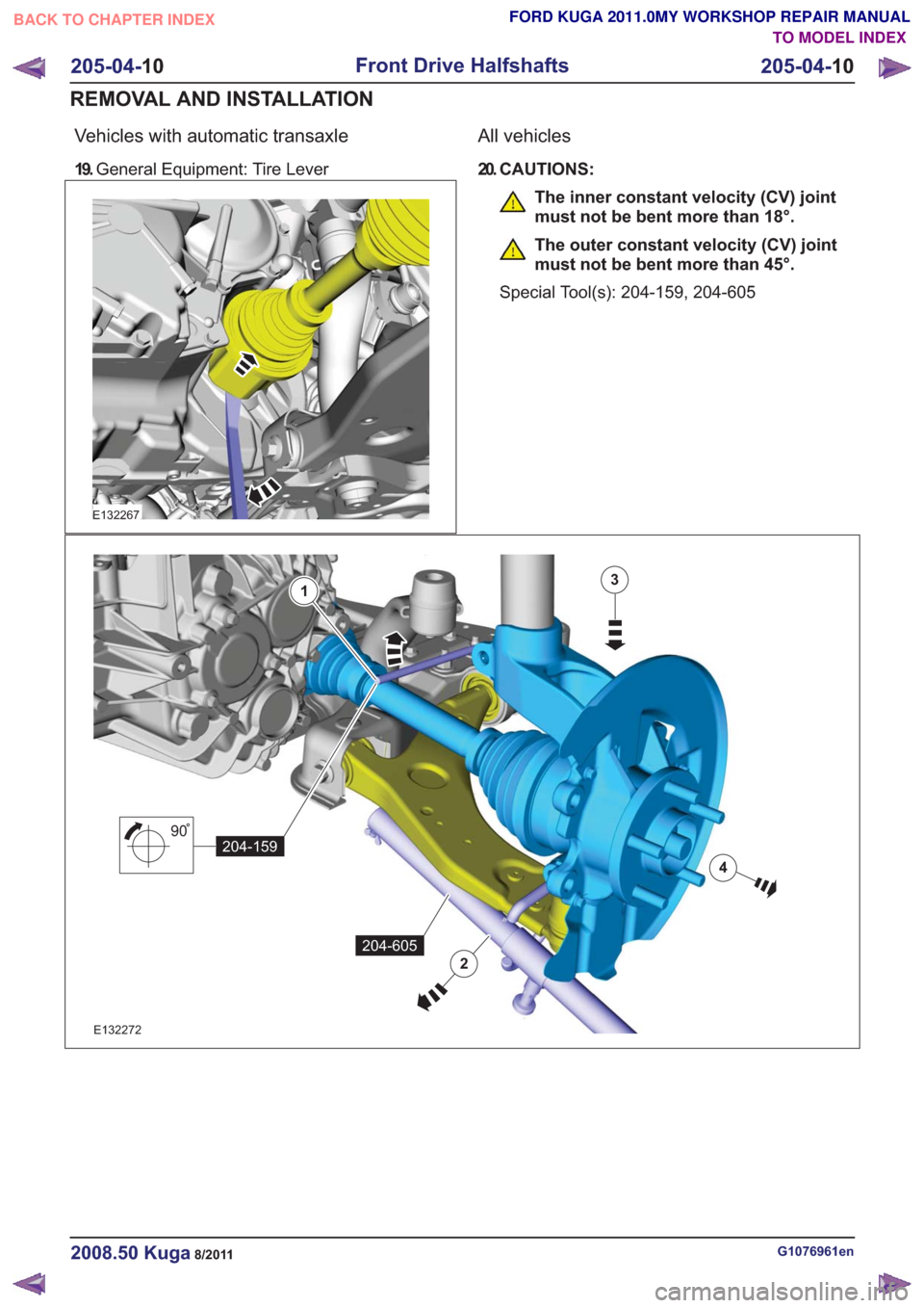
Vehicles with automatic transaxle
19.General Equipment: Tire Lever
E132267
All vehicles
20. CAUTIONS:
The inner constant velocity (CV) joint
must not be bent more than 18°.
The outer constant velocity (CV) joint
must not be bent more than 45°.
Special Tool(s): 204-159, 204-605
90
204-159
3
4
1
2
204-605
90
204-159
3
4
1
2
204-605
E132272
G1076961en2008.50 Kuga8/2011
205-04- 10
Front Drive Halfshafts
205-04- 10
REMOVAL AND INSTALLATION
TO MODEL INDEX
BACK TO CHAPTER INDEX
FORD KUGA 2011.0MY WORKSHOP REPAIR MANUAL
Page 1314 of 2057
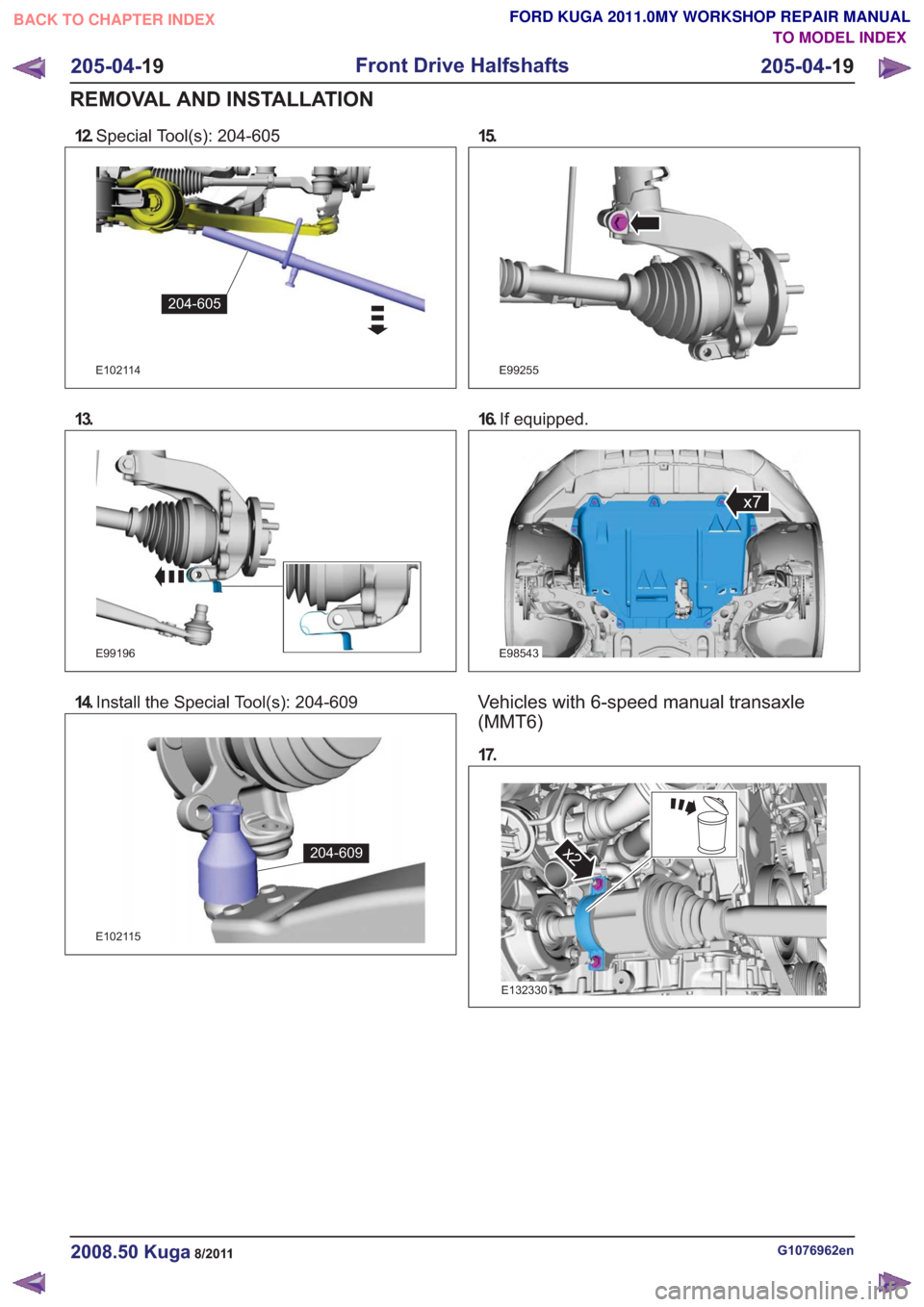
12.Special Tool(s): 204-605
E102114
204-605
13.
E99196
14.Install the Special Tool(s): 204-609
E102115
204-609
15.
E99255
16.If equipped.
E98543
x7
Vehicles with 6-speed manual transaxle
(MMT6)
17.
x2x2
E132330
G1076962en2008.50 Kuga8/2011
205-04- 19
Front Drive Halfshafts
205-04- 19
REMOVAL AND INSTALLATION
TO MODEL INDEX
BACK TO CHAPTER INDEX
FORD KUGA 2011.0MY WORKSHOP REPAIR MANUAL