2011 FORD KUGA tire pressure
[x] Cancel search: tire pressurePage 63 of 2057

Road/Roller Testing
Road or roller testing may be carried out for various
reasons and a procedure detailing pre-test checks,
engine starting and stopping, pre-driving checks,
on-test checks and final checks to be completed
on completion of the test is given below.
Unless complete vehicle performance is being
checked, the full road test procedure need not be
carried out. Instead, those items particularly
relevant to the system(s) being checked can be
extracted.
Pre-Test Checks
WARNING: If the brake system hydraulic
fluid level is low, pedal travel is excessive
or a hydraulic leak is found, do not attempt
to road test the vehicle until the reason for
the low fluid level, excessive pedal travel
or hydraulic leak is found and rectified.
It is suggested that pre-test checks and functional
tests of those systems and circuits which affect the
safe and legal operations of the vehicle, such as
brakes, lights and steering, should always be
carried out before the road or roller test.
With the ignition switched off, check:
– the engine oil level.
– the engine coolant level.
– the tires, for correct pressure, compatible types and tread patterns, and wear within limits.
– that there is sufficient fuel in the tank to complete the test.
– all around the engine, transmission and under the vehicle for oil, coolant, hydraulic and fuel
leaks. Make a note of any apparent leaks and
wipe off the surrounding areas to make it easier
to identify the extent of the leak on completion
of the test.
Starting the Engine
NOTE: On initial drive away from cold and within
the first 1.5 km (1 mile), do not depress the
accelerator pedal beyond half travel until the
vehicle has attained a minimum speed of 25 km/h
(15 miles/h). Never operate at high engine speed
or with the accelerator pedal at full travel whilst the
engine is cold.
With the ignition switched off, check: – that the parking brake is applied.
– that the gear lever is in the neutral position.
– that all instrument gauges (except fuel gauge)
read zero.
With the ignition switched on, check:
– that the ignition controlled warning lamps are illuminated.
– that the engine temperature gauge registers a reading compatible with the engine temperature.
– that the fuel gauge registers a reading appropriate to the fuel level in the tank.
– the operation of the parking brake warning lamp and fluid level warning indicator.
Road or Roller Testing
CAUTION: If road testing, check the brake
operation while still traveling at low speed
before continuing with the test. If the
brakes pull to one side, or appear to be
otherwise faulty, do not continue with the
road test until the fault has been found and
rectified.
During the road or roller test, check:
– that the clutch pedal operation is not stiff or heavy.
– that the initial gear engagement is smooth and there is no evidence of clutch drag.
– that the parking brake control operates smoothly and releases quickly and completely.
– that the clutch takes up the drive smoothly, without slip or judder.
– that gear changing is smooth with no abnormal noises or vibrations from the transmission.
– the engine power output is satisfactory, full power is achieved, acceleration is smooth and
pedal operation is not stiff or heavy, and engine
speed returns to idle correctly.
– there is no excessive or abnormally colored smoke from the engine under normal driving,
heavy load or overrun conditions.
– that steering operation, including power steering (if equipped), is smooth, accurate, not
excessively heavy or with excessive free play
or vibration.
– that the steering does not pull to one side and self centers smoothly after cornering.
G17375en2008.50 Kuga8/2011
100-00- 58
General Information
100-00- 58
DESCRIPTION AND OPERATION
TO MODEL INDEX
BACK TO CHAPTER INDEX
FORD KUGA 2011.0MY WORKSHOP REPAIR MANUAL
Page 80 of 2057

Noise Conditions
• Gear noise is typically a howling or whining dueto gear damage or incorrect bearing preload. It
can occur at various speeds and driving
conditions, or it can be continuous.
• Chuckle is a particular rattling noise that sounds like a stick against the spokes of a spinning
bicycle wheel. It occurs while decelerating from
64 km/h (40 mph) and can usually be heard all
the way to a stop. The frequency varies with
vehicle speed.
• Knock is very similar to chuckle, though it may be louder and occurs on acceleration or
deceleration. The teardown will disclose what
has to be corrected.
Clicking, popping or grinding noises may be caused
by the following:
• worn, damaged or incorrectly installed wheel bearing, suspension or brake component.
Check and rule out tires, exhaust and trim items
before disassembling the transmission to diagnose
and correct gear noise.
The noises described under Road Test usually
have specific causes that can be diagnosed by
observation as the unit is disassembled. The initial
clues are the type of noise heard on the road test
and driving conditions.
Vibration Conditions
Vibration at highway speeds may be caused by
the following:
• out-of-balance front or rear wheels.
• out-of-round tires.
Shudder or vibration during acceleration may be
caused by the following:
• damaged powertrain/drivetrain mounts.
• excessively high constant velocity (CV) joint operating angles caused by incorrect ride height.
Check ride height, verify correct spring rate and
check items under inoperative conditions.
Road Test
A gear-driven unit will produce a certain amount
of noise. Some noise is acceptable and may be
audible at certain speeds or under various driving
conditions, as on a newly paved asphalt road. The slight noise is in no way detrimental and must be
considered normal.
The road test and customer interview (if available)
provide information needed to identify the condition
and give direction to the correct starting point for
diagnosis.
1. Make notes throughout the diagnosis routine.
Make sure to write down even the smallest bit
of information, because it may turn out to be the
most important.
2. Do not touch anything until a road test and a thorough visual inspection of the vehicle have
been carried out. Leave the tire pressures and
vehicle load just where they were when the
condition was first observed. Adjusting tire
pressures, vehicle load or making other
adjustments may reduce the condition(s)
intensity to a point where it cannot be identified
clearly. It may also inject something new into
the system, preventing correct diagnosis.
3. Make a visual inspection as part of the preliminary diagnosis routine, writing down
anything that does not look right. Note tire
pressures, but do not adjust them yet. Note
leaking fluids, loose nuts and bolts, or bright
spots where components may be rubbing
against each other. Check the load space for
unusual loads.
4. Road test the vehicle and define the condition by reproducing it several times during the road
test.
5. Carry out the Road Test Quick Checks as soon as the condition is reproduced. This will identify
the correct diagnostic procedure. Carry out the
Road Test Quick Checks more than once to
verify they are providing a valid result.
Remember, the Road Test Quick Checks may
not tell where the concern is, but they will tell
where it is not.
Road Test Quick Checks
1. 24-80 km/h (15-50 mph): with light acceleration,a moaning noise is heard and possibly a
vibration felt in the front floor panel. It is usually
worse at a particular engine speed and at a
particular throttle setting during acceleration at
that speed. It may also produce a moaning
sound, depending on what component is
causing it. REFER to Tip-in Moan in the
Driveline Noise and Vibration Symptom Chart.
2. Acceleration/Deceleration: With slow acceleration and deceleration, a shake is
G37349en2008.50 Kuga8/2011
100-04- 3
Noise, Vibration and Harshness
100-04- 3
DIAGNOSIS AND TESTING
TO MODEL INDEX
BACK TO CHAPTER INDEX
FORD KUGA 2011.0MY WORKSHOP REPAIR MANUAL
Page 85 of 2057

Before conducting a vehicle test to identify a NVH
concern carry out the following checks.
1. Check the tire pressures and adjust tospecification, as necessary.
2. Make sure the steering system fluid is correct, the system is free of leaks and is operating
correctly.
3. Make sure the vehicle steering system temperature is the same as described at the
customer interview.
4. All evaluations must take place in a relatively quiet location.
5. The heating - air conditioning (A/C) fan and radio must be turned off during evaluations and
the windows closed.Symptom Chart
Power Steering Moan Noise
Test Condition
Listen for steering moan noise with the vehicle
parked, transmission in neutral and all windows
closed in the following test conditions.
1. Engine speed at idle with no steering action.
2. Engine speed at idle with slow 90 degrees persecond turning of the steering wheel.
3. Engine speed at 1250 +/- 50 rpm with no steering action.
4. Engine speed at 1250 +/- 50 rpm with slow 90 degrees per second turning of the steering
wheel.
Action
Possible Sources
Symptom
• CHECK the routing of thepower steering lines.
• CHECK the power steering line clamps are secure.
• CHECK the power steering lines for clearance from the
vehicle body, front axle cross-
member and steering gear.
Power steering lines.
Power steering system moan
noise – A continuous low pitched
humming noise occurs when the
steering wheel is turned and the
steering system is loaded. Noise
frequency changes with engine
rpm changes. Particularly
annoying at lower engine speed. FLUSH the power steering
system.
REFER to:
Power Steering
System Flushing (211-00
Steering System - General
Information, General Proced-
ures).
Incorrect power steering fluid.
Pressure pulses from the power
steering pump. Certain amount
of noise level acceptable, not a
safety critical item.
Power steering pump.
Power Steering Whine Noise
Test Condition
Listen for steering whine noise with the vehicle
parked, transmission in neutral and all windows
closed in the following test conditions. 1. Engine speed at 1800 +/- 50 rpm with no
steering action.
2. Engine speed at 1800 +/- 50 rpm with slow 90 degrees turning of the steering wheel.
3. Engine speed at 3000 +/- 50 rpm with no steering action.
4. Engine speed at 3000 +/- 50 rpm with slow 90 degrees turning of the steering wheel.
G37349en2008.50 Kuga8/2011
100-04- 7
Noise, Vibration and Harshness
100-04- 7
DIAGNOSIS AND TESTING
TO MODEL INDEX
BACK TO CHAPTER INDEX
FORD KUGA 2011.0MY WORKSHOP REPAIR MANUAL
Page 100 of 2057

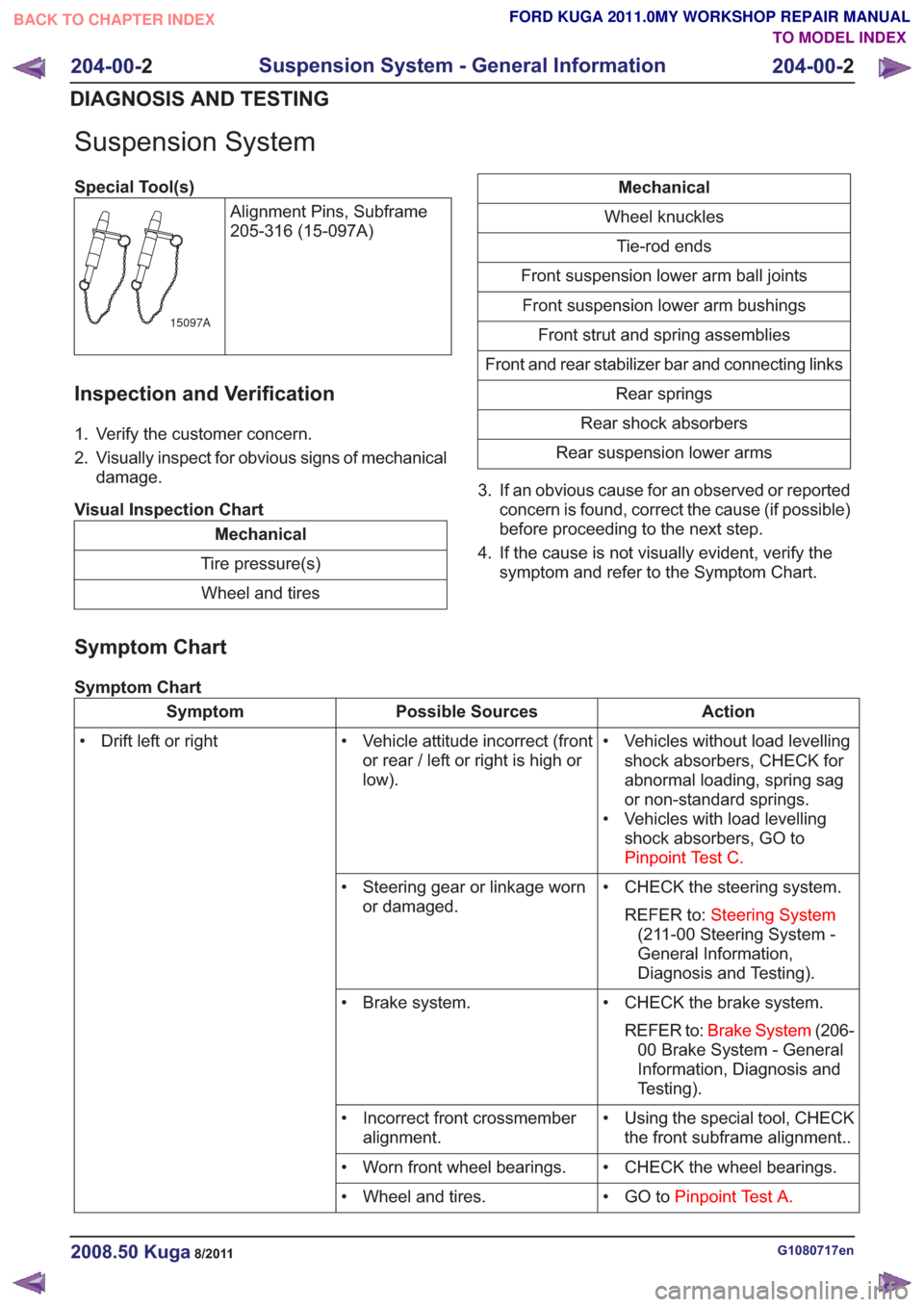
Suspension System
Special Tool(s)Alignment Pins, Subframe
205-316 (15-097A)
15097A
Inspection and Verification
1. Verify the customer concern.
2. Visually inspect for obvious signs of mechanicaldamage.
Visual Inspection Chart
Mechanical
Tire pressure(s) Wheel and tires
Mechanical
Wheel knuckles Tie-rod ends
Front suspension lower arm ball joints Front suspension lower arm bushings Front strut and spring assemblies
Front and rear stabilizer bar and connecting links Rear springs
Rear shock absorbers
Rear suspension lower arms
3. If an obvious cause for an observed or reported concern is found, correct the cause (if possible)
before proceeding to the next step.
4. If the cause is not visually evident, verify the symptom and refer to the Symptom Chart.
Symptom Chart
Symptom Chart
Action
Possible Sources
Symptom
• Vehicles without load levellingshock absorbers, CHECK for
abnormal loading, spring sag
or non-standard springs.
• Vehicles with load levelling shock absorbers, GO to
Pinpoint Test C.
• Vehicle attitude incorrect (front
or rear / left or right is high or
low).
• Drift left or right
• CHECK the steering system.REFER to: Steering System
(211-00 Steering System -
General Information,
Diagnosis and Testing).
• Steering gear or linkage worn
or damaged.
• CHECK the brake system.REFER to: Brake System (206-
00 Brake System - General
Information, Diagnosis and
Testing).
• Brake system.
• Using the special tool, CHECKthe front subframe alignment..
• Incorrect front crossmember
alignment.
• CHECK the wheel bearings.
• Worn front wheel bearings.
• GO toPinpoint Test A.
• Wheel and tires.
G1080717en2008.50 Kuga8/2011
204-00- 2
Suspension System - General Information
204-00- 2
DIAGNOSIS AND TESTING
TO MODEL INDEX
BACK TO CHAPTER INDEX
FORD KUGA 2011.0MY WORKSHOP REPAIR MANUAL
Page 363 of 2057

Front Fog Lamp Adjustment
General Equipment
Headlamp Beam Setter
Activation
1. Place the vehicle on a level surface.
2. Ensure that the tire pressures are to
specification and that the vehicle is not
overloaded.
3. Switch on the front fog lamps.
4. Set the measuring screen of the beam setting
equipment to the correct front fog lamp
adjustment setting.
Refer to: Specifications (417-01 Exterior
Lighting, Specifications).
General Equipment: Headlamp Beam Setter
5. Adjust the fog lamp so that the cut-off line
touches the horizontal line. G1066056en
2008.50 Kuga 8/2011 417-01-29
Exterior Lighting
417-01-29
GENERAL PROCEDURESTO MODEL INDEX
BACK TO CHAPTER INDEX
FORD KUGA 2011.0MY WORKSHOP REPAIR MANUALE11721815
Page 364 of 2057

Headlamp Adjustment
General Equipment
Headlamp Beam Setter
All Vehicles
1. NOTE: Make sure that the tire pressures are to
specification and that the vehicle is unladen.
NOTE: Only use a damp cloth to clean the
headlamp lens to avoid any electrostatic
charging.
Ensure that the adjustment is made with the
suspension set up.
2. Place the vehicle on a level surface.
Vehicles with conventional headlamps
3. Repeatedly operate the headlamp leveling
switch and then set it to "0".
Vehicles with adaptive front lighting
4. Use the diagnostic tool to make certain that the
front wheels are in the straight ahead position.
Vehicles with gas discharge headlamps
5. Calibrate the headlamp leveling system using
the diagnostic tool.
All Vehicles
6. NOTE: Always follow the manufacturer's
instructions when handling the equipment.
Set the measuring screen of the beam setting
equipment to the correct headlamp adjustment
setting.
Refer to: Specifications (417-01 Exterior
Lighting, Specifications).
General Equipment: Headlamp Beam Setter
7. Switch on dipped beam. 8.
Adjust the dipped beams so that the light/dark
boundary touches the horizontal line. 9. NOTE:
It is acceptable for a stray portion of the
low beam to cross the 15° line.
Adjust the headlamps so that the rising line of
the boundary line lies at the intersection of G1066055en
2008.50 Kuga 8/2011 417-01-30
Exterior Lighting
417-01-30
GENERAL PROCEDURESTO MODEL INDEX
BACK TO CHAPTER INDEX
FORD KUGA 2011.0MY WORKSHOP REPAIR MANUALE11721715
Page 1228 of 2057

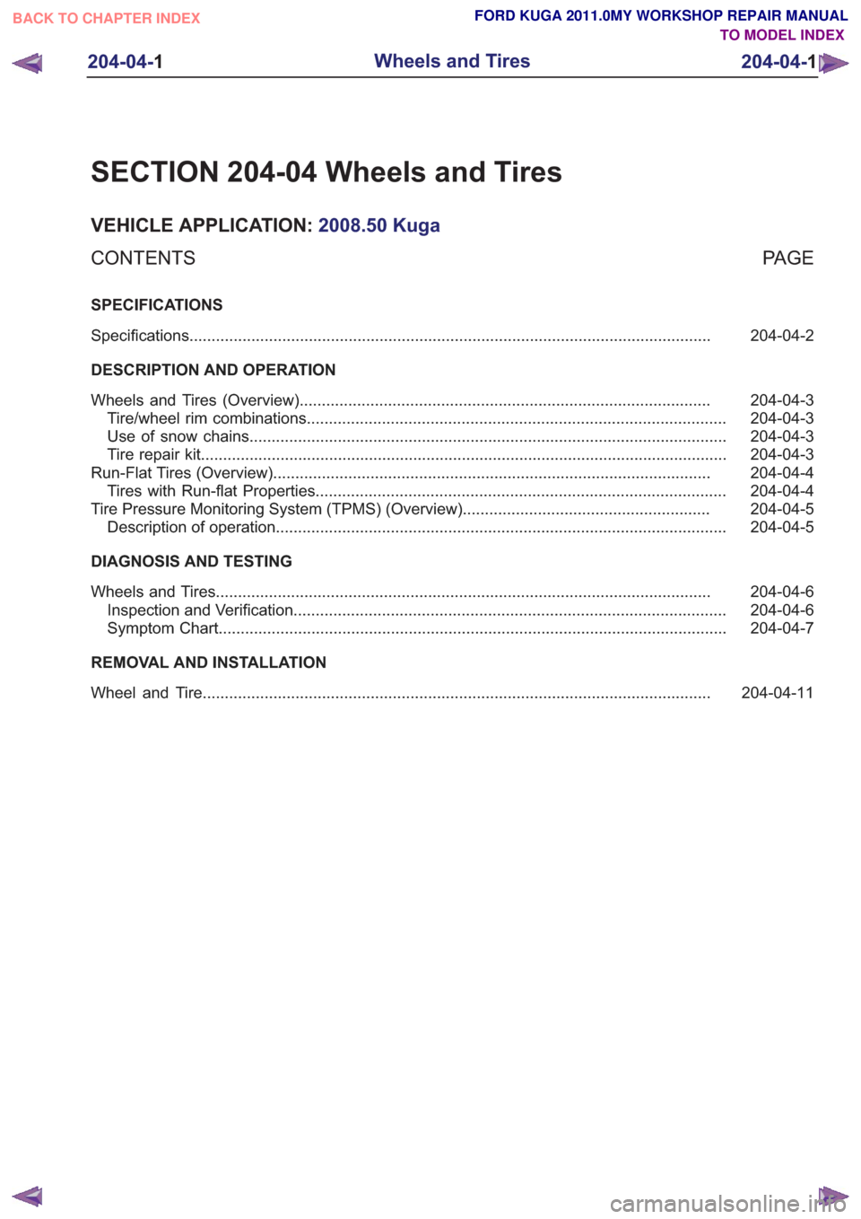
SECTION 204-04 Wheels and Tires
VEHICLE APPLICATION:2008.50 Kuga
PA G E
CONTENTS
SPECIFICATIONS
204-04-2
Specifications ........................................................................\
..............................................
DESCRIPTION AND OPERATION 204-04-3
Wheels and Tires (Overview) ........................................................................\
.....................
204-04-3
Tire/wheel rim combinations ........................................................................\
.......................
204-04-3
Use of snow chains ........................................................................\
....................................
204-04-3
Tire repair kit ........................................................................\
...............................................
204-04-4
Run-Flat Tires (Overview) ........................................................................\
...........................
204-04-4
Tires with Run-flat Properties ........................................................................\
.....................
204-04-5
Tire Pressure Monitoring System (TPMS) (Overview) ........................................................
204-04-5
Description of operation ........................................................................\
..............................
DIAGNOSIS AND TESTING 204-04-6
Wheels and Tires ........................................................................\
........................................
204-04-6
Inspection and Verification ........................................................................\
..........................
204-04-7
Symptom Chart ........................................................................\
...........................................
REMOVAL AND INSTALLATION 204-04-11
Wheel and Tire........................................................................\
...........................................
204-04- 1
Wheels and Tires
204-04- 1
.
TO MODEL INDEX
BACK TO CHAPTER INDEX
FORD KUGA 2011.0MY WORKSHOP REPAIR MANUAL
Page 1229 of 2057

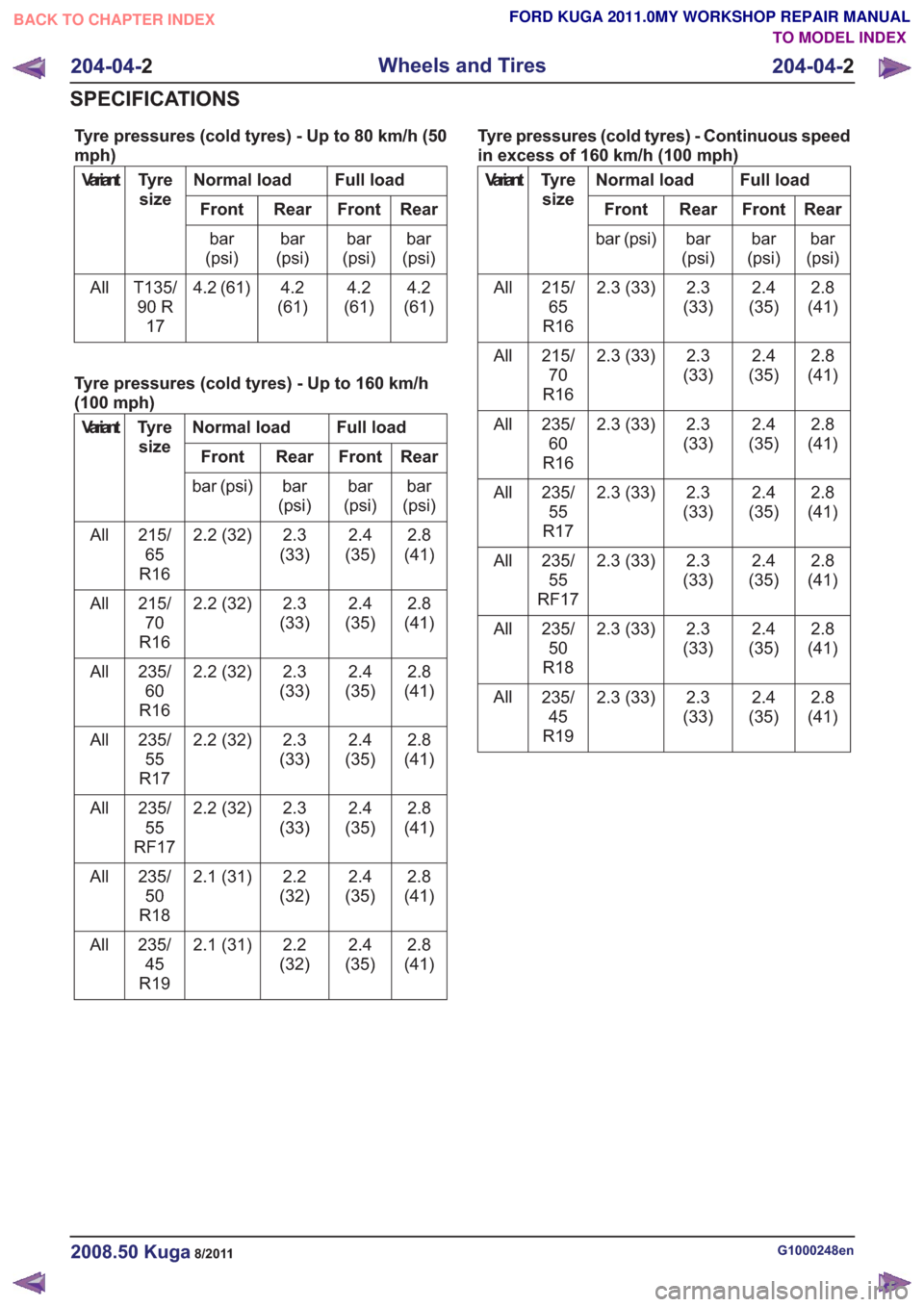
Tyre pressures (cold tyres) - Up to 80 km/h (50
mph)
Full load
Normal load
Tyre
size
Variant
Rear
Front
Rear
Front
bar
(psi)
bar
(psi)
bar
(psi)
bar
(psi)
4.2
(61)
4.2
(61)
4.2
(61)
4.2 (61)
T135/
90 R 17
All
Tyre pressures (cold tyres) - Up to 160 km/h
(100 mph)
Full load
Normal load
Tyre
size
Variant
Rear
Front
Rear
Front
bar
(psi)
bar
(psi)
bar
(psi)
bar (psi)
2.8
(41)
2.4
(35)
2.3
(33)
2.2 (32)
215/
65
R16
All
2.8
(41)
2.4
(35)
2.3
(33)
2.2 (32)
215/
70
R16
All
2.8
(41)
2.4
(35)
2.3
(33)
2.2 (32)
235/
60
R16
All
2.8
(41)
2.4
(35)
2.3
(33)
2.2 (32)
235/
55
R17
All
2.8
(41)
2.4
(35)
2.3
(33)
2.2 (32)
235/
55
RF17
All
2.8
(41)
2.4
(35)
2.2
(32)
2.1 (31)
235/
50
R18
All
2.8
(41)
2.4
(35)
2.2
(32)
2.1 (31)
235/
45
R19
All Tyre pressures (cold tyres) - Continuous speed
in excess of 160 km/h (100 mph)
Full load
Normal load
Tyre
size
Variant
Rear
Front
Rear
Front
bar
(psi)
bar
(psi)
bar
(psi)
bar (psi)
2.8
(41)
2.4
(35)
2.3
(33)
2.3 (33)
215/
65
R16
All
2.8
(41)
2.4
(35)
2.3
(33)
2.3 (33)
215/
70
R16
All
2.8
(41)
2.4
(35)
2.3
(33)
2.3 (33)
235/
60
R16
All
2.8
(41)
2.4
(35)
2.3
(33)
2.3 (33)
235/
55
R17
All
2.8
(41)
2.4
(35)
2.3
(33)
2.3 (33)
235/
55
RF17
All
2.8
(41)
2.4
(35)
2.3
(33)
2.3 (33)
235/
50
R18
All
2.8
(41)
2.4
(35)
2.3
(33)
2.3 (33)
235/
45
R19
All
G1000248en2008.50 Kuga8/2011
204-04-
2
Wheels and Tires
204-04- 2
SPECIFICATIONS
TO MODEL INDEX
BACK TO CHAPTER INDEX
FORD KUGA 2011.0MY WORKSHOP REPAIR MANUAL