2011 FORD KUGA tire pressure
[x] Cancel search: tire pressurePage 1230 of 2057
Wheels and Tires – Overview
Tire/wheel rim combinations
The following tire/wheel rim combinations are
available:
• 235/60 R16 V – 6.5X16 (*)
• 235/55 R17 V – 7.0X17 (*)
• 235/55 R17 V – 7.5X17 (*)
• 235/50 R18 V – 7.5X18
• 235/45 R19 V – 8.0X19
(*) Also available as tires with run-flat capabilities.
Use of snow chains
Snow chains are only approved for use with size
235/60R16 tires.
Fine chains with a link thickness of 10mm may be
used at speeds of up to 50 km/h (please refer to
the manufacturer's instructions).
Coarser chains with a link thickness of 11 to 14
mm may be used at speeds of up to 40 km/h
(please refer to the manufacturer's instructions).
Tire repair kit
If the tires used do not have run-flat properties then
the vehicle will be equipped with a tire repair kit.
A tire repair kit is located in the spare wheel well
in the luggage compartment.
The tire repair kit consists of:
• a compressor with a pressure gauge,
• a lead for voltage supply via the cigar lighter,
• an air hose,
• tire sealant.
A tire filled with tire sealant must be replaced with
a new tire after 200 km at the latest. Read and
observe the instructions regarding the tire low
pressure sensors (see lesson 4 – Tire pressure
monitoring system).
Instructions on handling and using the tire repair
kit can be found in a separate operating manual
that is enclosed with the tire repair kit.
G1000249en2008.50 Kuga8/2011
204-04-3
Wheels and Tires
204-04- 3
DESCRIPTION AND OPERATION
TO MODEL INDEX
BACK TO CHAPTER INDEX
FORD KUGA 2011.0MY WORKSHOP REPAIR MANUAL
Page 1231 of 2057
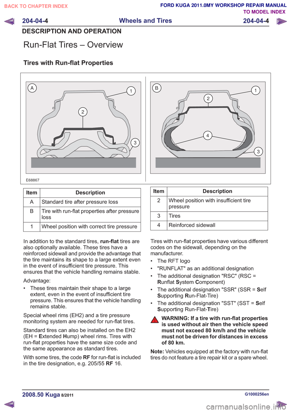
Run-Flat Tires – Overview
Tires with Run-flat Properties
E68867
2
1
3
2
4
1
3
BA
Description
Item
Standard tire after pressure loss
A
Tire with run-flat properties after pressure
loss
B
Wheel position with correct tire pressure
1Description
Item
Wheel position with insufficient tire
pressure
2
Tires
3
Reinforced sidewall
4
In addition to the standard tires, run-flattires are
also optionally available. These tires have a
reinforced sidewall and provide the advantage that
the tire maintains its shape to a large extent even
in the event of insufficient tire pressure. This
ensures that the vehicle handling remains stable.
Advantage:
• These tires maintain their shape to a large extent, even in the event of insufficient tire
pressure. This ensures that the vehicle handling
remains stable.
Special wheel rims (EH2) and a tire pressure
monitoring system are needed for run-flat tires.
Standard tires can also be installed on the EH2
(EH = Extended Hump) wheel rims. Tires with
run-flat properties have the same size code and
the same appearance as standard tires.
With some tires, the code RFfor run-flat is included
in the tire designation, e.g. 205/55 RF16. Tires with run-flat properties have various different
codes on the sidewall, depending on the
manufacturer.
• The RFT logo
• "RUNFLAT" as an additional designation
• The additional designation "RSC" (RSC =
Runflat System Component)
• The additional designation "SSR" (SSR = Self
S upporting Run-Flat-Tire)
• The additional designation "SST" (SST = Self
S upporting Run-Flat- Tire)
WARNING: If a tire with run-flat properties
is used without air then the vehicle speed
must not exceed 80 km/h and the vehicle
must not be driven for distances in excess
of 80 km.
Note: Vehicles equipped at the factory with run-flat
tires do not feature a tire repair kit or a spare wheel.
G1000256en2008.50 Kuga8/2011
204-04- 4
Wheels and Tires
204-04- 4
DESCRIPTION AND OPERATION
TO MODEL INDEX
BACK TO CHAPTER INDEX
FORD KUGA 2011.0MY WORKSHOP REPAIR MANUAL
Page 1232 of 2057
Tire Pressure Monitoring System (TPMS) – Overview
Description of operation
The tire pressure monitoring system is able to
detect loss of air in a tire at an early stage and warn
the driver. Because it can only compare the
behavior of the tires with each other, it is not
possible to draw conclusions about the absolute
tire pressure. It is also not possible to monitor the
spare tire pressure. In order for the system to
operate correctly, the tire pressures must be
regularly checked and corrected and the system
subsequently initialized (see below).
The tire pressure monitoring system used here,
depending on the equipment level, is built into the
anti-lock braking system (ABS) as an extra function
and therefore does not have its own sensors.
The ABS module determines the loss of pressure
in the tires by calculation using the wheel speed
sensors of the ABS system. If a tire loses pressure,
its diameter decreases and the speed of the wheel
therefore increases. If the ABS module detects
such a loss in pressure, it sends a signal to the
instrument cluster via the CAN bus and a warning
message is displayed in the driver information
system. The warning threshold depends among
other things on the dimension of the tires being
used, the vehicle operating conditions and the
status at the last initialization. Since neither the
absolute tire pressure nor the position of the tire is
known, after a tire pressure warning the pressure
of all the tires must be checked and the system
re-initialized. If necessary, the cause of the loss of
pressure must be investigated.
Furthermore, regular pressure checks are
necessary. The system must be initialized after a
tire is changed, winter or summer tires fitted, the
pressures corrected or adjusted to suit the vehicle
load. This can be done by the driver using the
driver information system. For further information,
see: Owner’s Manual.
G1001290en2008.50 Kuga8/2011
204-04-5
Wheels and Tires
204-04- 5
DESCRIPTION AND OPERATION
TO MODEL INDEX
BACK TO CHAPTER INDEX
FORD KUGA 2011.0MY WORKSHOP REPAIR MANUAL
Page 1233 of 2057
Wheels and Tires
Inspection and Verification
Visual Inspection Chart
MechanicalWheel(s)Tire(s)
Tire pressure(s) * Wheel nuts
Wheel studs
* Vehicles equipped with a tire deflation detection system (DDS) must be inspected for correct operation using the Ford approved diagnostic tool.
To maximize tire performance, inspect the tires for
signs of incorrect inflation and uneven wear which
may indicate a need for balancing, rotation or
suspension alignment. Tires should also be
checked frequently for cuts, stone bruises,
abrasions, blisters and for objects that may have
become embedded in the tread. More frequent
inspections are recommended when rapid or
extreme temperature changes occur or when road
surfaces are rough or occasionally littered with
foreign material.
As a further visible check of tire condition, tread
wear indicators are molded into the bottom of the
tread grooves. When these indicator bands become
visible, new tires must be installed.
Tire Wear Diagnosis
Uneven wear is usually caused by either excessive
camber or excessive toe on tires.
Sometimes incorrect toe settings or worn struts will
cause severe `cupping' or `scalloped' tire wear on
non-driven wheels.
Severely incorrect toe settings will also cause other
unusual wear patterns.
Tire Vibration Diagnosis
A tire vibration diagnostic procedure always begins
with a road test. The road test and customer
interview (if available) will provide much of the
information needed to find the source of a vibration. During the road test, drive the vehicle on a road
that is smooth and free of undulations. If vibration
is apparent, note and record the following:
– the speed at which the vibration occurs.
– what type of vibration occurs in each speed
range.
– mechanical or audible
– how the vibration is affected by changes in the following:
– engine torque
– vehicle speed
– engine speed
– type of vibration - sensitivity: – torque sensitive
– vehicle speed sensitive
– engine speed sensitive
The following explanations help isolate the source
of the vibration.
Torque Sensitive
This means that the condition can be improved or
made worse by accelerating, decelerating,
coasting, maintaining a steady vehicle speed or
applying engine torque.
Vehicle Speed Sensitive
This means that the vibration always occurs at the
same vehicle speed and is not affected by engine
torque, engine speed or the transmission gear
selected.
G1061329en2008.50 Kuga8/2011
204-04- 6
Wheels and Tires
204-04- 6
DIAGNOSIS AND TESTING
TO MODEL INDEX
BACK TO CHAPTER INDEX
FORD KUGA 2011.0MY WORKSHOP REPAIR MANUAL
Page 1234 of 2057
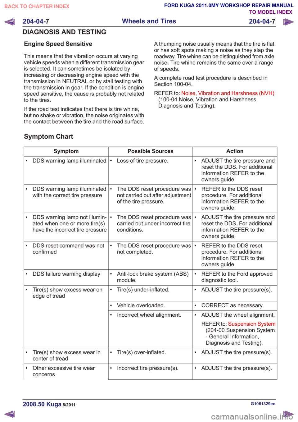
Engine Speed Sensitive
This means that the vibration occurs at varying
vehicle speeds when a different transmission gear
is selected. It can sometimes be isolated by
increasing or decreasing engine speed with the
transmission in NEUTRAL or by stall testing with
the transmission in gear. If the condition is engine
speed sensitive, the cause is probably not related
to the tires.
If the road test indicates that there is tire whine,
but no shake or vibration, the noise originates with
the contact between the tire and the road surface.A thumping noise usually means that the tire is flat
or has soft spots making a noise as they slap the
roadway. Tire whine can be distinguished from axle
noise. Tire whine remains the same over a range
of speeds.
A complete road test procedure is described in
Section 100-04.
REFER to:
Noise, Vibration and Harshness (NVH)
(100-04 Noise, Vibration and Harshness,
Diagnosis and Testing).
Symptom Chart
Action
Possible Sources
Symptom
• ADJUST the tire pressure andreset the DDS. For additional
information REFER to the
owners guide.
• Loss of tire pressure.
• DDS warning lamp illuminated
• REFER to the DDS resetprocedure. For additional
information REFER to the
owners guide.
• The DDS reset procedure was
not carried out after adjustment
of the tire pressure.
• DDS warning lamp illuminated
with the correct tire pressure
• ADJUST the tire pressure andreset the DDS. For additional
information REFER to the
owners guide.
• The DDS reset procedure was
carried out under incorrect tire
conditions.
• DDS warning lamp not illumin-
ated when one or more tire(s)
have the incorrect tire pressure
• REFER to the DDS resetprocedure. For additional
information REFER to the
owners guide.
• The DDS reset procedure was
not completed.
• DDS reset command was not
confirmed
• REFER to the Ford approveddiagnostic tool.
• Anti-lock brake system (ABS)
module.
• DDS failure warning display
• ADJUST the tire pressure(s).
• Tire(s) under-inflated.
• Tire(s) show excess wear on
edge of tread
• CORRECT as necessary.
• Vehicle overloaded.
• ADJUST the wheel alignment.REFER to: Suspension System
(204-00 Suspension System
- General Information,
Diagnosis and Testing).
• Incorrect wheel alignment.
• ADJUST the tire pressure(s).
• Tire(s) over-inflated.
• Tire(s) show excess wear in
center of tread
• ADJUST the tire pressure(s).
• Incorrect tire pressure(s).
• Other excessive tire wear
concerns
G1061329en2008.50 Kuga8/2011
204-04- 7
Wheels and Tires
204-04- 7
DIAGNOSIS AND TESTING
TO MODEL INDEX
BACK TO CHAPTER INDEX
FORD KUGA 2011.0MY WORKSHOP REPAIR MANUAL
Page 1236 of 2057
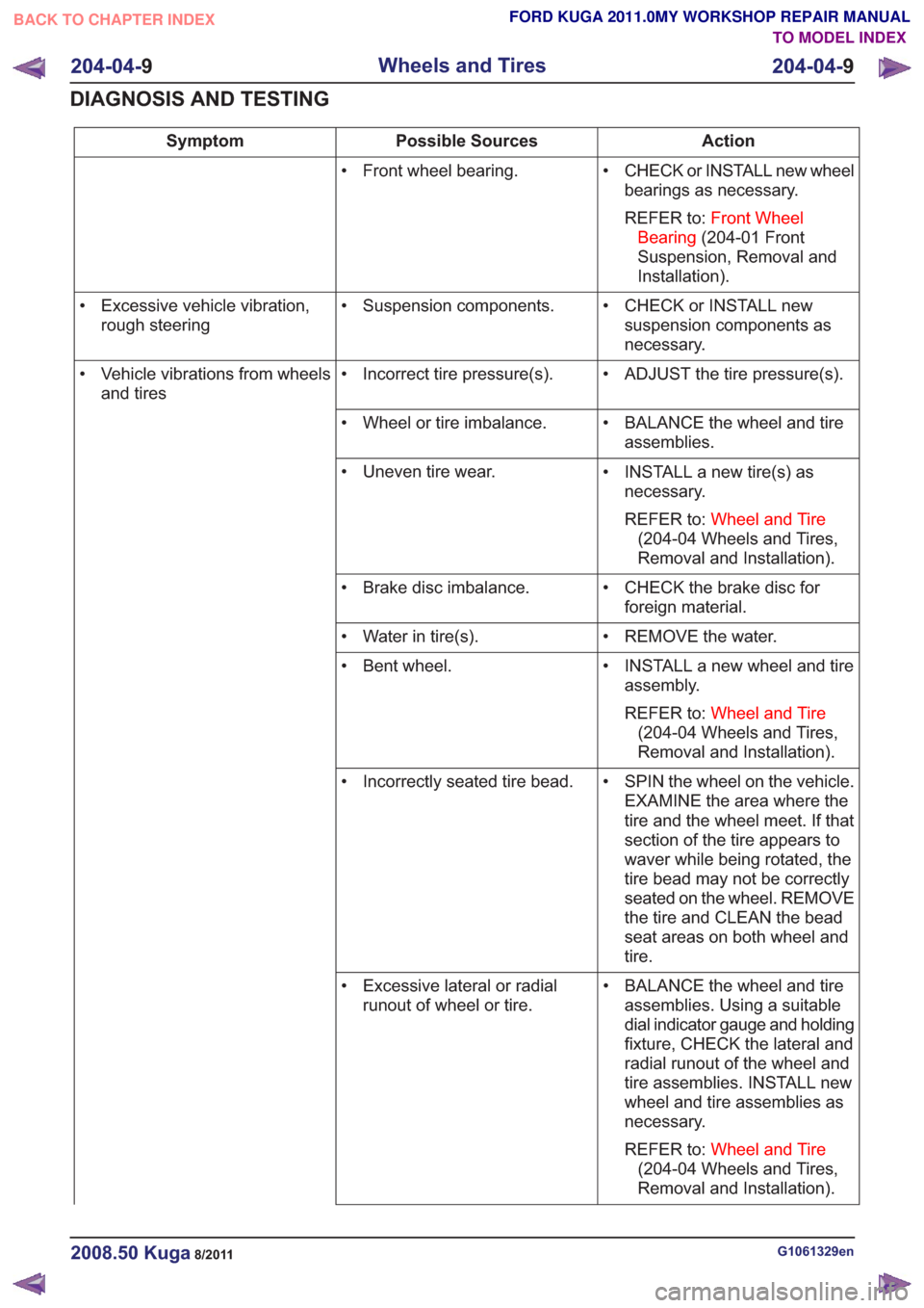
Action
Possible Sources
Symptom
• CHECK or INSTALL new wheelbearings as necessary.
REFER to: Front Wheel
Bearing (204-01 Front
Suspension, Removal and
Installation).
• Front wheel bearing.
• CHECK or INSTALL newsuspension components as
necessary.
• Suspension components.
• Excessive vehicle vibration,
rough steering
• ADJUST the tire pressure(s).
• Incorrect tire pressure(s).
• Vehicle vibrations from wheels
and tires
• BALANCE the wheel and tireassemblies.
• Wheel or tire imbalance.
• INSTALL a new tire(s) asnecessary.
REFER to: Wheel and Tire
(204-04 Wheels and Tires,
Removal and Installation).
• Uneven tire wear.
• CHECK the brake disc forforeign material.
• Brake disc imbalance.
• REMOVE the water.
• Water in tire(s).
• INSTALL a new wheel and tireassembly.
REFER to: Wheel and Tire
(204-04 Wheels and Tires,
Removal and Installation).
• Bent wheel.
• SPIN the wheel on the vehicle.EXAMINE the area where the
tire and the wheel meet. If that
section of the tire appears to
waver while being rotated, the
tire bead may not be correctly
seated on the wheel. REMOVE
the tire and CLEAN the bead
seat areas on both wheel and
tire.
• Incorrectly seated tire bead.
• BALANCE the wheel and tireassemblies. Using a suitable
dial indicator gauge and holding
fixture, CHECK the lateral and
radial runout of the wheel and
tire assemblies. INSTALL new
wheel and tire assemblies as
necessary.
REFER to: Wheel and Tire
(204-04 Wheels and Tires,
Removal and Installation).
• Excessive lateral or radial
runout of wheel or tire.
G1061329en2008.50 Kuga8/2011
204-04- 9
Wheels and Tires
204-04- 9
DIAGNOSIS AND TESTING
TO MODEL INDEX
BACK TO CHAPTER INDEX
FORD KUGA 2011.0MY WORKSHOP REPAIR MANUAL
Page 1340 of 2057
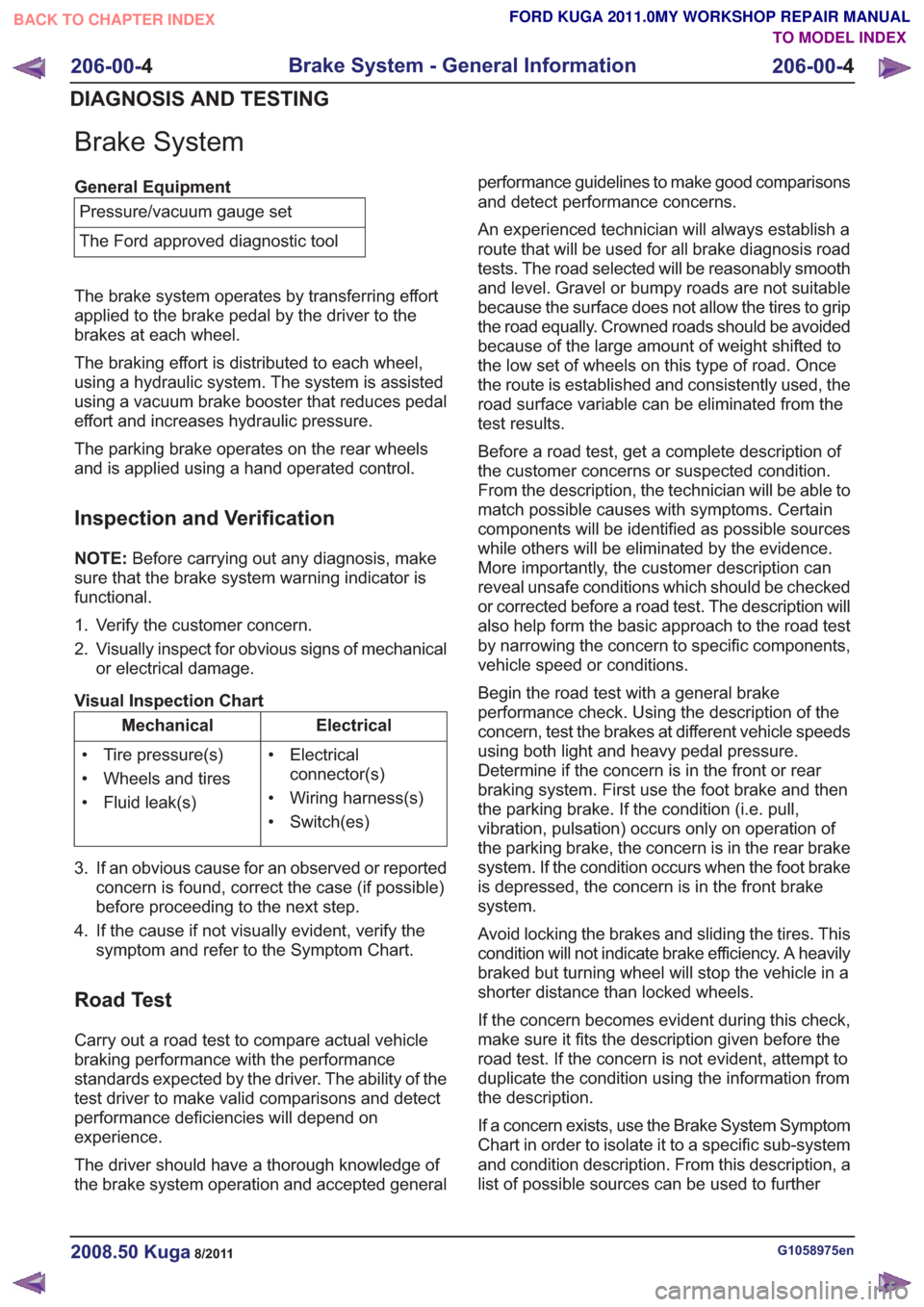
Brake System
General EquipmentPressure/vacuum gauge set
The Ford approved diagnostic tool
The brake system operates by transferring effort
applied to the brake pedal by the driver to the
brakes at each wheel.
The braking effort is distributed to each wheel,
using a hydraulic system. The system is assisted
using a vacuum brake booster that reduces pedal
effort and increases hydraulic pressure.
The parking brake operates on the rear wheels
and is applied using a hand operated control.
Inspection and Verification
NOTE: Before carrying out any diagnosis, make
sure that the brake system warning indicator is
functional.
1. Verify the customer concern.
2. Visually inspect for obvious signs of mechanical or electrical damage.
Visual Inspection Chart
Electrical
Mechanical
• Electricalconnector(s)
• Wiring harness(s)
• Switch(es)
• Tire pressure(s)
• Wheels and tires
• Fluid leak(s)
3. If an obvious cause for an observed or reported concern is found, correct the case (if possible)
before proceeding to the next step.
4. If the cause if not visually evident, verify the symptom and refer to the Symptom Chart.
Road Test
Carry out a road test to compare actual vehicle
braking performance with the performance
standards expected by the driver. The ability of the
test driver to make valid comparisons and detect
performance deficiencies will depend on
experience.
The driver should have a thorough knowledge of
the brake system operation and accepted general performance guidelines to make good comparisons
and detect performance concerns.
An experienced technician will always establish a
route that will be used for all brake diagnosis road
tests. The road selected will be reasonably smooth
and level. Gravel or bumpy roads are not suitable
because the surface does not allow the tires to grip
the road equally. Crowned roads should be avoided
because of the large amount of weight shifted to
the low set of wheels on this type of road. Once
the route is established and consistently used, the
road surface variable can be eliminated from the
test results.
Before a road test, get a complete description of
the customer concerns or suspected condition.
From the description, the technician will be able to
match possible causes with symptoms. Certain
components will be identified as possible sources
while others will be eliminated by the evidence.
More importantly, the customer description can
reveal unsafe conditions which should be checked
or corrected before a road test. The description will
also help form the basic approach to the road test
by narrowing the concern to specific components,
vehicle speed or conditions.
Begin the road test with a general brake
performance check. Using the description of the
concern, test the brakes at different vehicle speeds
using both light and heavy pedal pressure.
Determine if the concern is in the front or rear
braking system. First use the foot brake and then
the parking brake. If the condition (i.e. pull,
vibration, pulsation) occurs only on operation of
the parking brake, the concern is in the rear brake
system. If the condition occurs when the foot brake
is depressed, the concern is in the front brake
system.
Avoid locking the brakes and sliding the tires. This
condition will not indicate brake efficiency. A heavily
braked but turning wheel will stop the vehicle in a
shorter distance than locked wheels.
If the concern becomes evident during this check,
make sure it fits the description given before the
road test. If the concern is not evident, attempt to
duplicate the condition using the information from
the description.
If a concern exists, use the Brake System Symptom
Chart in order to isolate it to a specific sub-system
and condition description. From this description, a
list of possible sources can be used to further
G1058975en2008.50 Kuga8/2011
206-00-
4
Brake System - General Information
206-00- 4
DIAGNOSIS AND TESTING
TO MODEL INDEX
BACK TO CHAPTER INDEX
FORD KUGA 2011.0MY WORKSHOP REPAIR MANUAL
Page 1343 of 2057
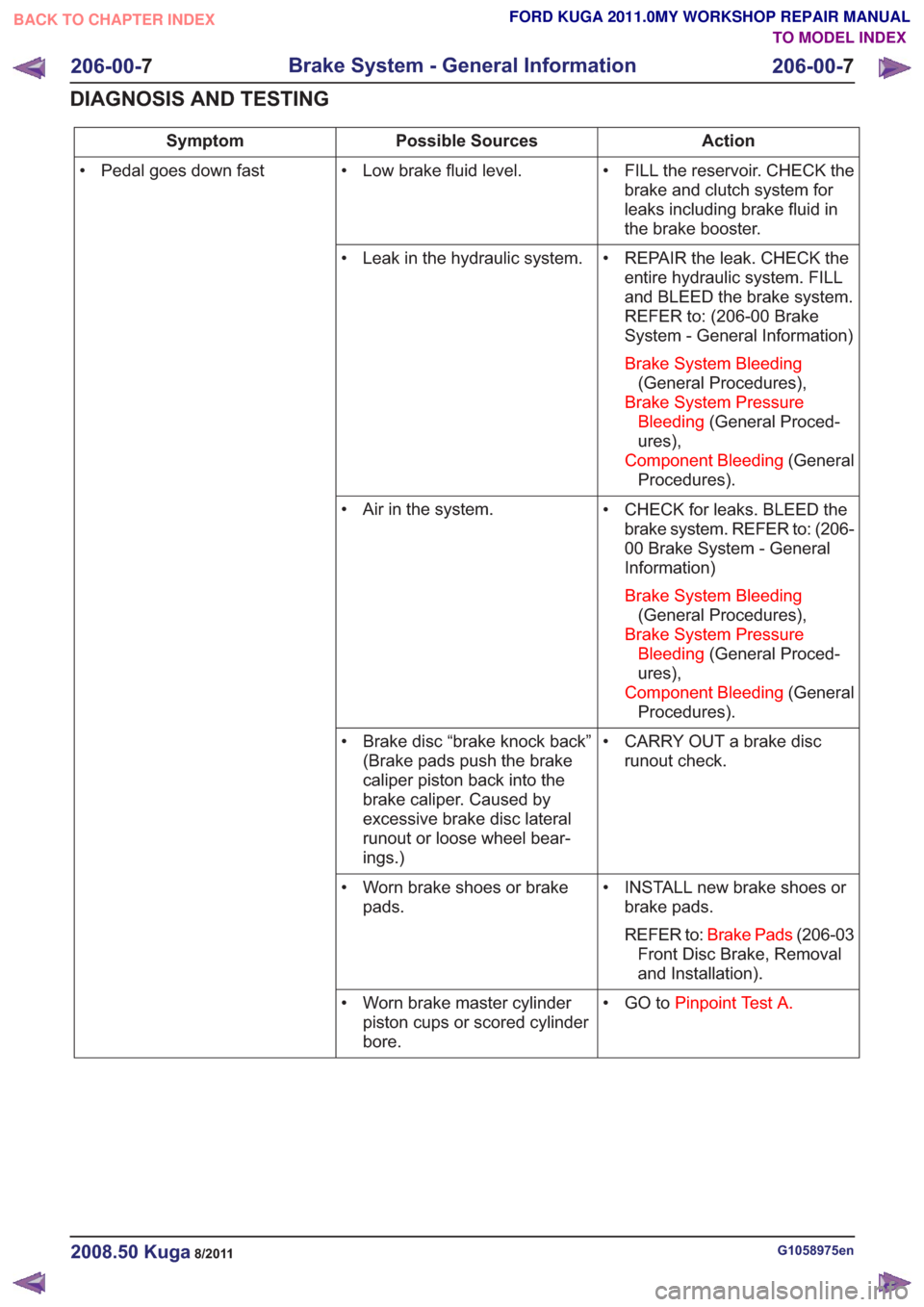
Action
Possible Sources
Symptom
• FILL the reservoir. CHECK thebrake and clutch system for
leaks including brake fluid in
the brake booster.
• Low brake fluid level.
• Pedal goes down fast
• REPAIR the leak. CHECK theentire hydraulic system. FILL
and BLEED the brake system.
REFER to: (206-00 Brake
System - General Information)
Brake System Bleeding (General Procedures),
Brake System Pressure Bleeding (General Proced-
ures),
Component Bleeding (General
Procedures).
• Leak in the hydraulic system.
• CHECK for leaks. BLEED thebrake system. REFER to: (206-
00 Brake System - General
Information)
Brake System Bleeding (General Procedures),
Brake System Pressure Bleeding (General Proced-
ures),
Component Bleeding (General
Procedures).
• Air in the system.
• CARRY OUT a brake discrunout check.
• Brake disc “brake knock back”
(Brake pads push the brake
caliper piston back into the
brake caliper. Caused by
excessive brake disc lateral
runout or loose wheel bear-
ings.)
• INSTALL new brake shoes orbrake pads.
REFER to: Brake Pads (206-03
Front Disc Brake, Removal
and Installation).
• Worn brake shoes or brake
pads.
• GO toPinpoint Test A.
• Worn brake master cylinder
piston cups or scored cylinder
bore.
G1058975en2008.50 Kuga8/2011
206-00- 7
Brake System - General Information
206-00- 7
DIAGNOSIS AND TESTING
TO MODEL INDEX
BACK TO CHAPTER INDEX
FORD KUGA 2011.0MY WORKSHOP REPAIR MANUAL