Page 1176 of 2057

Description
Item
Stabilizer bar bushes and bracket
9Description
Item
10 Wheel hub
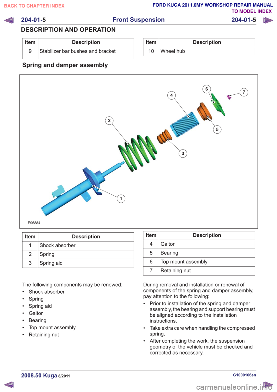
Spring and damper assembly
E96884
1
2
3
4
5
67
Description
Item
Shock absorber
1
Spring
2
Spring aid
3Description
Item
Gaitor
4
Bearing
5
Top mount assembly
6
Retaining nut
7
The following components may be renewed:
• Shock absorber
• Spring
• Spring aid
• Gaitor
• Bearing
• Top mount assembly
• Retaining nut During removal and installation or renewal of
components of the spring and damper assembly,
pay attention to the following:
• Prior to installation of the spring and damper
assembly, the bearing and support bearing must
be aligned according to the installation
instructions.
• Take extra care when handling the compressed spring.
• After completing the work, the suspension geometry of the vehicle must be checked and
corrected as necessary.
G1000166en2008.50 Kuga8/2011
204-01- 5
Front Suspension
204-01- 5
DESCRIPTION AND OPERATION
TO MODEL INDEX
BACK TO CHAPTER INDEX
FORD KUGA 2011.0MY WORKSHOP REPAIR MANUAL
Page 1178 of 2057
Stabilizer bar
E98611
1
2
3
Description
Item
Stabilizer bar
1
Bushes, stabilizer bar
2
Bracket, stabilizer bar bushes
3
The following components may be renewed:
• Stabilizer bar
• Bushes, stabilizer bar
• Bracket, stabilizer bar bushes
During removal and installation or renewal of
components of the stabilizer bar, pay attention to
the following:
• Before installing the stabilizer bar bushes, they must be aligned according to the installation
instructions.
• After completing the work, the suspension geometry of the vehicle must be checked and
corrected as necessary.
G1000166en2008.50 Kuga8/2011
204-01- 7
Front Suspension
204-01- 7
DESCRIPTION AND OPERATION
TO MODEL INDEX
BACK TO CHAPTER INDEX
FORD KUGA 2011.0MY WORKSHOP REPAIR MANUAL
Page 1207 of 2057
Stabilizer bar
E98611
1
2
3
Description
Item
Stabilizer bar
1
Bushes, stabilizer bar
2
Bracket, stabilizer bar bushes
3
The following components may be renewed:
• Stabilizer bar
• Bushes, stabilizer bar
• Bracket, stabilizer bar bushes
During removal and installation or renewal of
components of the stabilizer bar, pay attention to
the following:
• Before installing the stabilizer bar bushes, they must be aligned according to the installation
instructions.
G1000191en2008.50 Kuga8/2011
204-02- 5
Rear Suspension
204-02- 5
DESCRIPTION AND OPERATION
TO MODEL INDEX
BACK TO CHAPTER INDEX
FORD KUGA 2011.0MY WORKSHOP REPAIR MANUAL
Page 1297 of 2057

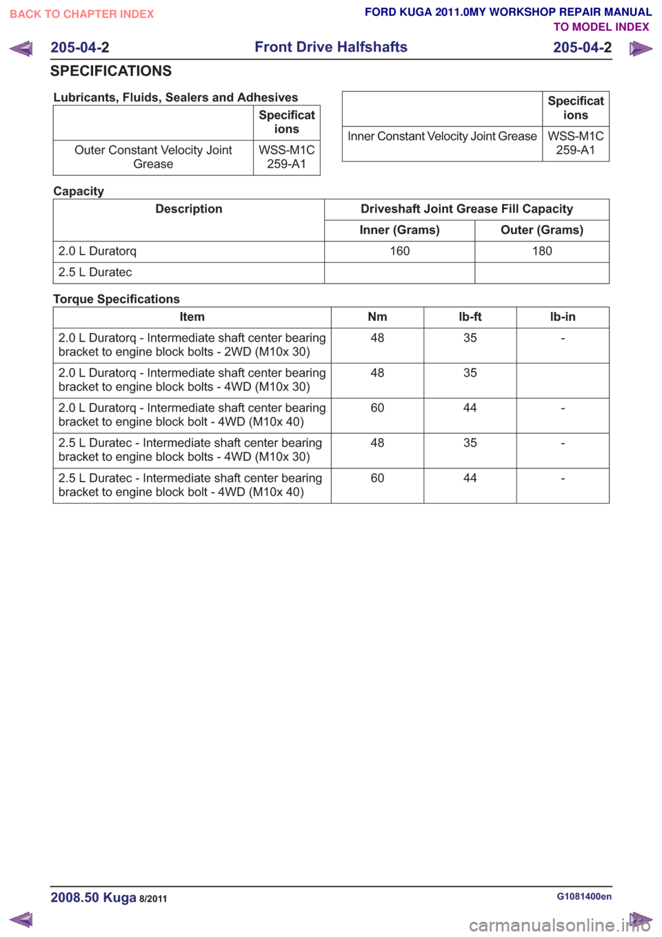
Lubricants, Fluids, Sealers and Adhesives
Specifications
WSS-M1C 259-A1
Outer Constant Velocity Joint
Grease
Specifications
WSS-M1C 259-A1
Inner Constant Velocity Joint Grease
Capacity
Driveshaft Joint Grease Fill Capacity
Description
Outer (Grams)
Inner (Grams)
180
160
2.0 L Duratorq
2.5 L Duratec
Torque Specifications
lb-in
lb-ft
Nm
Item
-
35
48
2.0 L Duratorq - Intermediate shaft center bearing
bracket to engine block bolts - 2WD (M10x 30)
35
48
2.0 L Duratorq - Intermediate shaft center bearing
bracket to engine block bolts - 4WD (M10x 30)
-
44
60
2.0 L Duratorq - Intermediate shaft center bearing
bracket to engine block bolt - 4WD (M10x 40)
-
35
48
2.5 L Duratec - Intermediate shaft center bearing
bracket to engine block bolts - 4WD (M10x 30)
-
44
60
2.5 L Duratec - Intermediate shaft center bearing
bracket to engine block bolt - 4WD (M10x 40)
G1081400en2008.50 Kuga8/2011
205-04- 2
Front Drive Halfshafts
205-04- 2
SPECIFICATIONS
TO MODEL INDEX
BACK TO CHAPTER INDEX
FORD KUGA 2011.0MY WORKSHOP REPAIR MANUAL
Page 1398 of 2057
SECTION 206-06 Hydraulic Brake Actuation
VEHICLE APPLICATION:2008.50 Kuga
PA G E
CONTENTS
REMOVAL AND INSTALLATION
206-06-2
Brake Pedal and Bracket — RHD 4WD/RHD FWD ...........................................................
206-06-5
(12 343 0)
Brake Master Cylinder — 2.5L Duratec (147kW/200PS) - VI5 .......................
206-06-1
Hydraulic Brake Actuation
206-06- 1
.
BACK TO CHAPTER INDEXFORD KUGA 2011.0MY WORKSHOP REPAIR MANUAL
TO MODEL INDEX
Page 1399 of 2057
Brake Pedal and Bracket — RHD 4WD/RHD FWD
Removal
NOTE:Removal steps in this procedure may
contain installation details.
Panel and Console, Removal and Installation).
2.
E101395
G1065459en2008.50 Kuga8/2011
206-06- 2
Hydraulic Brake Actuation
206-06- 2
REMOVAL AND INSTALLATION
BACK TO CHAPTER INDEXFORD KUGA 2011.0MY WORKSHOP REPAIR MANUAL
TO MODEL INDEX
1. Refer to: Floor Console Extension - Vehicles
With: Center Armrest (501-12 Instrument
Page 1422 of 2057

Description
Item
Front wheel sensor, right-hand side
8Description
Item
9 ESP switch
Testing the brakes on a roller dynamometer
- 4X4 vehicles only
On 4X4 vehicles a brake test on a roller
dynamometer must only be performed under the
following conditions.
• The brake test must not exceed a duration of 1 minute.
• Ignition key in position 0.
• The roller speed must not exceed 5 km/h.
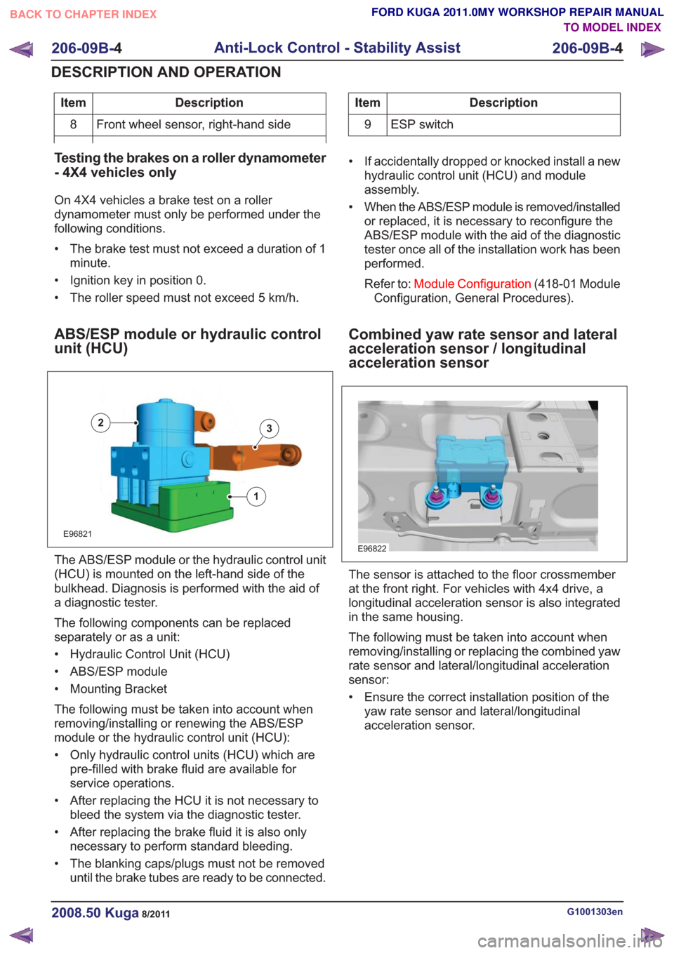
ABS/ESP module or hydraulic control
unit (HCU)
E96821
1
23
The ABS/ESP module or the hydraulic control unit
(HCU) is mounted on the left-hand side of the
bulkhead. Diagnosis is performed with the aid of
a diagnostic tester.
The following components can be replaced
separately or as a unit:
• Hydraulic Control Unit (HCU)
• ABS/ESP module
• Mounting Bracket
The following must be taken into account when
removing/installing or renewing the ABS/ESP
module or the hydraulic control unit (HCU):
• Only hydraulic control units (HCU) which are pre-filled with brake fluid are available for
service operations.
• After replacing the HCU it is not necessary to bleed the system via the diagnostic tester.
• After replacing the brake fluid it is also only necessary to perform standard bleeding.
• The blanking caps/plugs must not be removed until the brake tubes are ready to be connected. • If accidentally dropped or knocked install a new
hydraulic control unit (HCU) and module
assembly.
• When the ABS/ESP module is removed/installed or replaced, it is necessary to reconfigure the
ABS/ESP module with the aid of the diagnostic
tester once all of the installation work has been
performed.
Refer to: Module Configuration (418-01 Module
Configuration, General Procedures).
Combined yaw rate sensor and lateral
acceleration sensor / longitudinal
acceleration sensor
E96822
The sensor is attached to the floor crossmember
at the front right. For vehicles with 4x4 drive, a
longitudinal acceleration sensor is also integrated
in the same housing.
The following must be taken into account when
removing/installing or replacing the combined yaw
rate sensor and lateral/longitudinal acceleration
sensor:
• Ensure the correct installation position of the yaw rate sensor and lateral/longitudinal
acceleration sensor.
G1001303en2008.50 Kuga8/2011
206-09B- 4
Anti-Lock Control - Stability Assist
206-09B- 4
DESCRIPTION AND OPERATION
TO MODEL INDEX
BACK TO CHAPTER INDEX
FORD KUGA 2011.0MY WORKSHOP REPAIR MANUAL
Page 1462 of 2057
Electro-hydraulic power steering pump
E96414
1
2
3
4
5
3
Description
Item
Electro-hydraulic power steering pump
1
Cap, reservoir
2Description
Item
Rubber bushes, electro-hydraulic power
steering pump
3
Bracket #1
4
Bracket #2
5
The electro-hydraulic power steering pump is
mounted at the front right-hand side in the wheel
housing. The following components may be renewed:
• Electro-hydraulic power steering pump
• Cap, reservoir
G1001269en2008.50 Kuga8/2011
211-02-
5
Power Steering
211-02- 5
DESCRIPTION AND OPERATION
TO MODEL INDEX
BACK TO CHAPTER INDEX
FORD KUGA 2011.0MY WORKSHOP REPAIR MANUAL