2011 FORD F150 lock
[x] Cancel search: lockPage 219 of 461

Once the child safety seat has been installed using either the safety belt,
the lower anchors of the LATCH system, or both, you can attach the top
tether strap.
Front seat tether strap attachment (Regular cab)
1. Route the child safety seat tether strap over the back of the seat and
under the head restraint.
For vehicles with adjustable head restraints, route the tether strap under
the head restraint and between the head restraint posts, otherwise route
the tether strap over the top of the seatback.
2. Locate the correct anchor for the selected seating position.
•You may need to pull the seatback forward to access the tether
anchors. Make sure the seatback is locked in the upright position
before installing the child seat.
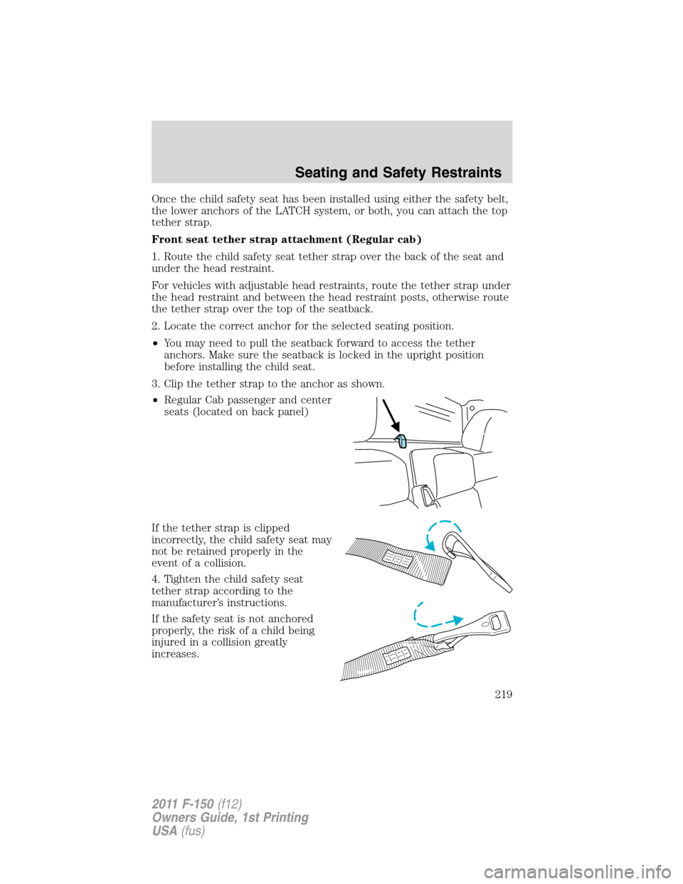
3. Clip the tether strap to the anchor as shown.
•Regular Cab passenger and center
seats (located on back panel)
If the tether strap is clipped
incorrectly, the child safety seat may
not be retained properly in the
event of a collision.
4. Tighten the child safety seat
tether strap according to the
manufacturer’s instructions.
If the safety seat is not anchored
properly, the risk of a child being
injured in a collision greatly
increases.
Seating and Safety Restraints
219
2011 F-150(f12)
Owners Guide, 1st Printing
USA(fus)
Page 249 of 461

3. Cycle the ignition to the on
position with the engine off.
4. Turn the hazard flashers on then
off three times. This must be
accomplished within 10 seconds.
If the reset mode has been entered successfully, the horn will sound
once, the TPMS indicator
will flash and the message center (if
equipped) will displayTRAIN LEFT FRONT TIRE. If this does not
occur, please try again starting at Step 2.
If after repeated attempts to enter the reset mode, the horn does not
sound, the TPMS indicator
does not flash and the message center (if
equipped) does not displayTRAIN LEFT FRONT TIRE, seek service
from your authorized dealer.
5. Train the TPMS sensors in the tires using the following TPMS reset
sequence starting with theleft front tirein the following clockwise
order:
•Left front (Driver’s side front tire)
•Right front (Passenger’s side front tire)
•Right rear (Passenger’s side rear tire)
•Left rear (Driver’s side rear tire)
6. Remove the valve cap from the valve stem on the left front tire;
decrease the air pressure until the horn sounds.
Note:The single horn chirp confirms that the sensor identification code
has been learned by the module for this position. If a double horn is
heard, the reset procedure was unsuccessful, and must be repeated.
7. Remove the valve cap from the valve stem on the right front tire;
decrease the air pressure until the horn sounds.
Tires, Wheels and Loading
249
2011 F-150(f12)
Owners Guide, 1st Printing
USA(fus)
Page 266 of 461

manual activation without a trailer connected or when gain
adjustments are made with no trailer connected.
•TBC GAIN = XX.X OUTPUT = //////:When the vehicle’s brake pedal
is pushed, or when the manual control is activated, bar indicators
illuminate in the instrument cluster message center to indicate the
amount of power going to the trailer brakes relative to the brake pedal
or manual control input. One bar indicates the least amount of output
with six bars indicating maximum output.
•TRAILER CONNECTED:This message is displayed when a correct
trailer wiring connection (a trailer with electric trailer brakes) has
been sensed during a given ignition cycle.
•TRAILER DISCONNECTED:This message is displayed and
accompanied by a single chime, when a trailer connection was
determined and then a disconnection, either intentionally or
unintentionally, has been sensed during a given ignition cycle. It is also
displayed if a truck or trailer wiring fault occurs causing the trailer to
appear disconnected. This message is also displayed during manual
activation without a trailer connected.
2.Manual control lever:Slide the control lever to the left to activate
power to the trailer’s electric brakes independent of the tow vehicle’s
brakes (see the followingProcedure for adjusting GAINsection for
instructions on proper use of this feature). If the manual control is
activated while the brake is also applied, the greater of the two inputs
determines the power sent to the trailer brakes.
•Stop lamps:Activating the TBC manual control lever illuminates both
the trailer brake lamps and the tow vehicle brake lamps except the
center high-mount stop lamp (presuming proper trailer electrical
connection). Pressing the vehicle brake pedal also illuminates both
trailer and vehicle brake lamps.
Procedure for adjusting GAIN:
The GAIN setting is used to set the TBC for the specific towing
condition and should be changed as towing conditions change. Changes
to towing conditions include trailer load, vehicle load, road conditions
and weather.
The GAIN should be set to provide the maximum trailer braking
assistance while ensuring the trailer wheels do not lock when braking;
locked trailer wheels may lead to trailer instability.
Note:This should only be performed in a traffic-free environment at
speeds of approximately 20–25 mph (30–40 km/h).
Tires, Wheels and Loading
266
2011 F-150(f12)
Owners Guide, 1st Printing
USA(fus)
Page 267 of 461

1. Make sure the trailer brakes are in good working condition,
functioning normally and properly adjusted. See your trailer dealer if
necessary.
2. Hook up the trailer and make the electrical connections according to
the trailer manufacturer’s instructions.
3. When a trailer with electric brakes is plugged in, theTRAILER
CONNECTEDmessage displays in the instrument cluster message
center.
4. Use the GAIN adjustment (+/-) buttons to increase or decrease the
GAIN setting to the desired starting point. A GAIN setting of 6.0 is a
good starting point for heavier loads.
5. In a traffic-free environment, tow the trailer on a dry, level surface at
a speed of 20–25 mph (30–40 km/h) and squeeze the manual control
lever completely.
6. If the trailer wheels lock up (indicated by squealing tires), reduce the
GAIN setting; if the trailer wheels turn freely, increase the GAIN setting.
Repeat Steps 5 and 6 until the GAIN setting is at a point just below
trailer wheel lock-up. If towing a heavier trailer, trailer wheel lock-up
may not be attainable even with the maximum GAIN setting of 10.
Explanation of instrument cluster warning messages:
The TBC interacts with the instrument cluster message center to display
the following messages:
TRAILER BRAKE MODULE FAULT:This message is displayed and
accompanied by a single chime, in response to faults sensed by the TBC.
In the event this message is seen, please contact your authorized dealer
as soon as possible for diagnosis and repair. The TBC may still function,
but performance may be degraded.
WIRING FAULT ON TRAILER:This message is displayed when a
Short circuit on the electric brake output wirehas occurred. If the
WIRING FAULT ON TRAILERmessage is displayed and accompanied
by a single chime, with no trailer connected, the problem is with the
vehicle wiring from the TBC to the 7–pin connector at the bumper. If the
message is only displayed with a trailer connected, the problem is related
to the trailer wiring; consult your trailer dealer for assistance. This can
be a short to ground (i.e., chaffed wire) or a short to voltage (i.e., pulled
pin on trailer emergency break-away battery) or trailer brakes drawing
too much current.
Note:Your TBC can be diagnosed by your authorized dealer to
determine exactly which trailer fault has occurred; however, if the fault
is with the trailer this diagnosis isnotcovered under your Ford
warranty.
Tires, Wheels and Loading
267
2011 F-150(f12)
Owners Guide, 1st Printing
USA(fus)
Page 268 of 461

Points to Remember:
•Remember to adjust gain setting before using the TBC for the first
time.
•Readjust gain setting on the TBC (according to procedure above)
whenever road, weather and trailer or vehicle loading conditions
change from those that existed when the gain was initially set.
•The sliding lever on the TBC should be used only for manual
activation of trailer brakes to assist with proper adjustment of the
GAIN. Misuse, such as application during trailer sway, could cause
instability of trailer and/or tow vehicle.
•Avoid towing in adverse weather conditions. The TBC does not
provide anti-lock control of the trailer wheels. Trailer wheels can lock
up on slippery surfaces, resulting in reduced stability of trailer and
tow vehicle.
•The TBC interacts with the brake system of the vehicle, including
ABS, in order to reduce the likelihood of trailer wheel lock-up;
therefore, if these systems are not functioning properly, the TBC may
not function at full performance.
•Your vehicle’s brake system and the trailer brake system work
independently of each other; changing the GAIN setting on the TBC
does not affect the operation of your vehicle’s brakes whether a trailer
is attached or not.
•When the vehicle is turned off, the TBC output is disabled and the
display is shut down; turning the ignition from off to on awakens the
TBC module.
•The TBC is only a factory- or dealer-installed item; Ford is not
responsible for warranty or performance of the TBC due to misuse or
customer installation.
•Do not attempt removal of the TBC without consulting the
Workshop Manual; damage to the unit may result.
Trailer lamps
Trailer lamps are required on most towed vehicles. Make sure all running
lights, brake lights, turn signals and hazard lights are working. Contact
your authorized dealer or trailer rental agency for proper instructions
and equipment for hooking-up trailer lamps.
Tires, Wheels and Loading
268
2011 F-150(f12)
Owners Guide, 1st Printing
USA(fus)
Page 272 of 461

STARTING
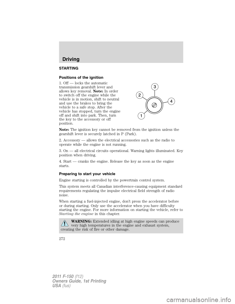
Positions of the ignition
1. Off — locks the automatic
transmission gearshift lever and
allows key removal.Note:In order
to switch off the engine while the
vehicle is in motion, shift to neutral
and use the brakes to bring the
vehicle to a safe stop. After the
vehicle has stopped, turn the engine
off and shift into park. Then, turn
the key to the accessory or off
position.
Note:The ignition key cannot be removed from the ignition unless the
gearshift lever is securely latched in P (Park).
2. Accessory — allows the electrical accessories such as the radio to
operate while the engine is not running.
3. On — all electrical circuits operational. Warning lights illuminated. Key
position when driving.
4. Start — cranks the engine. Release the key as soon as the engine
starts.
Preparing to start your vehicle
Engine starting is controlled by the powertrain control system.
This system meets all Canadian interference-causing equipment standard
requirements regulating the impulse electrical field strength of radio
noise.
When starting a fuel-injected engine, don’t press the accelerator before
or during starting. Only use the accelerator when you have difficulty
starting the engine. For more information on starting the vehicle, refer to
Starting the enginein this chapter.
WARNING:Extended idling at high engine speeds can produce
very high temperatures in the engine and exhaust system,
creating the risk of fire or other damage.
Driving
272
2011 F-150(f12)
Owners Guide, 1st Printing
USA(fus)
Page 276 of 461

If you should experience cold weather starting problems on E85ethanol,
and neither an alternative brand of E
85ethanol nor an engine block
heater is available, the addition of unleaded gasoline to your tank will
improve cold starting performance. Your vehicle is designed to operate
on E
85ethanol alone, unleaded gasoline alone, or any mixture of the two.
SeeChoosing the right fuelin theMaintenance and Specifications
chapter for more information on ethanol.
If the engine fails to start using the preceding instructions
(flexible fuel vehicles only)
1. Press and hold down the accelerator 1/3 to 1/2 way to floor, then
crank the engine.
2. When the engine starts, release the key, then gradually release the
accelerator pedal as the engine speeds up. If the engine still fails to start,
repeat Step 1.
Guarding against exhaust fumes
Carbon monoxide is present in exhaust fumes. Take precautions to avoid
its dangerous effects.
WARNING:If you smell exhaust fumes inside your vehicle, have
your dealer inspect your vehicle immediately. Do not drive if you
smell exhaust fumes.
Important ventilating information
If the engine is idling while the vehicle is stopped for a long period of
time, open the windows at least 1 inch (2.5 cm) or adjust the heating or
air conditioning to bring in fresh air.
ENGINE BLOCK HEATER (IF EQUIPPED)
An engine block heater warms the engine coolant which aids in starting
and allows the heater/defroster system to respond quickly. If your vehicle
is equipped with this system, your equipment includes a heater element
which is installed in your engine block and a wire harness which allows
the user to connect the system to a grounded 120 volt A/C electrical
source. The block heater system is most effective when outdoor
temperatures reach below 0°F (-18°C).
For flexible fuel vehicles, if operating with E
85ethanol, an engine block
heater must be used if ambient temperature is below 0°F (-18°C).
SeeCold weather startingearlier in this chapter for more information
on starting with ethanol.
Driving
276
2011 F-150(f12)
Owners Guide, 1st Printing
USA(fus)
Page 277 of 461

WARNING:Failure to follow engine block heater instructions
could result in property damage or physical injury.
WARNING:To reduce the risk of electrical shock, do not use
your heater with ungrounded electrical systems or two-pronged
(cheater) adapters.
Prior to using the engine block heater, follow these recommendations for
proper and safe operation:
•For your safety, use an outdoor extension cord that is product
certified by Underwriter’s Laboratory (UL) or Canadian Standards
Association (CSA). Use only an extension cord that can be used
outdoors, in cold temperatures, and is clearly marked “Suitable for Use
with Outdoor Appliances.” Never use an indoor extension cord
outdoors; it could result in an electric shock or fire hazard.
•Use a 16 gauge outdoor extension cord, minimum.
•Use as short an extension cord as possible.
•Do not use multiple extension cords. Instead, use one extension cord
which is long enough to reach from the engine block heater cord to
the outlet without stretching.
•Make certain that the extension cord is in excellent condition (not
patched or spliced). Store your extension cord indoors at
temperatures above 32°F (0°C). Outdoor conditions can deteriorate
extension cords over a period of time.
•To reduce the risk of electrical shock, do not use your heater with
ungrounded electrical systems or two pronged (cheater) adapters.
Also ensure that the block heater, especially the cord, is in good
condition before use.
•Make sure that when in operation, the extension cord plug /engine
block heater cord plug connection is free and clear of water in order
to prevent possible shock or fire.
•Be sure that areas where the vehicle is parked are clean and clear of
all combustibles such as petroleum products, dust, rags, paper and
similar items.
•Be sure that the engine block heater, heater cord and extension cord
are solidly connected. A poor connection can cause the cord to
become very hot and may result in an electrical shock or fire. Be sure
to check for heat anywhere in the electrical hookup once the system
has been operating for approximately a half hour.
Driving
277
2011 F-150(f12)
Owners Guide, 1st Printing
USA(fus)