2011 FORD F150 set clock
[x] Cancel search: set clockPage 49 of 461

7.CLK (Clock):Press CLK to
toggle between displaying the radio
frequency and the clock setting.
Setting the clock:Press and hold
CLK until the hours begin to flash. Press
//SEEKto
manually increase/decrease the hours.
Press CLK again to set the minutes using
//SEEKto
manually increase/decrease the minutes. Allow 10 seconds to pass to
confirm that the time has been set.
AM/FM in-dash CD/MP3 satellite compatible sound system
WARNING:Driving while distracted can result in loss of vehicle
control, accident and injury. Ford strongly recommends that
drivers use extreme caution when using any device or feature that may
take their focus off the road. Your primary responsibility is the safe
operation of the vehicle. We recommend against the use of any
handheld device while driving, encourage the use of voice-operated
systems when possible and that you become aware of applicable state
and local laws that may affect use of electronic devices while driving.
OKTUNE LOAD
VOLCD
AUX AM/FM
SIRIUS TEXT
SCANCAT/FOLDCLOCK #
SOUNDMENU
SEEK
1
23
45
6
78
90
Entertainment Systems
49
2011 F-150(f12)
Owners Guide, 1st Printing
USA(fus)
Page 50 of 461

Accessory delay:Your vehicle is equipped with accessory delay. With
this feature, the radio and other electrical accessories may be used for
up to ten minutes after the ignition is turned off or until either front
door is opened.
Battery management:When the engine is off, your audio system may
turn off if the battery is at a low state of charge or if the ignition has
been in the accessory position or in the on position for approximately
45 minutes. The display will temporarily show SYS OFF TO SAVE BATT
and the audio system will be turned off. The audio system will return to
normal operation once the vehicle has been started and battery state of
charge allowed to recover. The battery state of charge recovery can be
accelerated by turning off any unnecessary electrical loads while driving.
Note:Your vehicle is equipped with
a unique audio system. If your
display shows six small circles in the
display, your audio system is a CD6
system (six disc changer). If not,
your system is a single CD system.
Setting the clock
To set the time, press CLOCK. The display will read SET TIME. Use the
memory preset numbers (0–9) to enter in the desired time–hours and
minutes and press OK. The clock will then begin from that time.
AM/FM Radio
/ VOL (Power/Volume):Press
to turn the radio on/off. Turn the
knob to increase/decrease volume.
If the volume is set above a certain
level and the ignition is turned off,
the volume will come back on at a
nominal listening level when the ignition switch is turned back on.
AM/FM:Press repeatedly to select AM/FM1/FM2 frequency band.
TUNE:Turn the knob to go
up/down the frequency band in
individual increments.
DIRECT:Press DIRECT and then manually enter the desired radio
station (i.e. 93.9) using the memory preset numbers (0–9).
Entertainment Systems
50
2011 F-150(f12)
Owners Guide, 1st Printing
USA(fus)
Page 104 of 461

EXTERIOR MIRRORS
Power side view mirrors (if equipped)
WARNING:Do not adjust the mirror while the vehicle is in
motion.
To adjust your mirrors:
1. Rotate the control clockwise to
adjust the right mirror and rotate
the control counterclockwise to
adjust the left mirror.
2. Move the control in the direction
you wish to tilt the mirror.
3. Return to the center position to lock mirrors in place.
Memory feature (if equipped)
The power side view mirror positions are saved when doing a memory
set function and can be recalled along with the vehicle personality
features when a memory position is selected through the remote entry
transmitter, keyless entry keypad or memory switch on the driver’s seat.
Refer toMemory seats and mirrorsin theSeating and Safety
Restraintschapter.
Automatic dimming feature (if equipped)
The driver’s side view mirror has an auto-dimming function. For more
information, refer toAutomatic dimming interior rear view mirrorin
this chapter.
Driver Controls
104
2011 F-150(f12)
Owners Guide, 1st Printing
USA(fus)
Page 249 of 461

3. Cycle the ignition to the on
position with the engine off.
4. Turn the hazard flashers on then
off three times. This must be
accomplished within 10 seconds.
If the reset mode has been entered successfully, the horn will sound
once, the TPMS indicator
will flash and the message center (if
equipped) will displayTRAIN LEFT FRONT TIRE. If this does not
occur, please try again starting at Step 2.
If after repeated attempts to enter the reset mode, the horn does not
sound, the TPMS indicator
does not flash and the message center (if
equipped) does not displayTRAIN LEFT FRONT TIRE, seek service
from your authorized dealer.
5. Train the TPMS sensors in the tires using the following TPMS reset
sequence starting with theleft front tirein the following clockwise
order:
•Left front (Driver’s side front tire)
•Right front (Passenger’s side front tire)
•Right rear (Passenger’s side rear tire)
•Left rear (Driver’s side rear tire)
6. Remove the valve cap from the valve stem on the left front tire;
decrease the air pressure until the horn sounds.
Note:The single horn chirp confirms that the sensor identification code
has been learned by the module for this position. If a double horn is
heard, the reset procedure was unsuccessful, and must be repeated.
7. Remove the valve cap from the valve stem on the right front tire;
decrease the air pressure until the horn sounds.
Tires, Wheels and Loading
249
2011 F-150(f12)
Owners Guide, 1st Printing
USA(fus)
Page 335 of 461

•Load leveling adjustment (if applicable)
When driving with the full-size dissimilar spare tire/wheel additional
caution should be given to:
•Towing a trailer
•Driving vehicles equipped with a camper body
•Driving vehicles with a load on the cargo rack
Drive cautiously when using a full-size dissimilar spare tire/wheel and
seek service as soon as possible.
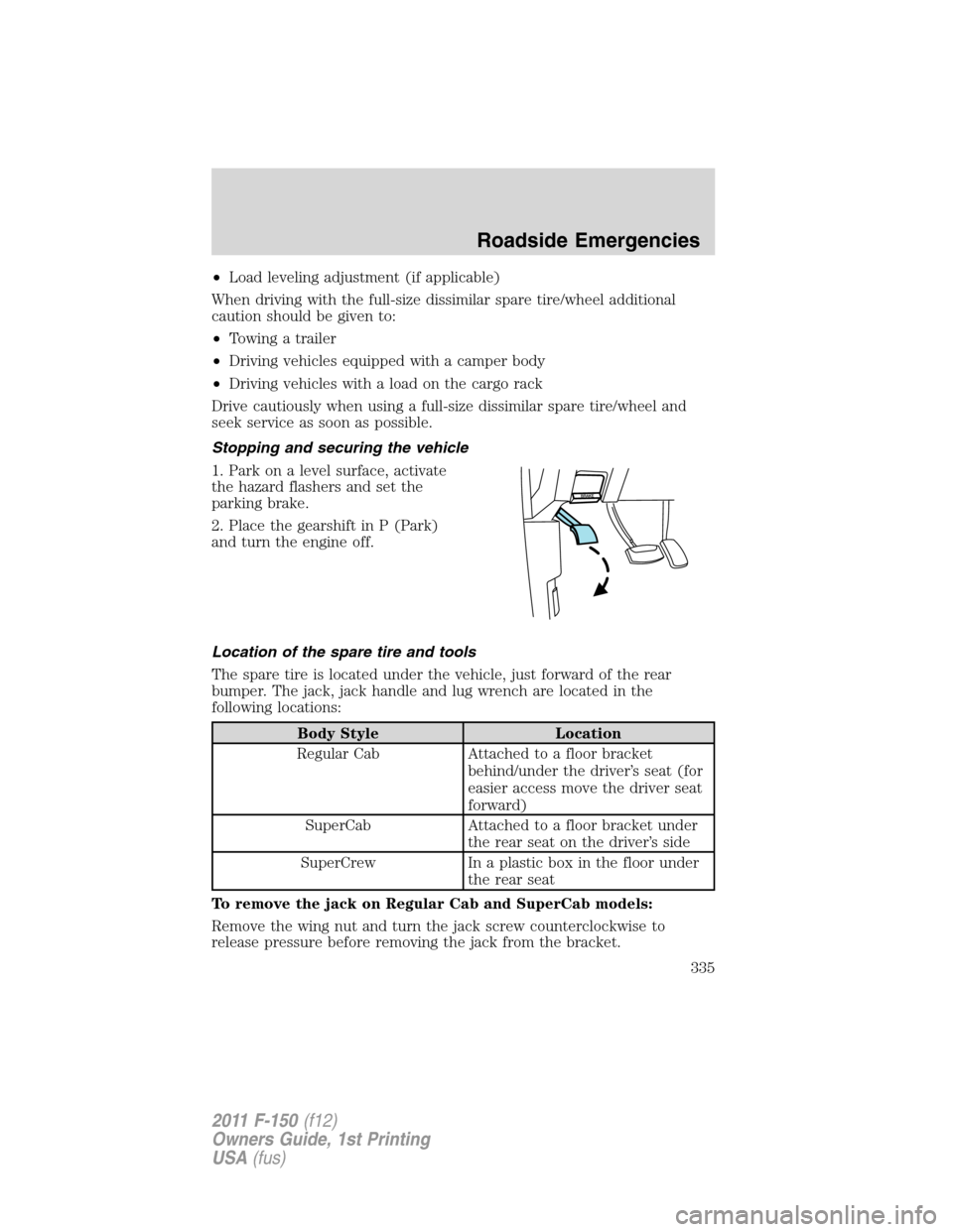
Stopping and securing the vehicle
1. Park on a level surface, activate
the hazard flashers and set the
parking brake.
2. Place the gearshift in P (Park)
and turn the engine off.
Location of the spare tire and tools
The spare tire is located under the vehicle, just forward of the rear
bumper. The jack, jack handle and lug wrench are located in the
following locations:
Body Style Location
Regular Cab Attached to a floor bracket
behind/under the driver’s seat (for
easier access move the driver seat
forward)
SuperCab Attached to a floor bracket under
the rear seat on the driver’s side
SuperCrew In a plastic box in the floor under
the rear seat
To remove the jack on Regular Cab and SuperCab models:
Remove the wing nut and turn the jack screw counterclockwise to
release pressure before removing the jack from the bracket.
Roadside Emergencies
335
2011 F-150(f12)
Owners Guide, 1st Printing
USA(fus)
Page 336 of 461

To remove the jack on SuperCrew models:
1. Lift both rear seat cushions.
2. Remove the insert containing the Easy Fuel ™ funnel from the driver’s
side.
3. Remove the two small wing nuts on the passenger side.
4. Slide the plastic box toward the driver’s side and remove.
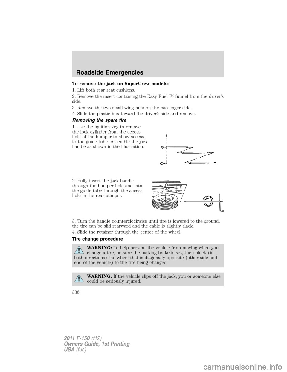
Removing the spare tire
1. Use the ignition key to remove
the lock cylinder from the access
hole of the bumper to allow access
to the guide tube. Assemble the jack
handle as shown in the illustration.
2. Fully insert the jack handle
through the bumper hole and into
the guide tube through the access
hole in the rear bumper.
3. Turn the handle counterclockwise until tire is lowered to the ground,
the tire can be slid rearward and the cable is slightly slack.
4. Slide the retainer through the center of the wheel.
Tire change procedure
WARNING:To help prevent the vehicle from moving when you
change a tire, be sure the parking brake is set, then block (in
both directions) the wheel that is diagonally opposite (other side and
end of the vehicle) to the tire being changed.
WARNING:If the vehicle slips off the jack, you or someone else
could be seriously injured.
Roadside Emergencies
336
2011 F-150(f12)
Owners Guide, 1st Printing
USA(fus)
Page 337 of 461

WARNING:Do not attempt to change a tire on the side of the
vehicle close to moving traffic. Pull far enough off the road to
avoid the danger of being hit when operating the jack or changing the
wheel.
Note:Passengers should not remain in the vehicle when the vehicle is
being jacked.
Refer to the instruction sheet (located with the jack) for detailed tire
change instructions.
1. Block the diagonally opposite
wheel.
2. Obtain the spare tire and jack
from their storage locations.Note:
F-150 SVT Raptor also includes a
chock, saddle extension and wing
bolt.
3. Use the tip of the lug wrench to remove any wheel trim that is
blocking the lug nuts.
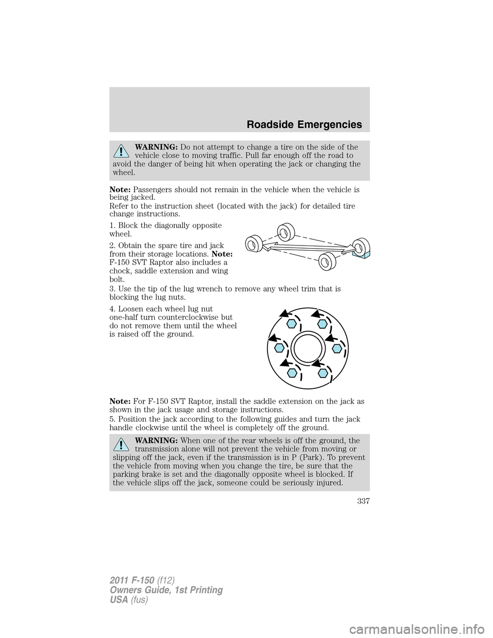
4. Loosen each wheel lug nut
one-half turn counterclockwise but
do not remove them until the wheel
is raised off the ground.
Note:For F-150 SVT Raptor, install the saddle extension on the jack as
shown in the jack usage and storage instructions.
5. Position the jack according to the following guides and turn the jack
handle clockwise until the wheel is completely off the ground.
WARNING:When one of the rear wheels is off the ground, the
transmission alone will not prevent the vehicle from moving or
slipping off the jack, even if the transmission is in P (Park). To prevent
the vehicle from moving when you change the tire, be sure that the
parking brake is set and the diagonally opposite wheel is blocked. If
the vehicle slips off the jack, someone could be seriously injured.
Roadside Emergencies
337
2011 F-150(f12)
Owners Guide, 1st Printing
USA(fus)
Page 380 of 461

If the battery has been disconnected or a new battery has been installed,
the clock and radio settings must be reset once the battery is
reconnected.
•Always dispose of automotive
batteries in a responsible manner.
Follow your local authorized
standards for disposal. Call your
local authorized recycling center
to find out more about recycling
automotive batteries.
Battery management system (if equipped)
The battery management system (BMS) monitors battery conditions and
takes actions to extend battery life. If excessive battery drain is
detected, the system may temporarily disable certain electrical features
to protect the battery. Those electrical accessories effected include rear
defrost, heated /cooled seats, climate control fan, heated steering wheel
and audio system. A message may be displayed on the instrument cluster
or center stack display to alert the driver that battery protections actions
are active. See theMessage centerin theInstrument Clustersection
andEntertainment Systemsfor more information. These messages are
only for notification that an action is taking place, and not intended to
indicate an electrical problem or that the battery requires replacement.
Electrical accessory installation
To ensure proper operation of the BMS, any electrical devices that are
added to the vehicle should not have their ground connection made
directly at the negative battery post. A connection at the negative
battery post can cause inaccurate measurements of the battery condition
and potential incorrect system operation.
Note:Electrical or electronic accessories added to the vehicle may
adversely affect battery performance and durability and may also affect
the performance of other electrical systems in the vehicle.
When a battery replacement is required, the battery should only be
replaced with a Ford recommended replacement battery which matches
the electrical requirements of the vehicle.
L
E
A
D
RETURN
RECYCLE
Maintenance and Specifications
380
2011 F-150(f12)
Owners Guide, 1st Printing
USA(fus)