Page 305 of 382
Black plate (63,1)Chevrolet Malibu Owner Manual - 2011
Vehicle Care 10-63
Using the Tire Sealant and
Compressor Kit to Temporarily
Seal and Inflate a
Punctured Tire
Follow the directions closely for
correct sealant usage.
When using the tire sealant and
compressor kit during cold
temperatures, warm the kit in a
heated environment for five minutes.
This will help to inflate the tire
faster.If a tire goes flat, avoid further tire
and wheel damage by driving slowly
to a level place. Turn on the hazard
warning flashers. See
Hazard
Warning Flashers
on page 6‑4.
See If a Tire Goes Flat
on
page 10‑59for other important
safety warnings.
Do not remove any objects that
have penetrated the tire.
1. Remove the tire sealant and compressor kit from its storage
location. See Storing the Tire
Sealant and Compressor Kit
on
page 10‑68.
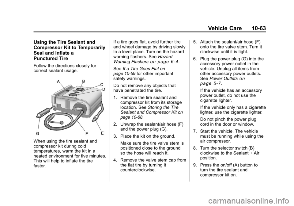
2. Unwrap the sealant/air hose (F) and the power plug (G).
3. Place the kit on the ground. Make sure the tire valve stem is
positioned close to the ground
so the hose will reach it.
4. Remove the valve stem cap from the flat tire by turning it
counterclockwise. 5. Attach the sealant/air hose (F)
onto the tire valve stem. Turn it
clockwise until it is tight.
6. Plug the power plug (G) into the accessory power outlet in the
vehicle. Unplug all items from
other accessory power outlets.
See Power Outlets
on
page 5‑7.
If the vehicle has an accessory
power outlet, do not use the
cigarette lighter.
If the vehicle only has a cigarette
lighter, use the cigarette lighter.
Do not pinch the power plug
cord in the door or window.
7. Start the vehicle. The vehicle must be running while using the
air compressor.
8. Turn the selector switch (B) clockwise to the Sealant + Air
position.
9. Press the on/off (A) button to turn the tire sealant and
compressor kit on.
Page 306 of 382
Black plate (64,1)Chevrolet Malibu Owner Manual - 2011
10-64 Vehicle Care
The compressor will inject
sealant and air into the tire.
The pressure gauge (D) will
initially show a high pressure
while the compressor pushes the
sealant into the tire. Once the
sealant is completely dispersed
into the tire, the pressure will
quickly drop and start to rise
again as the tire inflates with
air only.
10. Inflate the tire to the recommended inflation
pressure using the pressure
gauge (D). The recommended
inflation pressure can be found
on the Tire and Loading
Information label. See Tire
Pressure on page 10‑45.
The pressure gauge (D) may
read higher than the actual tire
pressure while the compressor
is on. Turn the compressor off
to get an accurate pressure
reading. The compressor may
be turned on/off until the
correct pressure is reached. Notice:
If the recommended
pressure cannot be reached after
approximately 25 minutes, the
vehicle should not be driven
farther. The tire is too severely
damaged and the tire sealant and
compressor kit cannot inflate the
tire. Remove the power plug from
the accessory power outlet and
unscrew the inflating hose from
the tire valve. See Roadside
Assistance Program (United
States and Canada)
on page 13‑7or Roadside Assistance Program
(Mexico) on page 13‑9.
11. Press the on/off button (A) to turn the tire sealant and
compressor kit off.
The tire is not sealed and will
continue to leak air until the
vehicle is driven and the
sealant is distributed in the tire;
therefore, Steps 12 through
18 must be done immediately
after Step 11. Be careful while handling the
tire sealant and compressor kit
as it could be warm after
usage.
12. Unplug the power plug (G) from the accessory power outlet in
the vehicle.
13. Turn the sealant/air hose (F) counterclockwise to remove it
from the tire valve stem.
14. Replace the tire valve stem cap.
15. Return the sealant/air hose (F) and the power plug (G) back in
their original locations.
Page 308 of 382
Black plate (66,1)Chevrolet Malibu Owner Manual - 2011
10-66 Vehicle Care
Using the Tire Sealant and
Compressor Kit without
Sealant to Inflate a Tire
(Not Punctured)
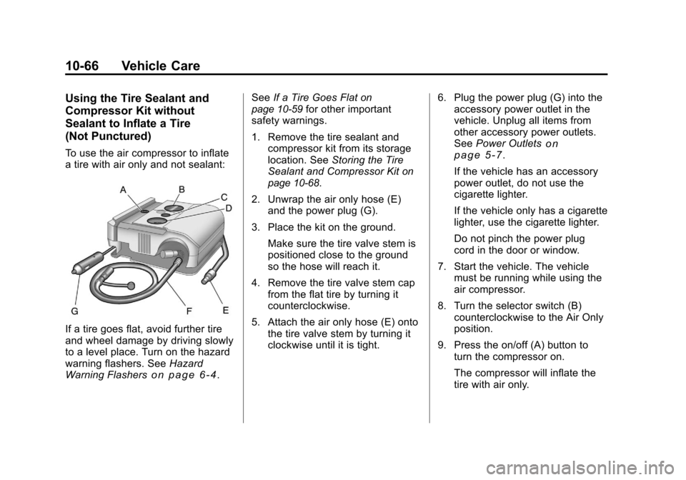
To use the air compressor to inflate
a tire with air only and not sealant:
If a tire goes flat, avoid further tire
and wheel damage by driving slowly
to a level place. Turn on the hazard
warning flashers. SeeHazard
Warning Flashers
on page 6‑4. See
If a Tire Goes Flat
on
page 10‑59for other important
safety warnings.
1. Remove the tire sealant and compressor kit from its storage
location. See Storing the Tire
Sealant and Compressor Kit
on
page 10‑68.
2. Unwrap the air only hose (E) and the power plug (G).
3. Place the kit on the ground. Make sure the tire valve stem is
positioned close to the ground
so the hose will reach it.
4. Remove the tire valve stem cap from the flat tire by turning it
counterclockwise.
5. Attach the air only hose (E) onto the tire valve stem by turning it
clockwise until it is tight. 6. Plug the power plug (G) into the
accessory power outlet in the
vehicle. Unplug all items from
other accessory power outlets.
See Power Outlets
on
page 5‑7.
If the vehicle has an accessory
power outlet, do not use the
cigarette lighter.
If the vehicle only has a cigarette
lighter, use the cigarette lighter.
Do not pinch the power plug
cord in the door or window.
7. Start the vehicle. The vehicle must be running while using the
air compressor.
8. Turn the selector switch (B) counterclockwise to the Air Only
position.
9. Press the on/off (A) button to turn the compressor on.
The compressor will inflate the
tire with air only.
Page 309 of 382
Black plate (67,1)Chevrolet Malibu Owner Manual - 2011
Vehicle Care 10-67
10. Inflate the tire to therecommended inflation
pressure using the pressure
gauge (D). The recommended
inflation pressure can be found
on the Tire and Loading
Information label. See Tire
Pressure on page 10‑45.
The pressure gauge (D) may
read higher than the actual tire
pressure while the compressor
is on. Turn the compressor off
to get an accurate reading. The
compressor may be turned on/
off until the correct pressure is
reached. If the tire is inflated
higher than the recommended
pressure, press the pressure
relief button (C), if equipped,
until the proper pressure
reading is reached. This option
is only functional when using
the air only hose (E). 11. Press the on/off button (A) to
turn the tire sealant and
compressor kit off.
Be careful while handling the
tire sealant and compressor kit
as it could be warm after
usage.
12. Unplug the power plug (G) from the accessory power outlet in
the vehicle.
13. Disconnect the air only hose (E) from the tire valve
stem, by turning it
counterclockwise, and replace
the tire valve stem cap.
14. Return the air only hose (E) and the power plug (G) back to
their original locations.
15. Return the equipment to its original storage location in the
vehicle.Removal and Installation of the
Sealant Canister
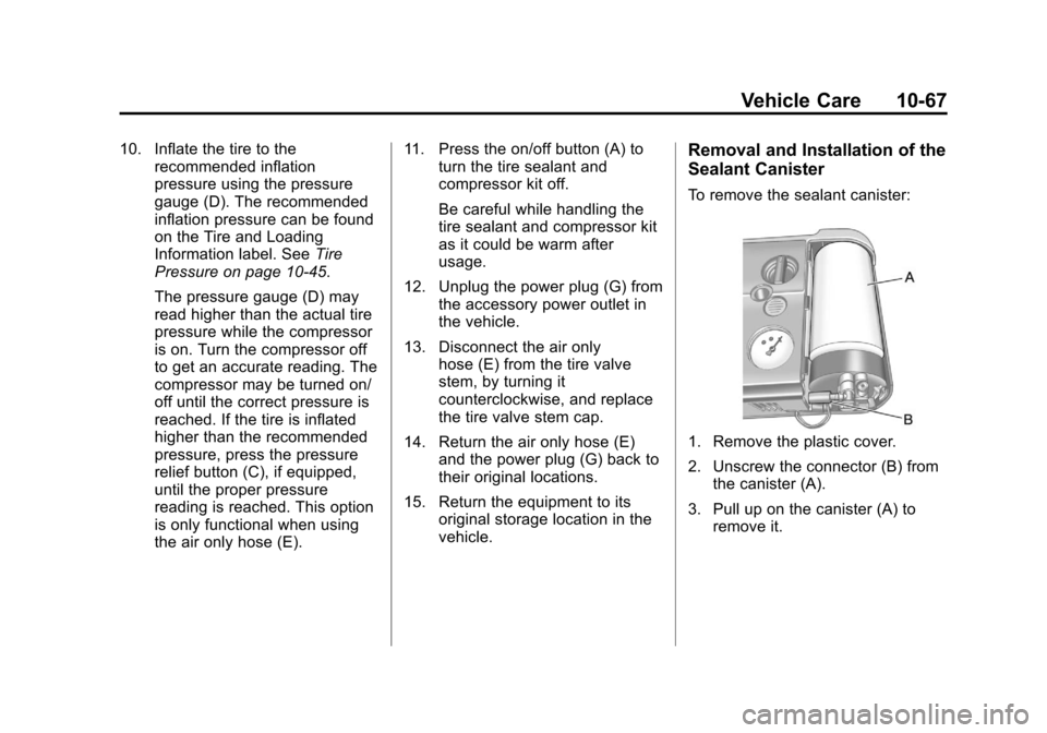
To remove the sealant canister:
1. Remove the plastic cover.
2. Unscrew the connector (B) from
the canister (A).
3. Pull up on the canister (A) to remove it.
Page 310 of 382
Black plate (68,1)Chevrolet Malibu Owner Manual - 2011
10-68 Vehicle Care
4. Replace with a new canisterwhich is available from your
dealer.
5. Push the new canister into place.
6. Screw the connector (B) to the canister (A).
7. Slide the plastic cover back on.
Storing the Tire Sealant
and Compressor Kit
The tire sealant and compressor kit
is located in the trunk.
1. Open the trunk. See Trunk
on
page 2‑10.
2. Lift the cover.
3. Turn the retainer clockwise and remove the tire sealant and
compressor kit.
To store the tire sealant and
compressor kit, reverse the steps.
Tire Changing
Removing the Spare Tire and
Tools
The equipment you will need is in
the trunk.
1. Open the trunk. See Trunk
on
page 2‑10for more information.
2. Remove the spare tire cover.
Page 311 of 382
Black plate (69,1)Chevrolet Malibu Owner Manual - 2011
Vehicle Care 10-69
3. Turn the wing nutcounterclockwise and remove it.
Then remove the compact spare
tire. See Compact Spare Tire
on
page 10‑77for more information.
4. Remove the wing nut holding the jack in place.
5. Remove the jack and wheel wrench from the trunk.
Tire Changing Tools
The tools you will be using include
the wheel wrench (A) and jack (B).
1. Turn the wing nutcounterclockwise to loosen
wheel wrench.
2. Unhook the wheel wrench from the jack.
Page 313 of 382
Black plate (71,1)Chevrolet Malibu Owner Manual - 2011
Vehicle Care 10-71
5. Position the lift head at the jacklocation nearest the flat tire.
Make sure all of the jack lift
head is touching the jacking
flange under the body. Do not
place the jack under a body
panel.
6. Put the compact spare tire near the flat tire.
{WARNING
Getting under a vehicle when it is
jacked up is dangerous. If the
vehicle slips off the jack, you
could be badly injured or killed.
Never get under a vehicle when it
is supported only by a jack.
{WARNING
Raising your vehicle with the jack
improperly positioned can
damage the vehicle and even
make the vehicle fall. To help
avoid personal injury and vehicle
damage, be sure to fit the jack lift
head into the proper location
before raising the vehicle.
7. Raise the vehicle by turning thewrench clockwise. Raise the
vehicle far enough off the
ground so there is enough room
for the compact spare tire to fit.
Page 315 of 382
Black plate (73,1)Chevrolet Malibu Owner Manual - 2011
Vehicle Care 10-73
{WARNING
Never use oil or grease on bolts
or nuts because the nuts might
come loose. The vehicle's wheel
could fall off, causing a crash.
12. Put the wheel nuts back on with the rounded end toward
the wheel. Tighten each nut by
hand or with the wrench until
the wheel is held against
the hub.
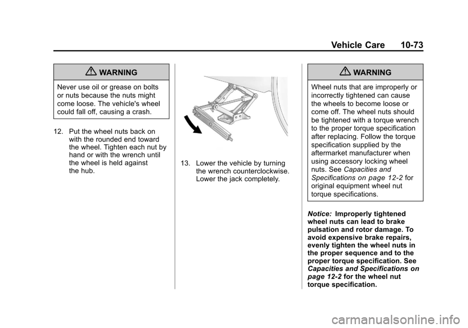
13. Lower the vehicle by turningthe wrench counterclockwise.
Lower the jack completely.
{WARNING
Wheel nuts that are improperly or
incorrectly tightened can cause
the wheels to become loose or
come off. The wheel nuts should
be tightened with a torque wrench
to the proper torque specification
after replacing. Follow the torque
specification supplied by the
aftermarket manufacturer when
using accessory locking wheel
nuts. See Capacities and
Specifications
on page 12‑2for
original equipment wheel nut
torque specifications.
Notice: Improperly tightened
wheel nuts can lead to brake
pulsation and rotor damage. To
avoid expensive brake repairs,
evenly tighten the wheel nuts in
the proper sequence and to the
proper torque specification. See
Capacities and Specifications
on
page 12‑2for the wheel nut
torque specification.