2011 BMW 535I rear entertainment
[x] Cancel search: rear entertainmentPage 5 of 304

Contents
The fastest way to find information on a partic‐
ular topic or item is by using the index, refer to
page
294.
Using this Owner's Manual
6 Notes
At a glance
12 Cockpit
16 iDrive
22 Voice activation system
24 Integrated Owner's Manual in the vehicle
Controls
28 Opening and closing
44 Adjusting
54 Transporting children safely
58 Driving
67 Displays
80 Lamps
85 Safety
95 Driving stability control systems
102 Driving comfort
126 Climate control
132 Interior equipment
138 Storage compartments
Driving tips
146 Things to remember when driving
Navigation
154 Navigation
Entertainment
172 Tone
174 Radio
181 CD/multimedia
201 Rear entertainment Communication
210
Telephone
221 Office
230 Contacts
232 BMW ConnectedDrive
Mobility
240 Refueling
241 Fuel
242 Wheels and tires
255 Engine compartment
257 Engine oil
260 Maintenance
262 Replacing components
269 Breakdown assistance
274 Care
Reference
280 Technical data
285 Short commands of the voice activation
system
294 Everything from A to Z
Seite 5
Online Edition for Part no. 01 40 2 606 469 - 03 11 490 Reference Mobility Communication Entertainment Navigation Driving tips Controls At a glance
Page 19 of 304

4.
Turn the controller until "Time/Date" is high‐
lighted, and then press the controller. 5.
Turn the controller until "Time:" is high‐
lighted, and then press the controller. 6.
Turn the controller to set the hours and
press the controller.
7. Turn the controller to set the minutes and
press the controller.
Status information
Status field
The
following information is displayed in the sta‐
tus field at the top right:
▷ Time.
▷ Current entertainment source.
▷ Sound output, on/off.
▷ Wireless network reception strength.
▷ Telephone status.
▷ Traffic bulletin reception*.
Status field symbols
The symbols are grouped as follows. Radio symbols Symbol Meaning
Traffic bulletins* are switched on.
HD Radio™* is switched on.
Satellite radio* is switched on.
Telephone symbols
Symbol Meaning
Incoming or outgoing call*.
Missed call*.
Wireless network reception
strength*
Symbol flashes: searching
for network. Wireless network is not available*.
Bluetooth* is switched on.
Roaming* is active.
Text message* was received.
Check the SIM card*.
SIM card* is blocked.
SIM card* is missing.
Enter the PIN*.
Entertainment symbols
Symbol Meaning
CD/DVD* player.
Music collection*.
Gracenote® database*.
AUX-IN port.
Rear AUX-IN port on the left*.
Rear AUX-IN port on the right*. Seite 19
19Online Edition for Part no. 01 40 2 606 469 - 03 11 490
Reference Mobility Communication Entertainment Navigation Driving tips Controls
At a glance
Page 39 of 304

If this occurs, open or close the vehicle using the
buttons
on the remote control or use a key in the
door lock.
To subsequently start the engine, hold the re‐
mote control against the marked area on the
steering column, refer to page 29.
Alarm system*
The concept
The vehicle alarm system responds to:
▷ Opening of a door, the hood or the trunk lid.
▷ Movements in the vehicle: interior motion
sensor, refer to page 40.
▷ Changes in the vehicle tilt, e.g., during at‐
tempts to steal a wheel or when towing the
car.
▷ Interruptions in battery voltage.
The alarm system briefly indicates tampering:
▷ By sounding an acoustic alarm.
▷ By switching on the hazard warning system.
▷ By flashing the high beams.
Arming and disarming the alarm
system
General information
When
you lock or unlock the vehicle, either with
the remote control or at the door lock*, the alarm
system is armed or disarmed at the same time.
Door lock and armed alarm system
Unlocking via the door lock will trigger the alarm
on some country-specific versions.
Trunk lid and armed alarm system
The trunk lid can be opened using the remote
control, even if the alarm system is armed.
Press the button on the remote control
for approx. 1 second and release.
After the trunk lid is closed, it is locked and
monitored again by the alarm system. The haz‐
ard warning system flashes once. In some vehicle equipment variants, the trunk lid
can only be opened using the remote control if
the vehicle was unlocked first.
Panic mode*
Press
the button on the remote control
for at least 3 seconds.
Switching off the alarm
▷ Unlock the vehicle using the remote control.
▷ With Comfort Access: If you are carrying the
remote control with you, pull on the door
handle.
Indicator lamp on the interior rearview
mirror ▷
The indicator lamp flashes briefly every
2 seconds:
The system is armed.
▷ The indicator lamp flashes after locking:
The doors, hood or trunk lid is not closed
properly, but the rest of the vehicle is se‐
cured.
After
10 seconds, the indicator lamp flashes
continuously. The interior motion sensor is
not active.
▷ The indicator lamp goes out after unlocking:
The vehicle has not been tampered with.
▷ The indicator lamp flashes after unlocking
until
the engine is started, but no longer than
approx. 5 minutes:
An alarm has been triggered.
Tilt alarm sensor
The tilt of the vehicle is monitored. Seite 39
39Online Edition for Part no. 01 40 2 606 469 - 03 11 490
Reference Mobility Communication Entertainment Navigation Driving tips
Controls At a glance
Page 41 of 304

Closing without the pinch protection
system
Danger of pinching
Monitor the closing process and make
sure
that the closing path of the window is clear;
otherwise, injuries may result.◀
For example, if there is an external danger or if
ice on the windows prevents a window from
closing normally, proceed as follows:
1. Pull the switch past the resistance point and
hold it there.
Pinch protection is limited and the window
reopens
slightly if the closing force exceeds
a certain value.
2. Pull the switch past the resistance point
again within approx. 4 seconds and hold it
there.
The window closes without pinch protec‐
tion.
Safety switch
The safety switch in the driver's door can be
used to prevent children, for example, from
opening
and closing the rear windows using the
switches in the rear.
Switching on and off
Press the button.
The LED lights up if the safety function
is switched on.
Safety switch for rear operation
Press the safety switch when transporting
children in the rear; otherwise, injury may result
if the windows are closed without supervision.◀
Roller sunblinds*
General information
If you are no longer able to move the roller sun‐
blind for the rear window after having activated
it a number of times in a row, the system is blocked for a limited time to prevent overheat‐
ing. Let the system cool.
The roller sunblind for the rear window cannot
be moved at low interior temperatures.
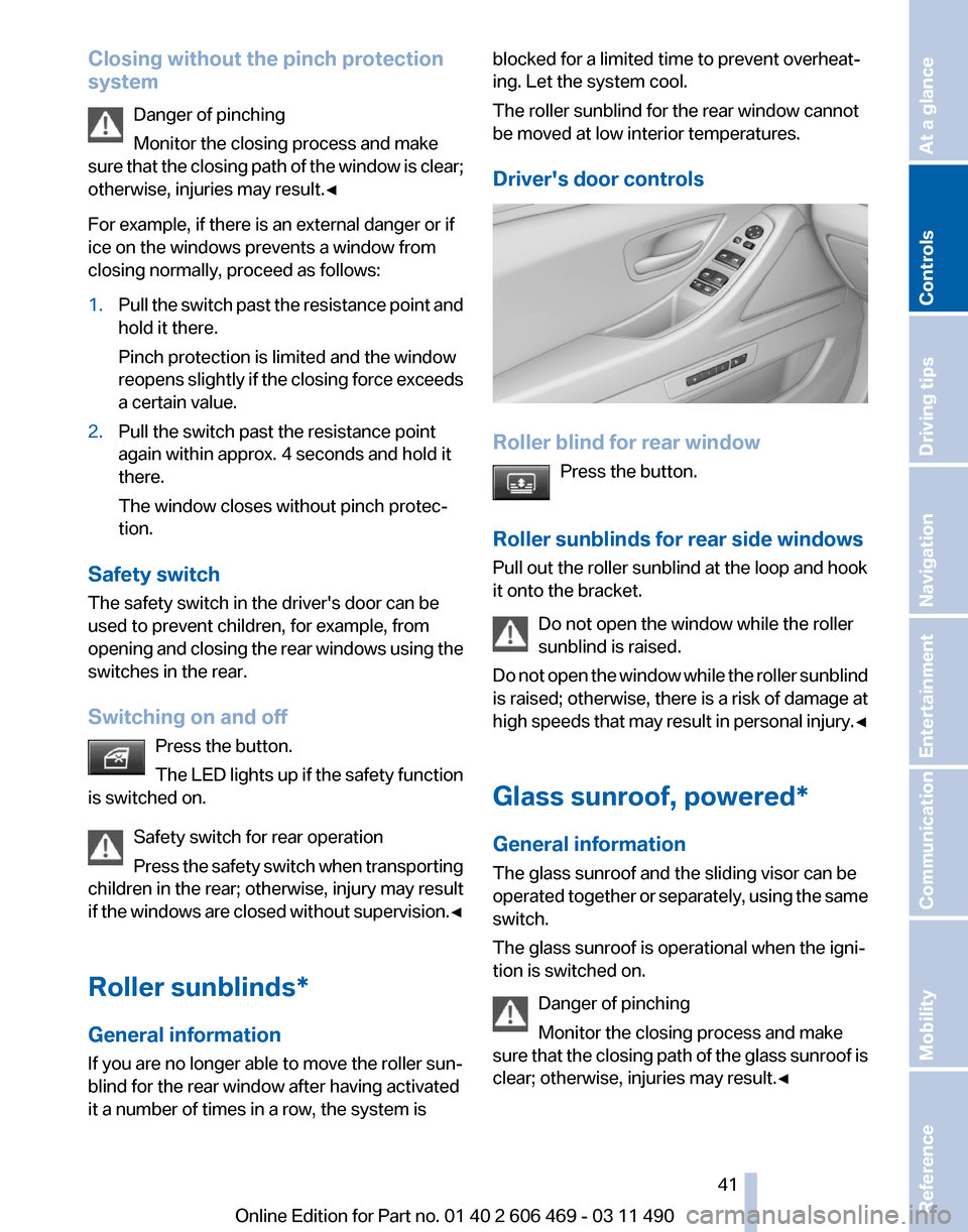
Driver's door controls
Roller blind for rear window
Press the button.
Roller sunblinds for rear side windows
Pull out the roller sunblind at the loop and hook
it onto the bracket. Do not open the window while the roller
sunblind is raised.
Do
not open the window while the roller sunblind
is raised; otherwise, there is a risk of damage at
high speeds that may result in personal injury.◀
Glass sunroof, powered*
General information
The glass sunroof and the sliding visor can be
operated together or separately, using the same
switch.
The glass sunroof is operational when the igni‐
tion is switched on.
Danger of pinching
Monitor the closing process and make
sure that the closing path of the glass sunroof is
clear; otherwise, injuries may result.◀ Seite 41
41Online Edition for Part no. 01 40 2 606 469 - 03 11 490
Reference Mobility Communication Entertainment Navigation Driving tips
Controls At a glance
Page 47 of 304

Front seat heating*
Switching on
Press the button once for each temper‐
ature level.
The maximum temperature is reached when
three LEDs are lit.
Switching off
Press the button longer.
The LEDs go out.
The temperature may be reduced or seat heat‐
ing may be switched off entirely to save battery
power.
Temperature distribution*
The heating action in the seat cushion and back‐
rest can be distributed in different ways.
1. "Climate"
2. "Seat heating distribution"
3. Select the required seat. 4.
Turn the controller to set the temperature
distribution. Rear seat heating*
Switching on
Press the button once for each temper‐
ature level.
The maximum temperature is reached when
three LEDs are lit.
Switching off
Press the button longer.
The LEDs go out.
Front active seat ventilation*
The seat cushion and backrest surfaces are
cooled by means of integrated fans.
The ventilation rapidly cools the seat, e.g., if the
vehicle interior is overheated or for continuous
cooling at high temperatures. Switching on
Press
the button once for each ventila‐
tion level.
The highest level is active when three LEDs are
lit. Seite 47
47Online Edition for Part no. 01 40 2 606 469 - 03 11 490
Reference Mobility Communication Entertainment Navigation Driving tips
Controls At a glance
Page 49 of 304

Checking and replacing safety belts
Have the work performed only by your
service center; otherwise, it cannot be ensured
that this safety feature will function properly.◀
Front head restraints
Correctly adjusted head restraint
A correctly adjusted head restraint reduces the
risk
of injury to cervical vertebrae in the event of
an accident.
Adjusting the head restraint
Correctly adjust the head restraints of all
occupied seats; otherwise, there is an increased
risk of injury in an accident.◀
Height
Adjust the head restraint so that its center is ap‐
proximately at ear level.
Distance
Adjust the distance so that the head restraint is
as close as possible to the back of the head.
Active head restraint
In the event of a rear-end collision with a certain
severity, the active head restraint automatically
reduces the distance from the head.
Reduced protective function
▷Do not use seat or head restraint cov‐
ers.
▷ Do not hang objects, e.g., clothes hangers,
on the head restraints.
▷ Only attach accessories approved by BMW
to the seat or head restraint.
Otherwise, the protective function of the active
head
restraint will be impaired and the personal
safety of the occupants will be endangered.◀ Adjusting the height: manual head
restraints
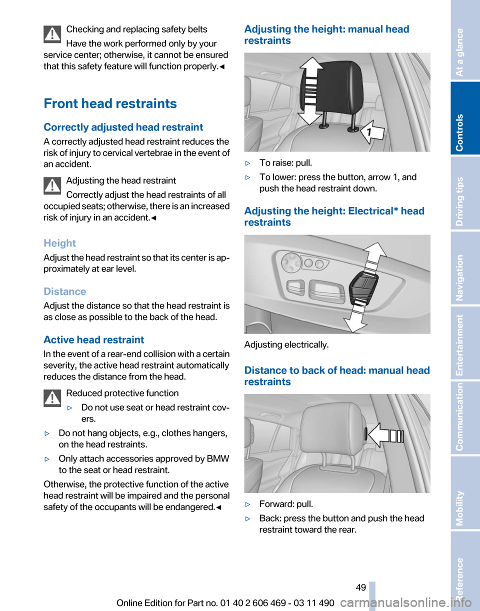
▷
To raise: pull.
▷ To lower: press the button, arrow 1, and
push the head restraint down.
Adjusting the height: Electrical* head
restraints Adjusting electrically.
Distance to back of head: manual head
restraints
▷
Forward: pull.
▷ Back: press the button and push the head
restraint toward the rear.
Seite 49
49Online Edition for Part no. 01 40 2 606 469 - 03 11 490
Reference Mobility Communication Entertainment Navigation Driving tips
Controls At a glance
Page 53 of 304

Interior rearview mirror, automatic
dimming feature
*Photocells are used for control:
▷
In the mirror glass.
▷ On the back of the mirror.
For proper operation:
▷ Keep the photocells clean.
▷ Do not cover the area between the inside
rearview mirror and the windshield.
Steering wheel
General information Do not adjust while driving
Do not adjust the steering wheel while
driving; otherwise, an unexpected movement
could result in an accident.◀
Manual steering wheel adjustment 1.
Fold the lever down.
2. Move the steering wheel to the preferred
height and angle to suit your seating posi‐
tion.
3. Fold the lever back. Power* steering wheel adjustment
The steering wheel can be adjusted in four di‐
rections.
Storing the position
Seat, mirror, and steering wheel memory, refer
to page
51.
Steering wheel heating
*
Switching on/off Press the button.
▷ On: the LED lights up.
▷ Off: the LED goes out. Seite 53
53Online Edition for Part no. 01 40 2 606 469 - 03 11 490
Reference Mobility Communication Entertainment Navigation Driving tips
Controls At a glance
Page 55 of 304

Backrest width*
Before
installing a child restraint fixing system in
the front passenger seat, open the backrest
width completely. Do not change the backrest
width again and do not call up a memory posi‐
tion.
Backrest width for the child seat
Before installing a child restraint fixing
system in the front passenger seat, the backrest
width must be opened completely. Do not
change the adjustment after this; otherwise, the
stability of the child seat will be reduced.◀
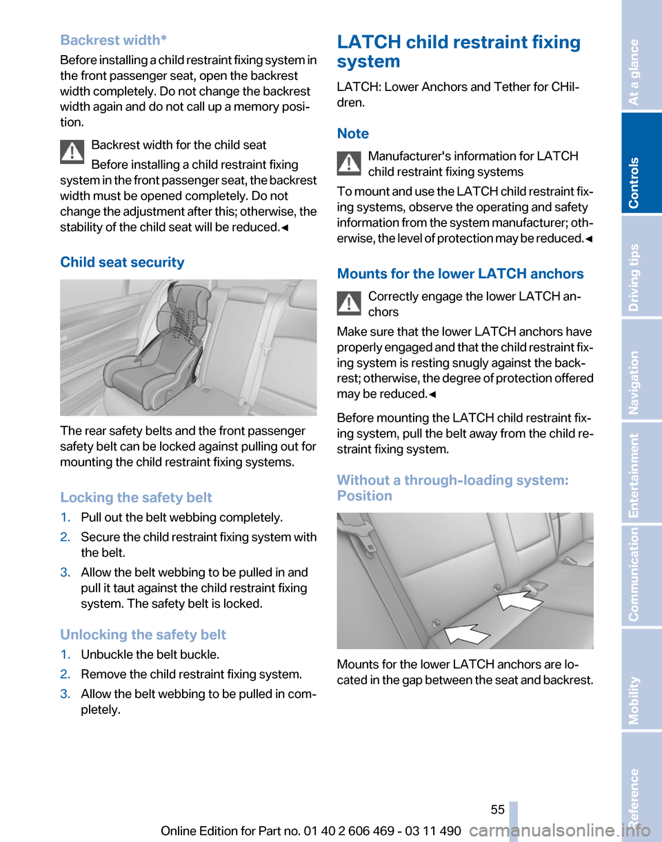
Child seat security The rear safety belts and the front passenger
safety belt can be locked against pulling out for
mounting the child restraint fixing systems.
Locking the safety belt
1.
Pull out the belt webbing completely.
2. Secure the child restraint fixing system with
the belt.
3. Allow the belt webbing to be pulled in and
pull it taut against the child restraint fixing
system. The safety belt is locked.
Unlocking the safety belt
1. Unbuckle the belt buckle.
2. Remove the child restraint fixing system.
3. Allow the belt webbing to be pulled in com‐
pletely. LATCH child restraint fixing
system
LATCH: Lower Anchors and Tether for CHil‐
dren.
Note
Manufacturer's information for LATCH
child restraint fixing systems
To
mount and use the LATCH child restraint fix‐
ing systems, observe the operating and safety
information from the system manufacturer; oth‐
erwise, the level of protection may be reduced.◀
Mounts for the lower LATCH anchors
Correctly engage the lower LATCH an‐
chors
Make sure that the lower LATCH anchors have
properly engaged and that the child restraint fix‐
ing system is resting snugly against the back‐
rest; otherwise, the degree of protection offered
may be reduced.◀
Before mounting the LATCH child restraint fix‐
ing system, pull the belt away from the child re‐
straint fixing system.
Without a through-loading system:
Position Mounts for the lower LATCH anchors are lo‐
cated
in the gap between the seat and backrest. Seite 55
55Online Edition for Part no. 01 40 2 606 469 - 03 11 490
Reference Mobility Communication Entertainment Navigation Driving tips
Controls At a glance