2011 BMW 535I rear entertainment
[x] Cancel search: rear entertainmentPage 111 of 304

Resuming the desired speed
Press the button.
The stored speed is reached and maintained.
Displays in the instrument cluster 1
Display of desired speed
2 Indicator lamp
3 Brief status display
Desired speed
Display in the speedometer: ▷The marking lights up in
green: the system is active.
▷ The marking lights up in or‐
ange: the system has been
interrupted.
▷ The marking does not light up: the system is
switched off.
Brief status display
Brief display in the speedometer: Selected desired speed
If --- appears briefly, conditions may not be ad‐
equate to operate the system.
PDC Park Distance Control*
The concept
In
addition to the PDC Park Distance Control, the
backup camera*, refer to page 113, can be
switched on. PDC supports you when parking. Objects that
you
are approaching slowly in front of or behind
your vehicle are indicated with:
▷ Signal tones.
▷ Visual display.
Measurement
Measurements
are made by ultrasound sensors
in the bumpers.
The range is approx. 6 ft/2 m.
An acoustic warning is first given:
▷ By the front* sensors and the two rear cor‐
ner sensors at approx. 24 in/60 cm.
▷ By the rear middle sensors at approx. 5 ft/
1.50 m.
System limits Check the traffic situation as well
PDC cannot serve as a substitute for the
driver's personal judgment of the traffic situa‐
tion.
Check the traffic situation around the vehi‐
cle with your own eyes. Otherwise, an accident
could result from road users or objects located
outside of the PDC detection range.
Loud noises from outside and inside the vehicle
may prevent you from hearing the PDC's signal
tone.◀
Avoid driving quickly with PDC
Avoid approaching an object quickly.
Avoid driving away quickly while PDC is not yet
active.
For technical reasons, the system may other‐
wise be too late in issuing a warning.◀
Limits of ultrasonic measurement
The detection of objects can reach the physical
limits of ultrasonic measurement, for instance:
▷ With tow bars and trailer hitches.
▷ With thin or wedge-shaped objects.
▷ With low objects.
▷ With objects with corners and sharp edges. Seite 111
111Online Edition for Part no. 01 40 2 606 469 - 03 11 490
Reference Mobility Communication Entertainment Navigation Driving tips
Controls At a glance
Page 113 of 304

If the backup camera image was selected last, it
again
appears on the display. To switch to PDC:
1. "Rear view camera" Select the symbol
on the Control Display.
2. Press the controller.
The setting is stored for the remote control cur‐
rently in use.
Zoom view*
On
the left part of the display screen, the vehicle
is shown enlarged. ▷
Forward gear or transmission position D en‐
gaged: front area of the vehicle.
▷ Reverse gear or transmission position R en‐
gaged: rear area of the vehicle.
Display on the Control Display
Switching
on the backup camera via the
iDrive
With PDC activated: "Rear view camera"
The
backup camera image is displayed. The set‐
ting is stored for the remote control currently in
use.
Malfunction
A Check Control message is displayed. On the Control Display, the areas in front of and
behind the vehicle are shaded. PDC has failed.
Have the system checked.
To ensure full operability:
▷
Keep the sensors clean and free of ice.
▷ When using a pressure washer, keep the
sprayer moving and maintain a distance of
at least 12 in/30 cm from the sensors.
Surround View*
The concept
Surround View includes the following systems:
▷ Backup camera, refer to page 113.
▷ Side View, refer to page 117.
▷ Top View, refer to page 116.
It assists the driver when parking, maneuvering
and on blind driveways and intersections.
Backup camera*
The concept
The
backup camera provides assistance in park‐
ing and maneuvering backwards. The area be‐
hind the vehicle is shown on the Control Display.
System limits
Check the traffic situation as well
Check the traffic situation around the ve‐
hicle with your own eyes. Otherwise, an accident
could result from road users or objects located
outside the picture area of the backup camera.◀ Seite 113
113Online Edition for Part no. 01 40 2 606 469 - 03 11 490
Reference Mobility Communication Entertainment Navigation Driving tips
Controls At a glance
Page 115 of 304

Parking using pathway and turning
circle lines
1.
Position the vehicle so that the turning circle
lines lead to within the limits of the parking
space. 2.
Turn the steering wheel to the point where
the pathway line covers the corresponding
turning circle line. Obstacle marking
▷
Spatially-shaped markings can be shown in
the backup camera image.
Their colored steps match the markings of the
PDC. This simplifies estimation of the distance
to the object shown. Activating the assistance functions
More
than one assistance function can be active
at the same time.
Showing the parking aid lines "Parking aid lines"
Pathway and turning circle lines are displayed.
Showing the obstacle marking "Obstacle marking"
Spatially-shaped markings are displayed.
Display on the Control Display
Switching on the backup camera via
iDrive
With PDC activated: "Rear view camera"
The
backup camera image is displayed. The set‐
ting is stored for the remote control currently in
use.
Brightness
With the backup camera switched on:
1. Select the symbol.
2. Turn the controller until the desired setting
is reached and press the controller.
Contrast
With the backup camera switched on:
1. Select the symbol.
2. Turn the controller until the desired setting
is reached and press the controller.
Seite 115
115Online Edition for Part no. 01 40 2 606 469 - 03 11 490
Reference Mobility Communication Entertainment Navigation Driving tips
Controls At a glance
Page 117 of 304

The display appears as soon as Top View is ac‐
tivated.
If
the backup camera image was selected last, it
again appears on the display. To switch to Top
View: "Rear view camera" Select the symbol on
the Control Display.
The
setting is stored for the remote control cur‐
rently in use.
Display on the Control Display
Switching on the backup camera via
iDrive
With Top View switched on: "Rear view camera"
The
backup camera image is displayed. The set‐
ting is stored for the remote control currently in
use.
Brightness
With Top View switched on:
1. "Brightness"
2. Turn the controller until the desired setting
is reached and press the controller.
Contrast
With Top View switched on:
1. "Contrast"
2. Turn the controller until the desired setting
is reached and press the controller. Displaying the turning circle and
pathway lines
▷
The static, red turning circle line shows the
space needed to the side of the vehicle
when the steering wheel is turned all the
way.
▷ The variable, green pathway line assists you
in assessing the amount of space actually
needed to the side of the vehicle.
The pathway line is dependent on the cur‐
rent steering angle and is continuously ad‐
justed with the steering wheel movement. "Parking aid lines"
Turning circle and pathway lines are displayed.
Cameras The objectives of the Top View cameras are lo‐
cated at the bottom of the exterior mirror hous‐
ings.
The image quality may be impaired by dirt.
Clean the lens, refer to page 276.
Side View*
The concept
Side View provides an early look at cross traffic
at blind driveways and intersections. Road users
concealed by obstacles to the left and right of
the vehicle can only be detected relatively late
from the driver's seat. To improve visibility, two
cameras in the front of the vehicle record the
traffic situation on each side.
System limits
The maximum recording range of the camera is
330 ft/100 m.
Seite 117
117Online Edition for Part no. 01 40 2 606 469 - 03 11 490
Reference Mobility Communication Entertainment Navigation Driving tips
Controls At a glance
Page 129 of 304

Switching on
Press any button.
Microfilter/activated-charcoal filter
The microfilter removes dust and pollen from
the incoming air.
The activated-charcoal filter removes gaseous
pollutants from the outside air that enters the
vehicle.
This combined filter should be replaced during
scheduled
maintenance of your vehicle., refer to
page 260
Ventilation
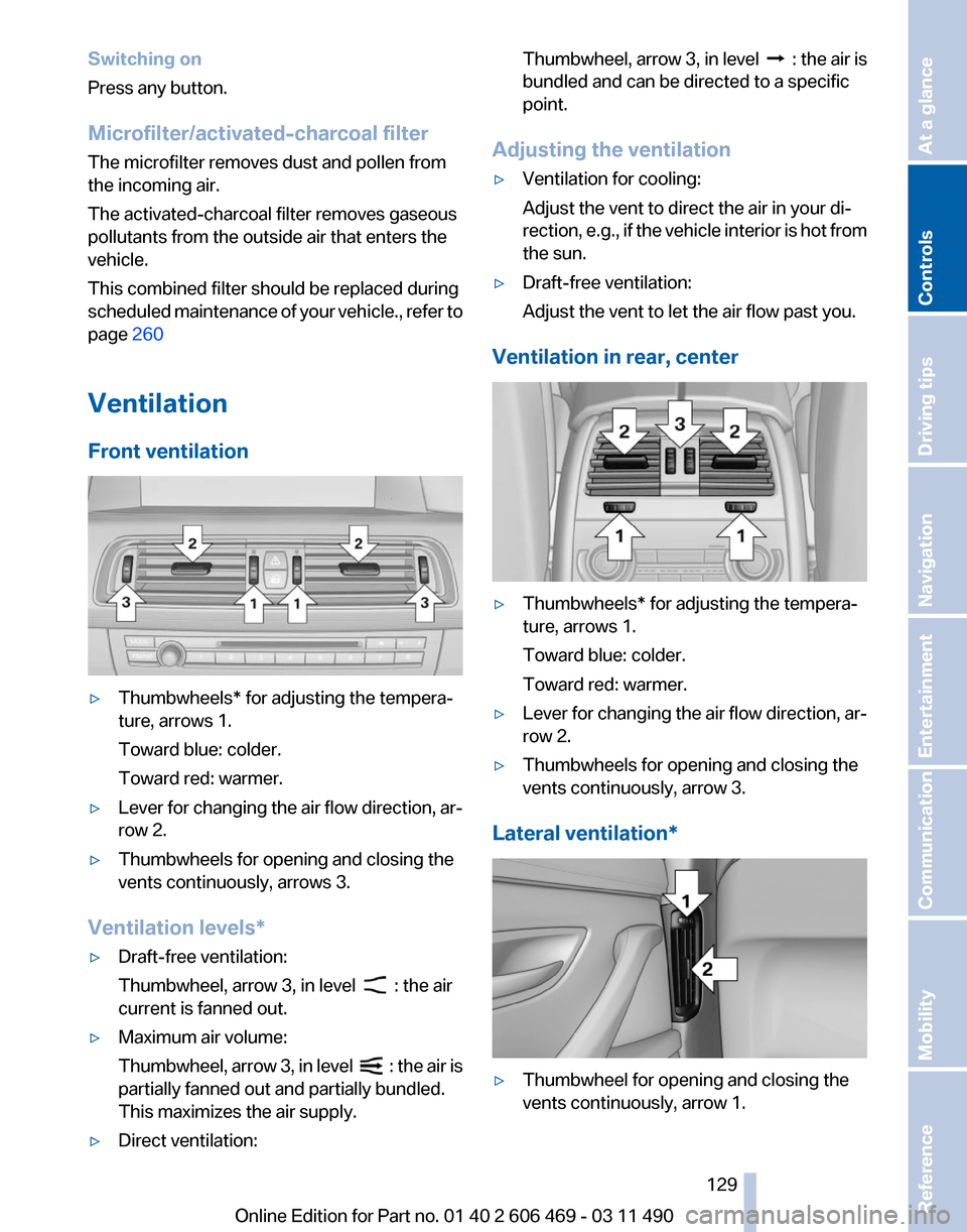
Front ventilation ▷
Thumbwheels* for adjusting the tempera‐
ture, arrows 1.
Toward blue: colder.
Toward red: warmer.
▷ Lever for changing the air flow direction, ar‐
row 2.
▷ Thumbwheels for opening and closing the
vents continuously, arrows 3.
Ventilation levels*
▷ Draft-free ventilation:
Thumbwheel, arrow 3, in level : the air
current is fanned out.
▷ Maximum air volume:
Thumbwheel,
arrow 3, in level : the air is
partially fanned out and partially bundled.
This maximizes the air supply.
▷ Direct ventilation: Thumbwheel, arrow 3, in level :
the air is
bundled and can be directed to a specific
point.
Adjusting the ventilation
▷ Ventilation for cooling:
Adjust the vent to direct the air in your di‐
rection,
e.g., if the vehicle interior is hot from
the sun.
▷ Draft-free ventilation:
Adjust the vent to let the air flow past you.
Ventilation in rear, center ▷
Thumbwheels* for adjusting the tempera‐
ture, arrows 1.
Toward blue: colder.
Toward red: warmer.
▷ Lever for changing the air flow direction, ar‐
row 2.
▷ Thumbwheels for opening and closing the
vents continuously, arrow 3.
Lateral ventilation* ▷
Thumbwheel for opening and closing the
vents continuously, arrow 1.
Seite 129
129Online Edition for Part no. 01 40 2 606 469 - 03 11 490
Reference Mobility Communication Entertainment Navigation Driving tips
Controls At a glance
Page 133 of 304

To do so:
▷
Read the instructions of the hand-held
transmitter.
▷ Press the memory button of the universal
remote control for an extended period.
If the LED flashes rapidly for a brief period and
then lights up continuously for approx. 2 sec‐
onds, the hand-held transmitter is equipped
with an alternating code system.
In this case, program the memory buttons as
described under Alternating-code hand-held
transmitters.
Alternating-code hand-held
transmitters
Please obtain information on synchronizing the
device
in the operating manual of the device be‐
ing set up.
Programming will be easier with the aid of a sec‐
ond person.
1. Park the vehicle within range of the remote-
controlled device.
2. Program the universal remote control as de‐
scribed above under Fixed-code hand-held
transmitters.
3. Press and hold the programmed button on
the
interior rearview mirror for approx. 5 sec‐
onds until the device to be adjusted is acti‐
vated.
If the device does not become activated,
press and hold the button and watch the
LED:
▷ If the LED lights up continuously, the
programming is completed. The device
should
become activated when the but‐
ton is pressed briefly.
▷ If the LED flashes for approx. 2 seconds
and then lights up continuously, con‐
tinue the programming procedure be‐
ginning with step 4.
4. Locate the button on the receiver of the de‐
vice to be set, e.g., on the drive. 5.
Press the button on the receiver of the de‐
vice
to be set. You have approx. 30 seconds
for the next step.
6. Press the programmed memory button of
the universal remote control three times.
The device can be operated when the engine is
running or the ignition is switched on.
Reassigning individual programs
1. Switch on the ignition.
2. Hold the hand-held transmitter a distance of
approx.
2 to 8 in/5 to 20 cm from the memory
buttons.
3. Press the memory button of the universal
remote control.
4. If the LED flashes slowly after approx.
20 seconds, press the transmit button on
the hand-held transmitter.
5. Release both buttons when the LED flashes
rapidly.
If
the LED does not flash rapidly after approx.
15 seconds, change the distance and repeat
the step.
Deleting all stored programs
Press the left and right memory buttons for ap‐
prox. 20 seconds until the LED flashes rapidly.
All stored programs are deleted.
The programs cannot be deleted individually.
Seite 133
133Online Edition for Part no. 01 40 2 606 469 - 03 11 490
Reference Mobility Communication Entertainment Navigation Driving tips
Controls At a glance
Page 135 of 304

Rear
Opening
Press on the cover.
Emptying
Take out the insert.
Lighter
Push in the lighter.
The lighter can be removed as soon as it pops
back out.
Danger of burns
Only hold the hot lighter by its knob; oth‐
erwise, there is the danger of getting burned.
Take the remote control with you when leaving
the vehicle so that children cannot use the
lighter and burn themselves.◀
Connecting
electrical devices
Sockets*
The lighter socket can be used as a socket for
electrical equipment while the engine is running
or when the ignition is switched on. The total load of all sockets must not exceed 140 Watt at
12 V.
Do not damage the socket by using unsuitable
connectors.
Front center console: manual
transmission
Press on the cover.
Remove the cover or cigarette lighter*.
Front center console:
automatic
transmission* Press on the cover.
Remove the cover or cigarette lighter*.
Center armrest*
Remove the cover.
Seite 135
135Online Edition for Part no. 01 40 2 606 469 - 03 11 490
Reference Mobility Communication Entertainment Navigation Driving tips
Controls At a glance
Page 137 of 304

Ensure that the lock is securely en‐
gaged
When
folding back the backrest, be sure that
it locks in place securely. If it is not properly
engaged, transported cargo could enter the
passenger compartment during braking or
evasive maneuvers and endanger the vehi‐
cle occupants.◀ 2.
Release the latch plate from the fixture on
the rear window shelf and insert it into the
belt
lock of the center safety belt. Make sure
you hear the latch plate engage.
To secure cargo, refer to page 149,
with nets or
draw straps, the cargo area is fitted with lashing
eyes.
Ski bag*
Capacity
The ski bag can be used to transport up to four
pairs of skis with a length of up to 6 ft/2.10 m or,
depending on the binding, up to two snow‐
boards with a length of up to 5 ft/1.60 m.
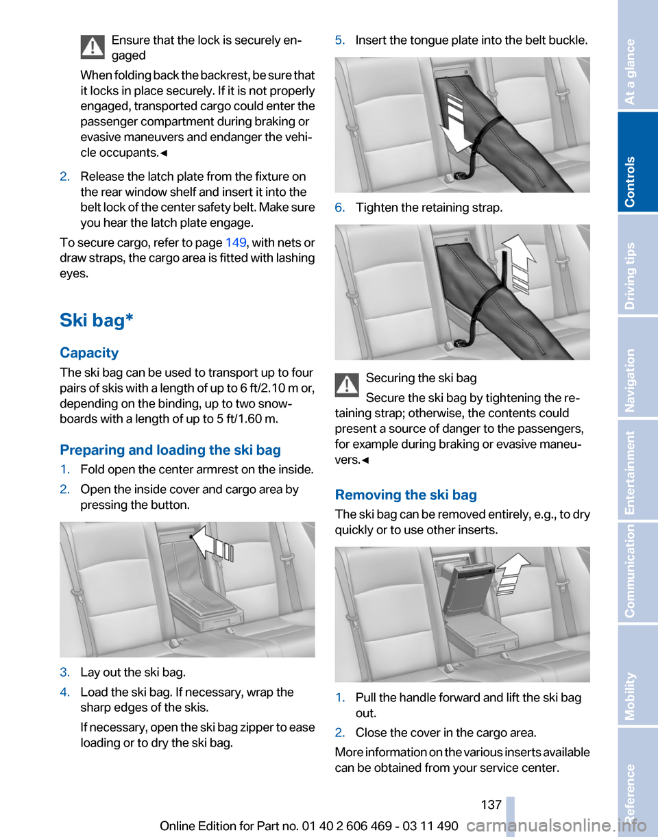
Preparing and loading the ski bag
1. Fold open the center armrest on the inside.
2. Open the inside cover and cargo area by
pressing the button. 3.
Lay out the ski bag.
4. Load the ski bag. If necessary, wrap the
sharp edges of the skis.
If
necessary, open the ski bag zipper to ease
loading or to dry the ski bag. 5.
Insert the tongue plate into the belt buckle. 6.
Tighten the retaining strap. Securing the ski bag
Secure the ski bag by tightening the re‐
taining strap; otherwise, the contents could
present a source of danger to the passengers,
for example during braking or evasive maneu‐
vers.◀
Removing the ski bag
The
ski bag can be removed entirely, e.g., to dry
quickly or to use other inserts. 1.
Pull the handle forward and lift the ski bag
out.
2. Close the cover in the cargo area.
More information on the various inserts available
can be obtained from your service center. Seite 137
137Online Edition for Part no. 01 40 2 606 469 - 03 11 490
Reference Mobility Communication Entertainment Navigation Driving tips
Controls At a glance