2011 Alfa Romeo MiTo Owner handbook (in English)
-
 1
1 -
 2
2 -
 3
3 -
 4
4 -
 5
5 -
 6
6 -
 7
7 -
 8
8 -
 9
9 -
 10
10 -
 11
11 -
 12
12 -
 13
13 -
 14
14 -
 15
15 -
 16
16 -
 17
17 -
 18
18 -
 19
19 -
 20
20 -
 21
21 -
 22
22 -
 23
23 -
 24
24 -
 25
25 -
 26
26 -
 27
27 -
 28
28 -
 29
29 -
 30
30 -
 31
31 -
 32
32 -
 33
33 -
 34
34 -
 35
35 -
 36
36 -
 37
37 -
 38
38 -
 39
39 -
 40
40 -
 41
41 -
 42
42 -
 43
43 -
 44
44 -
 45
45 -
 46
46 -
 47
47 -
 48
48 -
 49
49 -
 50
50 -
 51
51 -
 52
52 -
 53
53 -
 54
54 -
 55
55 -
 56
56 -
 57
57 -
 58
58 -
 59
59 -
 60
60 -
 61
61 -
 62
62 -
 63
63 -
 64
64 -
 65
65 -
 66
66 -
 67
67 -
 68
68 -
 69
69 -
 70
70 -
 71
71 -
 72
72 -
 73
73 -
 74
74 -
 75
75 -
 76
76 -
 77
77 -
 78
78 -
 79
79 -
 80
80 -
 81
81 -
 82
82 -
 83
83 -
 84
84 -
 85
85 -
 86
86 -
 87
87 -
 88
88 -
 89
89 -
 90
90 -
 91
91 -
 92
92 -
 93
93 -
 94
94 -
 95
95 -
 96
96 -
 97
97 -
 98
98 -
 99
99 -
 100
100 -
 101
101 -
 102
102 -
 103
103 -
 104
104 -
 105
105 -
 106
106 -
 107
107 -
 108
108 -
 109
109 -
 110
110 -
 111
111 -
 112
112 -
 113
113 -
 114
114 -
 115
115 -
 116
116 -
 117
117 -
 118
118 -
 119
119 -
 120
120 -
 121
121 -
 122
122 -
 123
123 -
 124
124 -
 125
125 -
 126
126 -
 127
127 -
 128
128 -
 129
129 -
 130
130 -
 131
131 -
 132
132 -
 133
133 -
 134
134 -
 135
135 -
 136
136 -
 137
137 -
 138
138 -
 139
139 -
 140
140 -
 141
141 -
 142
142 -
 143
143 -
 144
144 -
 145
145 -
 146
146 -
 147
147 -
 148
148 -
 149
149 -
 150
150 -
 151
151 -
 152
152 -
 153
153 -
 154
154 -
 155
155 -
 156
156 -
 157
157 -
 158
158 -
 159
159 -
 160
160 -
 161
161 -
 162
162 -
 163
163 -
 164
164 -
 165
165 -
 166
166 -
 167
167 -
 168
168 -
 169
169 -
 170
170 -
 171
171 -
 172
172 -
 173
173 -
 174
174 -
 175
175 -
 176
176 -
 177
177 -
 178
178 -
 179
179 -
 180
180 -
 181
181 -
 182
182 -
 183
183 -
 184
184 -
 185
185 -
 186
186 -
 187
187 -
 188
188 -
 189
189 -
 190
190 -
 191
191 -
 192
192 -
 193
193 -
 194
194 -
 195
195 -
 196
196 -
 197
197 -
 198
198 -
 199
199 -
 200
200 -
 201
201 -
 202
202 -
 203
203 -
 204
204 -
 205
205 -
 206
206 -
 207
207 -
 208
208 -
 209
209 -
 210
210 -
 211
211 -
 212
212 -
 213
213 -
 214
214 -
 215
215 -
 216
216 -
 217
217 -
 218
218 -
 219
219 -
 220
220 -
 221
221 -
 222
222 -
 223
223 -
 224
224 -
 225
225 -
 226
226 -
 227
227 -
 228
228 -
 229
229 -
 230
230 -
 231
231 -
 232
232 -
 233
233 -
 234
234 -
 235
235 -
 236
236 -
 237
237 -
 238
238 -
 239
239 -
 240
240 -
 241
241 -
 242
242 -
 243
243 -
 244
244 -
 245
245 -
 246
246 -
 247
247 -
 248
248 -
 249
249 -
 250
250 -
 251
251 -
 252
252 -
 253
253 -
 254
254 -
 255
255 -
 256
256 -
 257
257 -
 258
258 -
 259
259 -
 260
260 -
 261
261
 15
7.5
7.5
15
15
15
5
5
5
192IN AN EMERGENCY
F14
F12
F13
F12
F13
F30
F37
F51
F3241
43
43
43
43
41
43
43
43
FUSE SUMMARY TABLE
LIGHTS FUSE AMPERE FIGURE
Main beams
Right hand dipped beam headlight
Left")
 41
41
41
43
41
41
41
41
43
43
4315
20
15
7.5
30
7.5
30
15
5
10
5F08
F09
F10
F13
F15
F19
F20
F21
F31
F36
F37
IN AN EMERGENCY193
4
CONSUMERS FUSE AMPERE FIGURE
Heated windscreen
Headlight washer pump
Tw")
 F38
F43
F47
F48
F4915
20
20
20
543
43
43
43
43
194IN AN EMERGENCY
CONSUMERS FUSE AMPERE FIGURE
Door lock motor on door,
Safe Lock motor on doors,
Tailgate unlocking motor
Windscreen / rearscreen washe")
 43
43
45
45
45
45
45
45
41
41
415
5
15
10
15
20
–
15
40
15
7.5F51
F53
F4
F5
F6
F1
F2
F3
F83
F85
F87
IN AN EMERGENCY195
4
CONSUMERS FUSE AMPERE FIGURE
Clutch switch, Brake light
switch, relay coils o")
 196IN AN EMERGENCY
RECHARGING THE BATTERY
IMPORTANT The battery recharging procedure is provided as an ex-
ample only. Contact an Alfa Romeo Authorised Services to carry
out this operation.
We recomme")
 IN AN EMERGENCY197
4
VERSIONS WITH Start&Stop SYSTEM
(with dummy pole) fig. 46
(for versions/markets, where provided)
To charge, proceed as follows:
❍disconnect the quick-release negative terminal A")
 198IN AN EMERGENCY
VERSIONS WITH Start&Stop SYSTEM
(without dummy pole) fig. 47
(for versions/markets, where provided)
To charge, proceed as follows:
❍disconnect the connector A (pressing the button")
 IN AN EMERGENCY199
4
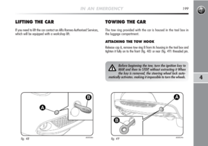
LIFTING THE CAR
If you need to lift the car contact an Alfa Romeo Authorised Services,
which will be equipped with a workshop lift.
TOWING THE CAR
The tow ring provided with the c")