Page 49 of 86
PERIODIC MAINTENANCE AND ADJUSTMENT
6-16
6
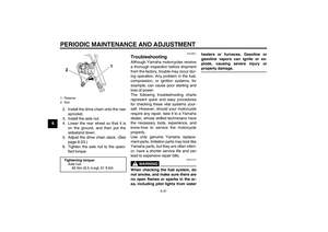
TIPIf the specified idling speed cannot be
obtained as described above, have a
Yamaha dealer make the adjustment.3. Install the panel.
EAU21372
Adjusting the throttle cable
free play The throttle cable free play should mea-
sure 3.0–5.0 mm (0.12–0.20 in) at the
throttle grip. Periodically check the
throttle cable free play and, if neces-
sary, adjust it as follows.TIPThe engine idling speed must be cor-
rectly adjusted before checking and ad-
justing the throttle cable free play.1. Loosen the locknut.2. To increase the throttle cable free
play, turn the adjusting nut in direc-
tion (a). To decrease the throttle
cable free play, turn the adjusting
nut in direction (b).
3. Tighten the locknut.
1. Idle adjusting screwEngine idling speed:
1300–1500 r/min
1. Throttle cable free play
1. Locknut
2. Adjusting nut
U5D7E1E0.book Page 16 Monday, July 13, 2009 11:55 AM
Page 50 of 86

PERIODIC MAINTENANCE AND ADJUSTMENT
6-17
6
EAU21401
Valve clearance The valve clearance changes with use,
resulting in improper air-fuel mixture
and/or engine noise. To prevent this
from occurring, the valve clearance
must be adjusted by a Yamaha dealer
at the intervals specified in the periodic
maintenance and lubrication chart.
EAUM2401
Tires To maximize the performance, durabil-
ity, and safe operation of your motorcy-
cle, note the following points regarding
the specified tires.
Tire air pressure
The tire air pressure should be checked
and, if necessary, adjusted before each
ride.
WARNING
EWA10501
Operation of this vehicle with im-
proper tire pressure may cause se-
vere injury or death from loss of
control.�
The tire air pressure must be
checked and adjusted on cold
tires (i.e., when the temperature
of the tires equals the ambient
temperature).
�
The tire air pressure must be ad-
justed in accordance with the
riding speed and with the total
weight of rider, passenger, car-
go, and accessories approved
for this model.
WARNING
EWA10511
Never overload your vehicle. Opera-
tion of an overloaded vehicle could
cause an accident.Tire air pressure (measured on cold
tires):
0–90 kg (0–198 lb):
Front:
175 kPa (1.75 kgf/cm², 25 psi)
Rear:
200 kPa (2.00 kgf/cm², 29 psi)
90–185 kg (198–408 lb):
Front:
175 kPa (1.75 kgf/cm², 25 psi)
Rear:
225 kPa (2.25 kgf/cm², 33 psi)
Maximum load*:
185 kg (408 lb)
* Total weight of rider, passenger, car-
go and accessories
U5D7E1E0.book Page 17 Monday, July 13, 2009 11:55 AM
Page 51 of 86

PERIODIC MAINTENANCE AND ADJUSTMENT
6-18
6 Tire inspection
The tires must be checked before each
ride. If the center tread depth reaches
the specified limit, if the tire has a nail or
glass fragments in it, or if the sidewall is
cracked, have a Yamaha dealer re-
place the tire immediately.
TIPThe tire tread depth limits may differ
from country to country. Always comply
with the local regulations.
WARNING
EWA10470
�
Have a Yamaha dealer replace
excessively worn tires. Besides
being illegal, operating the vehi-
cle with excessively worn tires
decreases riding stability and
can lead to loss of control.
�
The replacement of all wheel
and brake related parts, includ-
ing the tires, should be left to a
Yamaha dealer, who has the
necessary professional knowl-
edge and experience.
Tire informationThis motorcycle is equipped with cast
wheels and tubeless tires with valves.
WARNING
EWA10901
�
The front and rear tires should
be of the same make and de-
sign, otherwise the handling
characteristics of the motorcy-
cle may be different, which
could lead to an accident.
�
Always make sure that the valve
caps are securely installed to
prevent air pressure leakage.
�
Use only the tire valves and
valve cores listed below to
avoid tire deflation during a ride.
After extensive tests, only the tires list-
ed below have been approved for this
model by Yamaha Motor Co., Ltd.
1. Tire sidewall
2. Tire tread depthMinimum tire tread depth (front and
rear):
1.6 mm (0.06 in)
1. Tire air valve
2. Tire air valve core
3. Tire air valve cap with seal
123
U5D7E1E0.book Page 18 Monday, July 13, 2009 11:55 AM
Page 52 of 86

PERIODIC MAINTENANCE AND ADJUSTMENT
6-19
6
WARNING
EWA10600
This motorcycle is fitted with super-
high-speed tires. Note the following
points in order to make the most ef-
ficient use of these tires.�
Use only the specified replace-
ment tires. Other tires may run
the danger of bursting at super
high speeds.
�
Brand-new tires can have a rela-
tively poor grip on certain road
surfaces until they have been
“broken in”. Therefore, it is ad-
visable before doing any high-
speed riding to ride conserva-
tively for approximately 100 km
(60 mi) after installing a new tire.
�
The tires must be warmed up
before a high-speed run.
�
Always adjust the tire air pres-
sure according to the operating
conditions.
EAU21960
Cast wheels To maximize the performance, durabil-
ity, and safe operation of your vehicle,
note the following points regarding the
specified wheels.�
The wheel rims should be checked
for cracks, bends or warpage be-
fore each ride. If any damage is
found, have a Yamaha dealer re-
place the wheel. Do not attempt
even the smallest repair to the
wheel. A deformed or cracked
wheel must be replaced.
�
The wheel should be balanced
whenever either the tire or wheel
has been changed or replaced. An
unbalanced wheel can result in
poor performance, adverse han-
dling characteristics, and a short-
ened tire life.
�
Ride at moderate speeds after
changing a tire since the tire sur-
face must first be “broken in” for it
to develop its optimal characteris-
tics.
Front tire:
Size:
100/80-17 M/C 52H
Manufacturer/model:
PIRELLI/SPORT DEMON
MICHELIN/PILOT SPORTY
Tire air valve:
TR412
Va l ve c o r e :
V3002 (original)
Rear tire:
Size:
130/70-17 M/C 62H
Manufacturer/model:
PIRELLI/SPORT DEMON
MICHELIN/PILOT SPORTY
Tire air valve:
TR412
Va l ve c o r e :
V3002 (original)
U5D7E1E0.book Page 19 Monday, July 13, 2009 11:55 AM
Page 53 of 86
 as
shown. Periodically check the c")
PERIODIC MAINTENANCE AND ADJUSTMENT
6-20
6
EAU22043
Adjusting the clutch lever free
play The clutch lever free play should mea-
sure 10.0–15.0 mm (0.39–0.59 in) as
shown. Periodically check the clutch le-
ver free play and, if necessary, adjust it
as follows.
1. Slide the rubber cover back at the
clutch lever.
2. Loosen the locknut.
3. To increase the clutch lever free
play, turn the adjusting bolt in di-
rection (a). To decrease the clutch
lever free play, turn the adjusting
bolt in direction (b).
TIPIf the specified clutch lever free play
could be obtained as described above,
skip steps 4–7.4. Fully turn the adjusting bolt at the
clutch lever in direction (a) to loos-
en the clutch cable.
5. Loosen the locknut at the crank-
case.
6. To increase the clutch lever free
play, turn the adjusting nut in direc-
tion (a). To decrease the clutch le-
ver free play, turn the adjusting nut
in direction (b).7. Tighten the locknut at the crank-
case.
8. Tighten the locknut at the clutch le-
ver and then slide the rubber cover
to its original position.
1. Clutch lever free play adjusting bolt
2. Clutch lever free play
1. Locknut
2. Clutch lever free play adjusting nut (crank-
case)
U5D7E1E0.book Page 20 Monday, July 13, 2009 11:55 AM
Page 54 of 86
 as
shown. Periodically check the")
PERIODIC MAINTENANCE AND ADJUSTMENT
6-21
6
EAUT1221
Checking the front brake lever
free play The brake lever free play should mea-
sure 2.0–5.0 mm (0.08–0.20 in) as
shown. Periodically check the brake le-
ver free play and, if necessary, have a
Yamaha dealer check the brake sys-
tem.
WARNING
EWA10641
An incorrect brake lever free play in-
dicates a hazardous condition in the
brake system. Do not operate the ve-
hicle until the brake system has
been checked or repaired by a
Yamaha dealer.
EAUM1353
Adjusting the brake pedal free
play The brake pedal free play should mea-
sure 3.5–4.5 mm (0.14–0.18 in) as
shown. Periodically check the brake
pedal free play and, if necessary, have
a Yamaha dealer adjust it.
WARNING
EWAM1030
An incorrect brake pedal free play
indicates a hazardous condition in
the brake system. Do not operate the
motorcycle until the brake system
has been checked or repaired by a
Yamaha dealer.
EAU22392
Checking the front and rear
brake pads The front and rear brake pads must be
checked for wear at the intervals spec-
ified in the periodic maintenance and
lubrication chart.
EAU22440
Front brake pads
1. Remove the front brake caliper by
removing the bolts.
2. Check each front brake pad for
damage and measure the lining
thickness. If a brake pad is dam-
aged or if the lining thickness is
1. Brake lever free play
1. Brake pedal free play
1. Bolt
2. Brake caliper
3. Lining thickness
U5D7E1E0.book Page 21 Monday, July 13, 2009 11:55 AM
Page 55 of 86
, have a
Yamaha dealer replace the brake
pads as a set.
3. Install the front brake caliper by in-
stalling the bolts, then tighteni")
PERIODIC MAINTENANCE AND ADJUSTMENT
6-22
6 less than 0.8 mm (0.03 in), have a
Yamaha dealer replace the brake
pads as a set.
3. Install the front brake caliper by in-
stalling the bolts, then tightening
them to the specified torque.
EAU22500
Rear brake pads
Check each rear brake pad for damage
and measure the lining thickness. If a
brake pad is damaged or if the lining
thickness is less than 1 mm (0.04 in),
have a Yamaha dealer replace the
brake pads as a set.
EAU22580
Checking the brake fluid level Front brake
Rear brake
Insufficient brake fluid may allow air to
enter the brake system, possibly caus-
ing it to become ineffective.Before riding, check that the brake fluid
is above the minimum level mark and
replenish if necessary. A low brake fluid
level may indicate worn brake pads
and/or brake system leakage. If the
brake fluid level is low, be sure to check
the brake pads for wear and the brake
system for leakage.
Observe these precautions:
�
When checking the fluid level,
make sure that the top of the brake
fluid reservoir is level.
�
Use only the recommended quality
brake fluid, otherwise the rubber
seals may deteriorate, causing
leakage and poor braking perfor-
mance.
�
Refill with the same type of brake
fluid. Mixing fluids may result in a
harmful chemical reaction and
lead to poor braking performance.
Tightening torque:
Brake caliper bolt:
30 Nm (3.0 m·kgf, 22 ft·lbf)1. Lining thickness
1. Minimum level mark
1. Minimum level mark
Recommended brake fluid:
DOT 4
U5D7E1E0.book Page 22 Monday, July 13, 2009 11:55 AM
Page 56 of 86

PERIODIC MAINTENANCE AND ADJUSTMENT
6-23
6
�
Be careful that water does not en-
ter the brake fluid reservoir when
refilling. Water will significantly
lower the boiling point of the fluid
and may result in vapor lock.
�
Brake fluid may deteriorate paint-
ed surfaces or plastic parts. Al-
ways clean up spilled fluid
immediately.
�
As the brake pads wear, it is nor-
mal for the brake fluid level to grad-
ually go down. However, if the
brake fluid level goes down sud-
denly, have a Yamaha dealer
check the cause.
EAUM1360
Changing the brake fluid Have a Yamaha dealer change the
brake fluid at the intervals specified in
the periodic maintenance and lubrica-
tion chart. In addition, have the brake
hose replaced every four years or
whenever it is damaged or leaking.
EAU22760
Drive chain slack The drive chain slack should be
checked before each ride and adjusted
if necessary.
EAU22773
To check the drive chain slack
1. Place the motorcycle on the side-
stand.TIPWhen checking and adjusting the drive
chain slack, there should be no weight
on the motorcycle.2. Shift the transmission into the neu-
tral position.
3. Move the rear wheel by pushing
the motorcycle to locate the tight-
est portion of the drive chain, and
then measure the drive chain slack
as shown.Drive chain slack:
30.0–40.0 mm (1.18–1.57 in)
U5D7E1E0.book Page 23 Monday, July 13, 2009 11:55 AM