Page 17 of 86
 automati-
cally switch on or off according to
the coolant temperature in the ra-
diator.
�
If the")
INSTRUMENT AND CONTROL FUNCTIONS
3-3
3
TIP�
For radiator-fan-equipped vehi-
cles, the radiator fan(s) automati-
cally switch on or off according to
the coolant temperature in the ra-
diator.
�
If the engine overheats, see page
6-38 for further instructions.
EAUT1934
Engine trouble warning light“”
This warning light flashes or stays on if
an electrical circuit monitoring the en-
gine is not working correctly. If this oc-
curs, have a Yamaha dealer check the
self-diagnosis system.
The electrical circuit of the warning light
can be checked by turning the key to
“ON”. The warning light should come
on for a few seconds, and then go off.
If the warning light does not come on
initially when the key is turned to “ON”,
or if the warning light remains on, have
a Yamaha dealer check the electrical
circuit.
EAU11872
Tachometer The electric tachometer allows the rider
to monitor the engine speed and keep it
within the ideal power range.
When the key is turned to “ON”, the ta-
chometer needle will sweep once
across the r/min range and then return
to zero r/min in order to test the electri-
cal circuit.NOTICE
ECA10031
Do not operate the engine in the ta-
chometer red zone.
Red zone: 10000 r/min and above
EAUM2303
Multi-function display
WARNING
EWA12312
Be sure to stop the vehicle before
making any setting changes to the
multi-function display. Changing
settings while riding can distract the
operator and increase the risk of an
accident.The multi-function display is equipped
with the following:�
a speedometer (which shows the
riding speed)
�
an odometer (which shows the to-
tal distance traveled)
1. Tachometer
2. Tachometer red zone
1. Multi-function display
2.“RESET/SELECT” button
U5D7E1E0.book Page 3 Monday, July 13, 2009 11:55 AM
Page 18 of 86

�
a fuel reserve tripmeter (which
shows the distance traveled since
the fuel")
INSTRUMENT AND CONTROL FUNCTIONS
3-4
3
�
two tripmeters (which show the
distance traveled since they were
last set to zero)
�
a fuel reserve tripmeter (which
shows the distance traveled since
the fuel level warning light came
on)
�
a fuel meter
TIP�
Be sure to turn the key to “ON” be-
fore using the “RESET/ SELECT”
button.
�
For the U.K. only: To switch the
speedometer and odometer/trip-
meter displays between kilometers
and miles, press the “RESET/SE-
LECT” button for at least eight sec-
onds.
Odometer and tripmeter modes
A brief push (less than one second) on
the “RESET/SELECT” button switches
the display between the odometer
mode “ODO” and the tripmeter modes
“TRIP 1” and “TRIP 2” in the following
order:
ODO → TRIP 1 → TRIP 2 → ODOWhen approximately 1.6 L (0.42 US
gal, 0.35 Imp.gal) of fuel remains in the
fuel tank, the odometer display will au-
tomatically change to the fuel reserve
tripmeter mode “F-TRIP” and start
counting the distance traveled from that
point, and the last segment of the fuel
meter will start flashing. In that case,
pushing the “RESET/SELECT” button
switches the display between the vari-
ous tripmeter and odometer modes in
the following order:
F-TRIP → TRIP 1 → TRIP 2 → ODO →
F-TRIP
To reset a tripmeter, select it by push-
ing the “RESET/SELECT” button briefly
(less than one second), and then push
the button again for at least three sec-
onds while the selected tripmeter is
flashing. If you do not reset the fuel re-
serve tripmeter manually, it will reset it-
self automatically and the display will
return to the prior mode after refueling
and traveling 5 km (3 mi).Fuel meter
The fuel meter indicates the amount of
fuel in the fuel tank. The display seg-
ments of the fuel meter disappear to-
wards “E” (Empty) as the fuel level
decreases. When the last fuel meter
segment starts flashing, refuel as soon
as possible.
1. Fuel meter
U5D7E1E0.book Page 4 Monday, July 13, 2009 11:55 AM
Page 19 of 86

INSTRUMENT AND CONTROL FUNCTIONS
3-5
3
EAU12348
Handlebar switches Left
Right
EAU12360
Pass switch “PASS”
Press this switch to flash the headlight.
EAU12400
Dimmer switch“/”
Set this switch to“” for the high
beam and to“” for the low beam.
EAU12460
Turn signal switch“/”
To signal a right-hand turn, push this
switch to“”. To signal a left-hand
turn, push this switch to“”. When re-
leased, the switch returns to the center
position. To cancel the turn signal
lights, push the switch in after it has re-
turned to the center position.
EAU12500
Horn switch“”
Press this switch to sound the horn.
EAU12660
Engine stop switch“/”
Set this switch to“” before starting
the engine. Set this switch to“” to
stop the engine in case of an emergen-
cy, such as when the vehicle overturns
or when the throttle cable is stuck.
EAU12711
Start switch“”
Push this switch to crank the engine
with the starter. See page 5-1 for start-
ing instructions prior to starting the en-
gine.
1. Pass switch “PA S S”
2. Dimmer switch“/”
3. Turn signal switch“/”
4. Horn switch“”
1. Engine stop switch“/”
2. Start switch“”
U5D7E1E0.book Page 5 Monday, July 13, 2009 11:55 AM
Page 20 of 86
INSTRUMENT AND CONTROL FUNCTIONS
3-6
3
EAU12820
Clutch lever The clutch lever is located at the left
handlebar grip. To disengage the
clutch, pull the lever toward the handle-
bar grip. To engage the clutch, release
the lever. The lever should be pulled
rapidly and released slowly for smooth
clutch operation.
The clutch lever is equipped with a
clutch switch, which is part of the igni-
tion circuit cut-off system. (See page
3-11.)
EAU12870
Shift pedal The shift pedal is located on the left
side of the engine and is used in com-
bination with the clutch lever when
shifting the gears of the 6-speed con-
stant-mesh transmission equipped on
this motorcycle.
EAU12890
Brake lever The brake lever is located at the right
handlebar grip. To apply the front
brake, pull the lever toward the handle-
bar grip.
1. Clutch lever
1. Shift pedal
1. Brake lever
U5D7E1E0.book Page 6 Monday, July 13, 2009 11:55 AM
Page 21 of 86
INSTRUMENT AND CONTROL FUNCTIONS
3-7
3
EAU12941
Brake pedal The brake pedal is on the right side of
the motorcycle. To apply the rear
brake, press down on the brake pedal.
EAUM2081
Fuel tank cap To remove the fuel tank cap
1. Open the fuel tank cap lock cover.
2. Insert the key into the lock and turn
it 1/4 turn counterclockwise. The
lock will be released and the fuel
tank cap can be removed.
To install the fuel tank cap
1. Push the fuel tank cap into position
with the key inserted in the lock.
2. Turn the key clockwise to the orig-
inal position, and then remove it.
3. Close the lock cover.
TIPThe fuel tank cap cannot be installed
unless the key is in the lock. In addition,
the key cannot be removed if the cap is
not properly installed and locked.
WARNING
EWA11141
Make sure that the fuel tank cap is
properly installed before riding.
Leaking fuel is a fire hazard.
1. Brake pedal
1. Fuel tank cap lock cover
2. Unlock.
U5D7E1E0.book Page 7 Monday, July 13, 2009 11:55 AM
Page 22 of 86

INSTRUMENT AND CONTROL FUNCTIONS
3-8
3
EAU13212
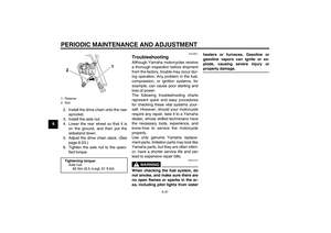
Fuel Make sure there is sufficient gasoline in
the tank.
WARNING
EWA10881
Gasoline and gasoline vapors are
extremely flammable. To avoid fires
and explosions and to reduce the
risk of injury when refueling, follow
these instructions.1. Before refueling, turn off the en-
gine and be sure that no one is sit-
ting on the vehicle. Never refuel
while smoking, or while in the vi-
cinity of sparks, open flames, or
other sources of ignition such as
the pilot lights of water heaters and
clothes dryers.
2. Do not overfill the fuel tank. Stop
filling when the fuel reaches the
bottom of the filler tube. Because
fuel expands when it heats up,
heat from the engine or the sun
can cause fuel to spill out of the
fuel tank.3. Wipe up any spilled fuel immedi-
ately. NOTICE: Immediately wipe
off spilled fuel with a clean, dry,
soft cloth, since fuel may deteri-
orate painted surfaces or plastic
parts.
[ECA10071]
4. Be sure to securely close the fuel
tank cap.
WARNING
EWA15151
Gasoline is poisonous and can
cause injury or death. Handle gaso-
line with care. Never siphon gaso-
line by mouth. If you should swallow
some gasoline or inhale a lot of gas-
oline vapor, or get some gasoline in
your eyes, see your doctor immedi-ately. If gasoline spills on your skin,
wash with soap and water. If gaso-
line spills on your clothing, change
your clothes.
EAU43421
NOTICE
ECA11400
Use only unleaded gasoline. The use
of leaded gasoline will cause severe
damage to internal engine parts,
such as the valves and piston rings,
as well as to the exhaust system.Your Yamaha engine has been de-
signed to use premium unleaded gaso-
line with a research octane number of
95 or higher. If knocking (or pinging) oc-
curs, use a gasoline of a different
1. Fuel tank filler tube
2. Maximum fuel level
Recommended fuel:
PREMIUM UNLEADED GASOLINE
ONLY
Fuel tank capacity:
13.8 L (3.65 US gal, 3.04 Imp.gal)
Fuel reserve amount (when the fuel
level warning indicator flashes):
1.6 L (0.42 US gal, 0.35 Imp.gal)
U5D7E1E0.book Page 8 Monday, July 13, 2009 11:55 AM
Page 23 of 86
INSTRUMENT AND CONTROL FUNCTIONS
3-9
3 brand. Use of unleaded fuel will extend
spark plug life and reduce maintenance
costs.
EAU13445
Catalytic converters This vehicle is equipped with catalytic
converters in the exhaust system.
WARNING
EWA10862
The exhaust system is hot after op-
eration. To prevent a fire hazard or
burns:�
Do not park the vehicle near
possible fire hazards such as
grass or other materials that
easily burn.
�
Park the vehicle in a place
where pedestrians or children
are not likely to touch the hot
exhaust system.
�
Make sure that the exhaust sys-
tem has cooled down before do-
ing any maintenance work.
�
Do not allow the engine to idle
more than a few minutes. Long
idling can cause a build-up of
heat.
NOTICE
ECA10701
Use only unleaded gasoline. The use
of leaded gasoline will cause unre-
pairable damage to the catalytic
converter.
U5D7E1E0.book Page 9 Monday, July 13, 2009 11:55 AM
Page 24 of 86

INSTRUMENT AND CONTROL FUNCTIONS
3-10
3
EAUM2460
Rider seat To remove the rider seat
1. Insert the key into the seat lock,
and then turn it clockwise.
2. Pull the rider seat off.
To install the rider seat
1. Insert the projection on the front of
the rider seat into the seat holder
as shown.2. Push the rear of the rider seat
down to lock it in place.
3. Turn the key counterclockwise,
and then remove it.
TIPMake sure that the rider seat is properly
secured before riding.
EAU15303
Sidestand The sidestand is located on the left side
of the frame. Raise the sidestand or
lower it with your foot while holding the
vehicle upright.TIPThe built-in sidestand switch is part of
the ignition circuit cut-off system, which
cuts the ignition in certain situations.
(See page 3-11 for an explanation of
the ignition circuit cut-off system.)
WARNING
EWA10240
The vehicle must not be ridden with
the sidestand down, or if the side-
stand cannot be properly moved up
(or does not stay up), otherwise the
sidestand could contact the ground
and distract the operator, resulting
in a possible loss of control.
Yamaha’s ignition circuit cut-off
system has been designed to assist
the operator in fulfilling the respon-
sibility of raising the sidestand be-
fore starting off. Therefore, check
this system regularly as described
1. Seat lock
2. Open.
1. Projection
2. Seat holder
U5D7E1E0.book Page 10 Monday, July 13, 2009 11:55 AM