Page 41 of 86

PERIODIC MAINTENANCE AND ADJUSTMENT
6-8
6
EAU18852
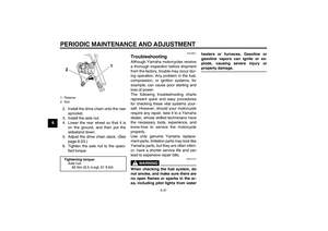
Cowling C
To remove the cowlingRemove the screws, and then pull the
cowling off as shown.
To install the cowlingPlace the cowling in the original posi-
tion, and then install the screws.
EAUM2361
Cowling D
To remove the cowling1. Remove panel A, cowlings A, B
and C.2. Remove the screws and the quick
fasteners, and then take the cowl-
ing off.
TIPThe quick fastener is removed by push-
ing the center pin in with a screwdriver,
then pulling the fastener out.To install the cowling1. Place the cowling in the original
position, and then install the
screws and the quick fasteners.
TIPTo install the quick fasteners, push the
center pin out so that it will protrude
from the fastener head, insert the fas-
tener into the cowling, and then push
the protruding pin in until it is flush with
the fastener head.2. Install cowlings C, B, A and panel
A.
EAUM2370
Panel A
To remove the panel1. Remove the rider seat. (See page
3-10.)
2. Remove the screws, and then take
the panel off.
1. Screw
2. Cowling C
1. Quick fastener
2. Screw
3. Cowling D
U5D7E1E0.book Page 8 Monday, July 13, 2009 11:55 AM
Page 42 of 86

PERIODIC MAINTENANCE AND ADJUSTMENT
6-9
6To install the panel
1. Place the panel in the original posi-
tion, and then install the screws.
2. Install the rider seat.
EAU19632
Checking the spark plug The spark plug is an important engine
component, which is easy to check.
Since heat and deposits will cause any
spark plug to slowly erode, the spark
plug should be removed and checked
in accordance with the periodic mainte-
nance and lubrication chart. In addition,
the condition of the spark plug can re-
veal the condition of the engine.
To remove the spark plug
1. Remove cowling A. (See page
6-7.)
2. Remove the spark plug cap.3. Remove the spark plug as shown,
with the spark plug wrench includ-
ed in the owner’s tool kit.
To check the spark plug
1. Check that the porcelain insulator
around the center electrode of the
spark plug is a medium-to-light tan
(the ideal color when the vehicle is
ridden normally).
TIPIf the spark plug shows a distinctly dif-
ferent color, the engine could be oper-
ating improperly. Do not attempt to
diagnose such problems yourself. In-
stead, have a Yamaha dealer check
the vehicle.
1. Screw
2. Panel A
1. Spark plug cap
1. Spark plug wrench
U5D7E1E0.book Page 9 Monday, July 13, 2009 11:55 AM
Page 43 of 86

PERIODIC MAINTENANCE AND ADJUSTMENT
6-10
6 2. Check the spark plug for electrode
erosion and excessive carbon or
other deposits, and replace it if
necessary.
To install the spark plug
1. Measure the spark plug gap with a
wire thickness gauge and, if nec-
essary, adjust the gap to specifica-
tion.2. Clean the surface of the spark plug
gasket and its mating surface, and
then wipe off any grime from the
spark plug threads.
3. Install the spark plug with the
spark plug wrench, and then tight-
en it to the specified torque.
TIPIf a torque wrench is not available when
installing a spark plug, a good estimate
of the correct torque is 1/4–1/2 turn
past finger tight. However, the spark
plug should be tightened to the speci-
fied torque as soon as possible.4. Install the spark plug cap.
5. Install the cowling.
EAUM2381
Engine oil and oil filter ele-
ment The engine oil level should be checked
before each ride. In addition, the oil
must be changed and the oil filter ele-
ment replaced at the intervals specified
in the periodic maintenance and lubri-
cation chart.
To check the engine oil level
1. Place the vehicle on a level sur-
face and hold it in an upright posi-
tion. A slight tilt to the side can
result in a false reading.
2. Start the engine, warm it up for
several minutes, and then turn it
off.
3. Wait a few minutes until the oil set-
tles, remove the oil filler cap, wipe
the dipstick clean, insert it back
into the oil filler hole (without
screwing it in), and then remove it
again to check the oil level.
NOTICE: Do not operate the ve-
hicle until you know that the en-
gine oil level is sufficient.
[ECA10011]
Specified spark plug:
NGK/CR8E1. Spark plug gapSpark plug gap:
0.7–0.8 mm (0.028–0.031 in)
1
ZAUM0037
Tightening torque:
Spark plug:
12.5 Nm (1.25 m·kgf, 9.0 ft·lbf)
U5D7E1E0.book Page 10 Monday, July 13, 2009 11:55 AM
Page 44 of 86

PERIODIC MAINTENANCE AND ADJUSTMENT
6-11
6
TIPThe engine oil should be between the
minimum and maximum level marks.
4. If the engine oil is below the mini-
mum level mark, add sufficient oil
of the recommended type to raise
it to the correct level.
5. Install the oil filler cap.
To change the engine oil (with or
without oil filter element replace-
ment)
1. Remove cowling D. (See page
6-7.)
2. Start the engine, warm it up for
several minutes, and then turn it
off.
3. Install the engine oil drain attach-
ment, provided with the owner’s
tool kit, under the drain bolt of the
crankcase.4. Place an oil pan under the engine
to collect the used oil.
5. Remove the engine oil filler cap
and the drain bolt along with the O-
ring, compression spring, and en-
gine oil strainer, to drain the oil
from the crankcase. NOTICE:
When removing the engine oil
drain bolt, the O-ring, compres-
sion spring, and oil strainer will
fall out. Take care not to lose
these parts.
[ECA11001]
1. Engine oil filler cap
1. Dipstick
2. Maximum level mark
3. Minimum level mark
1. Engine oil drain bolt (crankcase)
2. Engine oil drain attachment
U5D7E1E0.book Page 11 Monday, July 13, 2009 11:55 AM
Page 45 of 86

PERIODIC MAINTENANCE AND ADJUSTMENT
6-12
6 6. Clean the engine oil strainer with
solvent.
TIPSkip steps 7–9 if the oil filter element is
not being replaced.7. Remove the oil filter element cover
by removing the bolts.8. Remove and replace the oil filter
element and O-ring.
9. Install the oil filter element cover by
installing the bolts, then tightening
them to the specified torque.
TIPMake sure that the O-ring is properly
seated.10. Install the engine oil strainer, com-
pression spring, O-ring and the en-
gine oil drain bolt, and then tighten
it to the specified torque. NOTICE:
Before installing the engine oil
drain bolt, do not forget to in-
stall the O-ring, compression
spring, and oil strainer in posi-
tion.
[ECA10421]
11. Refill with the specified amount of
the recommended engine oil, and
then install and tighten the oil filler
cap.
1. Engine oil drain bolt
2. O-ring
3. Compression spring
4. Strainer
5. Oil pan
1. Bolt
2. Oil filter element cover
1. Oil filter element
2. O-ring
Tightening torques:
Oil filter element cover bolt:
10 Nm (1.0 m·kgf, 7.2 ft·lbf)
Tightening torques:
Engine oil drain bolt:
32 Nm (3.2 m·kgf, 23 ft·lbf)
U5D7E1E0.book Page 12 Monday, July 13, 2009 11:55 AM
Page 46 of 86
, do not
mix any chemical additives. Do
not use oils")
PERIODIC MAINTENANCE AND ADJUSTMENT
6-13
6
NOTICE
ECA11620
�
In order to prevent clutch slip-
page (since the engine oil also
lubricates the clutch), do not
mix any chemical additives. Do
not use oils with a diesel speci-
fication of “CD” or oils of a high-
er quality than specified. In
addition, do not use oils labeled
“ENERGY CONSERVING II” or
higher.
�
Make sure that no foreign mate-
rial enters the crankcase.
12. Start the engine, and then let it idle
for several minutes while checking
it for oil leakage. If oil is leaking, im-
mediately turn the engine off and
check for the cause.13. Turn the engine off, and then
check the oil level and correct it if
necessary.
EAU20070
Coolant The coolant level should be checked
before each ride. In addition, the cool-
ant must be changed at the intervals
specified in the periodic maintenance
and lubrication chart.
EAU20092
To check the coolant level
1. Place the vehicle on a level sur-
face and hold it in an upright posi-
tion.TIP�
The coolant level must be checked
on a cold engine since the level
varies with engine temperature.
�
Make sure that the vehicle is posi-
tioned straight up when checking
the coolant level. A slight tilt to the
side can result in a false reading.
2. Check the coolant level in the cool-
ant reservoir.TIPThe coolant should be between the
minimum and maximum level marks.
Recommended engine oil:
See page 8-1.
Oil quantity:
Without oil filter element replace-
ment:
0.95 L (1.00 US qt, 0.84 Imp.qt)
With oil filter element replacement:
1.00 L (1.06 US qt, 0.88 Imp.qt)
U5D7E1E0.book Page 13 Monday, July 13, 2009 11:55 AM
Page 47 of 86

PERIODIC MAINTENANCE AND ADJUSTMENT
6-14
6 3. If the coolant is at or below the
minimum level mark, remove the
reservoir cap.4. Add coolant to the maximum level
mark, and then install the reservoir
cap. WARNING! Remove only
the coolant reservoir cap. Never
attempt to remove the radiator
cap when the engine is hot.
[EWA15161]
NOTICE: If coolant is not
available, use distilled water or
soft tap water instead. Do not
use hard water or salt water
since it is harmful to the engine.
If water has been used instead
of coolant, replace it with cool-
ant as soon as possible, other-
wise the cooling system will not
be protected against frost and
corrosion. If water has been
added to the coolant, have a
Yamaha dealer check the anti-
freeze content of the coolant as
soon as possible, otherwise the
effectiveness of the coolant will
be reduced.
[ECA10472]EAU33031
Changing the coolant
The coolant must be changed at the in-
tervals specified in the periodic mainte-
nance and lubrication chart. Have a
Yamaha dealer change the coolant.
WARNING! Never attempt to remove
the radiator cap when the engine is
hot.
[EWA10381]
1. Coolant reservoir
2. Maximum level mark
3. Minimum level mark
1. Coolant reservoir cap
Coolant reservoir capacity (up to
the maximum level mark):
0.25 L (0.26 US qt, 0.22 Imp.qt)
U5D7E1E0.book Page 14 Monday, July 13, 2009 11:55 AM
Page 48 of 86

PERIODIC MAINTENANCE AND ADJUSTMENT
6-15
6
EAUM2390
Replacing the air filter element
and cleaning the check hose The air filter element should be re-
placed at the intervals specified in the
periodic maintenance and lubrication
chart. Have a Yamaha dealer replace
the air filter element more frequently if
you are riding in unusually wet or dusty
areas. In addition, the air filter check
hose must be frequently checked and
cleaned if necessary.
To clean the air filter check hose
1. Check the hose on the side of the
air filter case for accumulated dirt
or water.2. If dirt or water is visible, remove
the hose, clean it, and then install
it.
EAU33482
Adjusting the engine idling
speed The engine idling speed must be
checked and, if necessary, adjusted as
follows at the intervals specified in the
periodic maintenance and lubrication
chart.
The engine should be warm before
making this adjustment.
1. Remove panel A. (See page 6-7.)
2. Check the engine idling speed
and, if necessary, adjust it to spec-
ification by turning the idle adjust-
ing screw. To increase the engine
idling speed, turn the screw in di-
rection (a). To decrease the en-
gine idling speed, turn the screw in
direction (b).
1. Air filter check hoseU5D7E1E0.book Page 15 Monday, July 13, 2009 11:55 AM