Page 81 of 230

3-22
CHASSIS
3. Inspect:
• Brake fluid level
Refer to "CHECKING THE
BRAKE FLUID LEVEL" section.
4. Check:
• Brake pedal operation
A softy or spongy feeling→Bleed
brake system.
Refer to "BLEEDING THE HY-
DRAULIC BRAKE SYSTEM" sec-
tion.
CHECKING THE REAR BRAKE
PAD INSULATOR
1. Remove:
• Brake pad
Refer to "CHECKING AND RE-
PLACING THE REAR BRAKE
PADS" section.
2. Inspect:
• Rear brake pad insulator "1"
Damage→Replace.
CHECKING THE BRAKE FLUID
LEVEL
1. Place the brake master cylinder
so that its top is in a horizontal po-
sition.
2. Inspect:
• Brake fluid level
Fluid at lower level→Fill up.
• Use only designated quality
brake fluid to avoid poor brake
performance.
• Refill with same type and brand
of brake fluid; mixing fluids
could result in poor brake perfor-
mance.
• Be sure that water or other con-
taminants do not enter master
cylinder when refilling.
• Clean up spilled fluid immediate-
ly to avoid erosion of painted
surfaces or plastic parts.
a. Lower level
A. Front
B. Rear
CHECKING THE SPROCKET
1. Inspect:
• Sprocket teeth "a"
Excessive wear→Replace.
Replace the drive sprocket, rear
wheel sprocket and drive chain as a
set.
CHECKING THE DRIVE CHAIN
1. Measure:
• Drive chain length (15 links) "a"
Out of specification→Replace.
• While measuring the drive chain
length, push down on the drive
chain to increase its tension.
• Measure the length between drive
chain roller "1" and "16" as shown.
• Perform this measurement at two or
three different places.
2. Remove:
• Drive chain "1"
Remove the drive chain using a drive
chain cutter "2".
3. Clean:
• Drive chain
Brush off as much dirt as possi-
ble. Then clean the drive chain
using the chain cleaner.
This machine has a drive chain
with small rubber O-rings "1" be-
tween the side plates. Steam
cleaning, high-pressure washes,
certain solvent and kerosene can
damage these O-rings.
4. Inspect:
• O-ring "1" (drive chain)
Damage→Replace the drive
chain.
•Roller "2"
• Side plate "3"
Damage/wear→Replace the
drive chain.
5. Check:
• Drive chain stiffness "a"
Clean and oil the drive chain and
hold as illustrated.
Stiff→Replace the drive chain.
6. Install:
• Chain joint "1"
• O-ring "2"
• Drive chain "3"
• Link plate "4" Recommended brake flu-
id:
DOT #4
Drive chain length (15
links):
: 239.3 mm
(9.42 in)
Page 82 of 230

3-23
CHASSIS
When installing the drive chain, apply
the lithium soap base grease on the
chain joint and O-rings.
7. Install:
• Link plate
• Press the link plate onto the chain
joint using a drive chain riveter "5".
• Rivet the end of the chain joint us-
ing a drive chain riveter.
• After riveting the chain joint, make
sure its movement is smooth.
8. Lubricate:
• Drive chain
ADJUSTING THE DRIVE CHAIN
SLACK
1. Elevate the rear wheel by placing
the suitable stand under the en-
gine.
2. Check:
• Drive chain slack "a"
Above the seal guard installation
bolt.
Out of specification→Adjust.
Before checking and/or adjusting, ro-
tate the rear wheel through several
revolutions and check the slack sev-
eral times to find the tightest point.
Check and/or adjust the drive chain
slack with the rear wheel in this "tight
chain" position.
3. Adjust:
• Drive chain slack
Drive chain slack adjustment
steps:
a. Loosen the axle nut "1" and lock-
nuts "2".
b. Adjust the drive chain slack by
turning the adjusters "3".
c. Turn each adjuster exactly the
same amount to maintain correct
axle alignment. (There are marks
"a" on each side of the drive chain
puller alignment.) NOTICE: Im-
proper drive chain slack will
overload the engine as well as
other vital parts of the motorcy-
cle and can lead to chain slip-
page or breakage. To prevent
this from occurring, keep the
drive chain slack within the
specified limits.
Turn the adjuster so that the drive
chain is in line with the sprocket, as
viewed from the rear.
d. Tighten the axle nut while pushing
down the drive chain.
e. Tighten the locknuts.
CHECKING THE FRONT FORK
1. Inspect:
• Front fork smooth action
Operate the front brake and
stroke the front fork.
Unsmooth action/oil leakage→
Repair or replace.
CLEANING THE FRONT FORK OIL
SEAL AND DUST SEAL
1. Remove:
•Protector
• Dust seal "1"
Use a thin screw driver, and be care-
ful not to damage the inner fork tube
and dust seal.
2. Clean:
• Dust seal "a"
• Oil seal "b"
• Clean the dust seal and oil seal af-
ter every run.
• Apply the lithium soap base grease
on the inner tube.
Drive chain lubricant:
SAE 10W-40 motor oil
or suitable chain lubri-
cants
Drive chain slack:
48–58 mm (1.9–2.3 in)
To tighten→Turn the adjuster "3"
counterclockwise.
To loosen→Turn the adjuster "3"
clockwise and push wheel for-
ward.
Axle nut:
125 Nm (12.5 m•kg, 90
ft•lb)
Locknut:
19 Nm (1.9 m•kg, 13
ft•lb)
Page 83 of 230

3-24
CHASSIS
RELIEVING THE FRONT FORK
INTERNAL PRESSURE
If the front fork initial movement feels
stiff during a run, relieve the front fork
internal pressure.
1. Elevate the front wheel by placing
a suitable stand under the engine.
2. Remove the air bleed screw "1"
and release the internal pressure
from the front fork.
3. Install:
• Air bleed screw
ADJUSTING THE FRONT FORK
REBOUND DAMPING FORCE
1. Adjust:
• Rebound damping force
By turning the adjuster "1".
• STANDARD POSITION:
This is the position which is back
by the specific number of clicks
from the fully turned-in position.
Do not force the adjuster past the
minimum or maximum extent of
adjustment. The adjuster may be
damaged.
Always adjust each front fork to
the same setting. Uneven adjust-
ment can cause poor handling and
loss of stability.
ADJUSTING THE FRONT FORK
COMPRESSION DAMPING FORCE
1. Remove:
• Rubber cap
2. Adjust:
• Compression damping force
By turning the adjuster "1".
• STANDARD POSITION:
This is the position which is back
by the specific number of clicks
from the fully turned-in position.
Do not force the adjuster past the
minimum or maximum extent of
adjustment. The adjuster may be
damaged.
Always adjust each front fork to
the same setting. Uneven adjust-
ment can cause poor handling and
loss of stability.
3. Install:
• Rubber cap
CHECKING THE REAR SHOCK
ABSORBER
1. Inspect:
• Swingarm smooth action
Abnormal noise/unsmooth action
→Grease the pivoting points or
repair the pivoting points.
Damage/oil leakage→Replace.
ADJUSTING THE REAR SHOCK
ABSORBER SPRING PRELOAD
1. Elevate the rear wheel by placing
the suitable stand under the en-
gine.
2. Remove:
• Rear frame
3. Measure:
• Spring fitting length
The I.D. mark "a" is marked at the end
of the spring.
4. Adjust:
• Spring preload
Adjustment steps:
a. Loosen the locknut "1". Air bleed screw:
1 Nm (0.1 m•kg, 0.7
ft•lb)
Stiffer "a" →Increase the re-
bound damping force. (Turn
the adjuster "1" in.)
Softer "b" →Decrease the re-
bound damping force. (Turn
the adjuster "1" out.)
Extent of adjustment:
Maximum Minimum
Fully turned in
position20 clicks out
(from maximum
position)
Standard position:
8 clicks out
Stiffer "a" →Increase the com-
pression damping force. (Turn
the adjuster "1" in.)
Softer "b" →Decrease the com-
pression damping force. (Turn
the adjuster "1" out.)
Extent of adjustment:
Maximum Minimum
Fully turned in
position20 clicks out
(from maximum
position)
Standard position:
9 clicks out
Standard fitting length:
I.D. MARK/Q'TY Length
Pink/1 252.5 mm
(9.94 in)
* 251.5 mm
(9.90 in)
* For EUROPE
Page 84 of 230

3-25
CHASSIS
b. Loosen the adjuster "2" until there
is some clearance between the
spring and adjuster.
c. Measure the spring free length
"a".
d. Turn the adjuster "2".
• Be sure to remove all dirt and mud
from around the locknut and adjust-
er before adjustment.
• The length of the spring (installed)
changes 1.5 mm (0.06 in) per turn
of the adjuster.
Never attempt to turn the adjuster
beyond the maximum or minimum
setting.
e. Tighten the locknut.
5. Install:
• Rear frame (upper)
• Rear frame (lower)ADJUSTING THE REAR SHOCK
ABSORBER REBOUND DAMPING
FORCE
1. Adjust:
• Rebound damping force
By turning the adjuster "1".
• STANDARD POSITION:
This is the position which is back
by the specific number of clicks
from the fully turned-in position.
(Which align the punch mark "a"
on the adjuster with the punch
mark "b" on the bracket.)
Do not force the adjuster past the
minimum or maximum extent of
adjustment. The adjuster may be
damaged.
ADJUSTING THE REAR SHOCK
ABSORBER LOW COMPRESSION
DAMPING FORCE
1. Adjust:
• Low compression damping force
By turning the adjuster "1".
• STANDARD POSITION:
This is the position which is back
by the specific number of clicks
from the fully turned-in position.
(Which align the punch mark "a"
on the adjuster with the punch
mark "b" on the high compression
damping adjuster.)
Do not force the adjuster past the
minimum or maximum extent of
adjustment. The adjuster may be
damaged.
Stiffer →Increase the spring pre-
load. (Turn the adjuster "2" in.)
Softer→Decrease the spring pre-
load. (Turn the adjuster "2"
out.)
Extent of adjustment:
Maximum Minimum
Position in
which the
spring is turned
in 22 mm (0.87
in) from its free
length.Position in
which the
spring is turned
in 1.5 mm (0.06
in) from its free
length.
Locknut:
30 Nm (3.0 m•kg, 22
ft•lb)
Rear frame (upper):
38 Nm (3.8 m•kg, 27
ft•lb)
Rear frame (lower):
32 Nm (3.2 m•kg, 23
ft•lb)Stiffer "a" →Increase the re-
bound damping force. (Turn
the adjuster "1" in.)
Softer "b" →Decrease the re-
bound damping force. (Turn
the adjuster "1" out.)
Extent of adjustment:
Maximum Minimum
Fully turned in
position20 clicks out
(from maximum
position)
Standard position:
About 11 clicks outStiffer "a" →Increase the low
compression damping force.
(Turn the adjuster "1" in.)
Softer "b" →Decrease the low
compression damping force.
(Turn the adjuster "1" out.)
Extent of adjustment:
Maximum Minimum
Fully turned in
position20 clicks out
(from maximum
position)
Standard position:
About 8 clicks out
* About 9 clicks out
** About 11 clicks out
* For AUS, NZ and ZA
** For EUROPE
Page 85 of 230

3-26
CHASSIS
ADJUSTING THE REAR SHOCK
ABSORBER HIGH COMPRESSION
DAMPING FORCE
1. Adjust:
• High compression damping force
By turning the adjuster "1".
• STANDARD POSITION:
This is the position which is back
by the specific number of turns
from the fully turned-in position.
(Which align the punch mark "a"
on the adjuster with the punch
mark "b" on the adjuster body.)
Do not force the adjuster past the
minimum or maximum extent of
adjustment. The adjuster may be
damaged.
CHECKING THE TIRE PRESSURE
1. Measure:
• Tire pressure
Out of specification→Adjust.
• Check the tire while it is cold.
• Loose bead stoppers allow the tire
to slip off its position on the rim
when the tire pressure is low.
• A tilted tire valve stem indicates that
the tire slips off its position on the
rim.
• If the tire valve stem is found tilted,
the tire is considered to be slipping
off its position. Correct the tire posi-
tion.
CHECKING AND TIGHTENING THE
SPOKES
The following procedure applies to all
of the spokes.
1. Check:
• Spokes
Bend/damage→Replace.
Loose spoke→Retighten.
Tap the spokes with a screw-
driver.
A tight spoke will emit a clear, ringing
tone; a loose spoke will sound flat.
2. Tighten:
• Spokes
(with a spoke nipple wrench "1")
Be sure to retighten these spokes be-
fore and after break-in.
CHECKING THE WHEELS
1. Inspect:
• Wheel runout
Elevate the wheel and turn it.
Abnormal runout→ Replace.
2. Inspect:
• Bearing free play
Exist play→Replace.
CHECKING AND ADJUSTING THE
STEERING HEAD
1. Place a stand under the engine to
raise the front wheel off the
ground. WARNING! Securely
support the vehicle so that
there is no danger of it falling
over.
2. Check:
• Steering stem
Grasp the bottom of the forks and
gently rock the fork assembly
back and forth.
Free play→Adjust steering head.
3. Check:
• Steering smooth action
Turn the handlebar lock to lock.
Unsmooth action→Adjust steer-
ing ring nut. Stiffer "a" →Increase the high
compression damping force.
(Turn the adjuster "1" in.)
Softer "b" →Decrease the high
compression damping force.
(Turn the adjuster "1" out.)
Extent of adjustment:
Maximum Minimum
Fully turned in
position2 turns out
(from maximum
position)
Standard position:
About 1-1/8 turns out
* About 1-1/4 turns out
* For AUS, NZ and ZA
Standard tire pressure:
100 kPa (1.0 kgf/cm
2,
15 psi)
Spoke nipple wrench:
YM-01521/90980-01521
Spokes:
3 Nm (0.3 m•kg, 2.2
ft•lb)
Page 86 of 230

3-27
CHASSIS
4. Adjust:
• Steering ring nut
Steering ring nut adjustment
steps:
a. Remove the headlight.
b. Remove the handlebar and upper
bracket.
c. Loosen the steering ring nut "1"
using the steering nut wrench "2".
d. Tighten the steering ring nut "3"
using steering nut wrench "4".
• Apply the lithium soap base grease
on the thread of the steering stem.
• Set the torque wrench to the steer-
ing nut wrench so that they form a
right angle.
e. Loosen the steering ring nut one
turn.
f. Retighten the steering ring nut us-
ing the steering nut wrench.
Avoid over-tightening.
g. Check the steering stem by turn-
ing it lock to lock. If there is any
binding, remove the steering stem
assembly and inspect the steer-
ing bearings.
h. Install the washer "5", upper
bracket "6", washer "7", steering
stem nut "8", handlebar "9", han-
dlebar upper holder "10" and
headlight "11".
• The handlebar upper holder should
be installed with the punched mark
"a" forward.
• Install the handlebar so that the
marks "b" are in place on both
sides.
• Install the handlebar so that the pro-
jection "c" of the handlebar upper
holder is positioned at the mark on
the handlebar as shown.
• Insert the end of the fuel breather
hose "12" into the hole in the steer-
ing stem.
First tighten the bolts on the front
side of the handlebar upper holder,
and then tighten the bolts on the
rear side.
Steering nut wrench:
YU-33975/90890-01403
Steering nut wrench:
YU-33975/90890-01403
Steering ring nut (initial
tightening):
38 Nm (3.8 m•kg, 27
ft•lb)
Steering ring nut (final
tightening):
7 Nm (0.7 m•kg, 5.1
ft•lb)
Steering stem nut:
145 Nm (14.5 m•kg, 105
ft•lb)
Handlebar upper holder:
28 Nm (2.8 m•kg, 20
ft•lb)
Pinch bolt (upper brack-
et):
21 Nm (2.1 m•kg, 15
ft•lb)
Headlight:
7 Nm (0.7 m•kg, 5.1
ft•lb)
Page 87 of 230
3-28
CHASSIS
LUBRICATION
To ensure smooth operation of all
components, lubricate your machine
during setup, after break-in, and after
every ride.
1. All control cable
2. Clutch lever pivot
3. Shift pedal pivot
4. Footrest pivot
5. Throttle-to-handlebar contact
6. Drive chain
7. Tube guide cable winding por-
tion
8. Throttle cable end
9. Clutch cable end
10. Hot starter cable endA. Use Yamaha cable lube or
equivalent on these areas.
B. Use SAE 10W-40 motor oil or
suitable chain lubricants.
C. Lubricate the following areas
with high quality, lightweight lith-
ium-soap base grease.
Wipe off any excess grease, and
avoid getting grease on the brake
discs.
Page 88 of 230

3-29
ELECTRICAL
ELECTRICAL
CHECKING THE SPARK PLUG
1. Remove:
• Spark plug
2. Inspect:
• Electrode "1"
Wear/damage→Replace.
• Insulator color "2"
Normal condition is a medium to
light tan color.
Distinctly different color→Check
the engine condition.
When the engine runs for many hours
at low speeds, the spark plug insula-
tor will become sooty, even if the en-
gine and carburetor are in good
operating condition.
3. Measure:
• Plug gap "a"
Use a wire gauge or thickness
gauge.
Out of specification→Regap.
4. Clean the plug with a spark plug
cleaner if necessary.
5. Tighten:
• Spark plug
• Before installing a spark plug, clean
the gasket surface and plug sur-
face.
• Finger-tighten "a" the spark plug
before torquing to specification "b".
CHECKING THE IGNITION TIMING
1. Remove:
• Timing mark accessing screw "1"
2. Attach:
• Timing light
• Digital tachometer
To the ignition coil lead (orange
lead"1").
3. Adjust:
• Engine idling speed
Refer to "ADJUSTING THE EN-
GINE IDLING SPEED" section.
4. Check:
• Ignition timing
Visually check the stationary
pointer "a" is within the firing
range "b" on the rotor.
Incorrect firing range→Check ro-
tor and pickup assembly.
5. Install:
• Timing mark accessing screw
CHECKING AND CHARGING THE
BATTERY
Batteries generate explosive hy-
drogen gas and contain electrolyte
which is made of poisonous and
highly caustic sulfuric acid. There-
fore, always follow these preven-
tive measures:
• Wear protective eye gear when
handling or working near batter-
ies.• Charge batteries in a well-venti-
lated area.
• Keep batteries away from fire,
sparks or open flames (e.g.,
welding equipment, lighted ciga-
rettes).
• DO NOT SMOKE when charging
or handling batteries.
• KEEP BATTERIES AND ELEC-
TROLYTE OUT OF REACH OF
CHILDREN.
• Avoid bodily contact with elec-
trolyte as it can cause severe
burns or permanent eye injury.
FIRST AID IN CASE OF BODILY
CONTACT:
EXTERNAL
• Skin — Wash with water.
• Eyes — Flush with water for 15
minutes and get immediate med-
ical attention.
INTERNAL
• Drink large quantities of water or
milk followed with milk of magne-
sia, beaten egg or vegetable oil.
Get immediate medical attention.
Charging time, charging amperage
and charging voltage for an MF
battery are different from those of
conventional batteries. The MF
battery should be charged as ex-
plained in the charging method il-
lustrations. If the battery is
overcharged, the electrolyte level
will drop considerably. Therefore,
take special care when charging
the battery.
Since MF batteries are sealed, it is
not possible to check the charge state
of the battery by measuring the spe-
cific gravity of the electrolyte. There-
fore, the charge of the battery has to
be checked by measuring the voltage
at the battery terminals.
1. Remove:
• Seat
2. Disconnect:
• Battery leads
(from the battery terminals)
First, disconnect the negative bat-
tery lead "1", and then the positive
battery lead "2".
Spark plug gap:
0.7–0.8 mm (0.028–
0.031 in)
Spark plug:
13 Nm (1.3 m•kg, 9.4
ft•lb)
Timing light:
YM-33277-A/90890-
03141
 1
1 2
2 3
3 4
4 5
5 6
6 7
7 8
8 9
9 10
10 11
11 12
12 13
13 14
14 15
15 16
16 17
17 18
18 19
19 20
20 21
21 22
22 23
23 24
24 25
25 26
26 27
27 28
28 29
29 30
30 31
31 32
32 33
33 34
34 35
35 36
36 37
37 38
38 39
39 40
40 41
41 42
42 43
43 44
44 45
45 46
46 47
47 48
48 49
49 50
50 51
51 52
52 53
53 54
54 55
55 56
56 57
57 58
58 59
59 60
60 61
61 62
62 63
63 64
64 65
65 66
66 67
67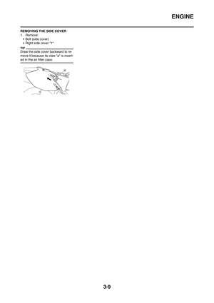 68
68 69
69 70
70 71
71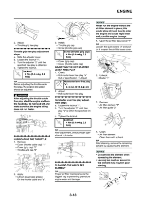 72
72 73
73 74
74 75
75 76
76 77
77 78
78 79
79 80
80 81
81 82
82 83
83 84
84 85
85 86
86 87
87 88
88 89
89 90
90 91
91 92
92 93
93 94
94 95
95 96
96 97
97 98
98 99
99 100
100 101
101 102
102 103
103 104
104 105
105 106
106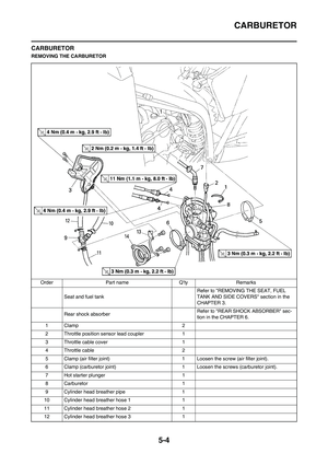 107
107 108
108 109
109 110
110 111
111 112
112 113
113 114
114 115
115 116
116 117
117 118
118 119
119 120
120 121
121 122
122 123
123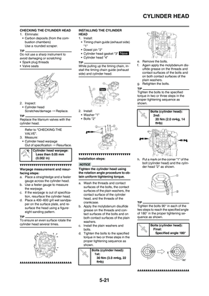 124
124 125
125 126
126 127
127 128
128 129
129 130
130 131
131 132
132 133
133 134
134 135
135 136
136 137
137 138
138 139
139 140
140 141
141 142
142 143
143 144
144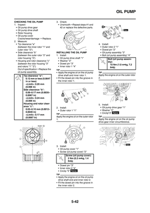 145
145 146
146 147
147 148
148 149
149 150
150 151
151 152
152 153
153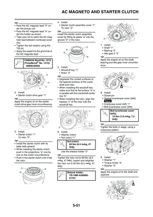 154
154 155
155 156
156 157
157 158
158 159
159 160
160 161
161 162
162 163
163 164
164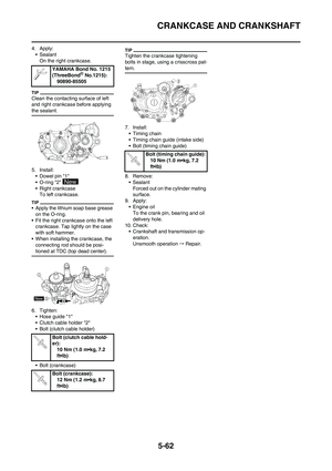 165
165 166
166 167
167 168
168 169
169 170
170 171
171 172
172 173
173 174
174 175
175 176
176 177
177 178
178 179
179 180
180 181
181 182
182 183
183 184
184 185
185 186
186 187
187 188
188 189
189 190
190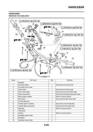 191
191 192
192 193
193 194
194 195
195 196
196 197
197 198
198 199
199 200
200 201
201 202
202 203
203 204
204 205
205 206
206 207
207 208
208 209
209 210
210 211
211 212
212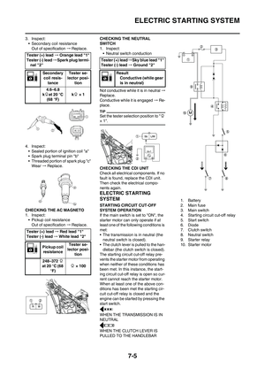 213
213 214
214 215
215 216
216 217
217 218
218 219
219 220
220 221
221 222
222 223
223 224
224 225
225 226
226 227
227 228
228 229
229