Page 73 of 230

3-14
ENGINE
5. Inspect:
• Air filter element
Damage→Replace.
6. Apply:
• Foam-air-filter oil or equivalent oil
to the element
• Squeeze out the excess oil. Ele-
ment should be wet but not drip-
ping.
• Wipe off the oil left on the element
surface using a clean dry cloth. (Ex-
cess oil in the element may ad-
versely affect engine starting.)
7. Install:
• Air filter guide "1"
• Align the projection "a" on filter
guide with the hole "b" in air filter el-
ement.
• Apply the lithium soap base grease
on the matching surface "c" on air
filter element.
8. Install:
• Air filter element "1"
Align the projection "a" on filter guide
with the hole "b" in air filter case.
9. Hook:
•Binder "1"
Hook the binder "1" so that it contacts
the filter guide projections "a".
CHECKING THE ENGINE OIL
LEVEL
1. Stand the machine on a level sur-
face.
• When checking the oil level make
sure that the machine is upright.
• Place the machine on a suitable
stand.
Never remove the oil tank cap just
after high speed operation. The
heated oil could spurt out. causing
danger. Wait until the oil cools
down to approximately 70°C
(158°F).
2. Idle the engine more than 3 min-
utes while keeping the machine
upright. Then stop the engine and
inspect the oil level.
3. Remove:
• Oil tank cap "1"
4. Inspect:
• Oil level
Check that the engine oil is above
the level mark "a" and that the oil
does not come out when the
check bolt "1" is removed.
Below the level mark "a"→Add oil
through the filler cap hole until it is
above the level mark "a".
Oil comes out at the check bolt→
Drain the oil until it stops coming
out.
When inspecting the oil level, do not
screw the oil level gauge into the oil
tank. Insert the gauge lightly.
• Engine oil also lubricates the
clutch and the wrong oil types or
additives could cause clutch
slippage. Therefore, do not add
any chemical additives or use en-
gine oils with a grade of CD or
higher and do not use oils la-
beled "ENERGY CONSERVING
II".
• Do not allow foreign materials to
enter the crankcase.
5. Start the engine and let it warm up
for several minutes.
When the oil tank is empty, never
start the engine.
6. Idle the engine more than 10 sec-
onds while keeping the machine
upright. Then stop the engine and
add the oil to the maximum level.
7. Install:
• Oil tank cap
Recommended brand:
YAMALUBE
Recommended engine
oil type
SAE 10W-30, SAE 10W-
40, SAE 10W-50, SAE
15W-40, SAE 20W-40 or
SAE 20W-50
Recommended engine
oil grade
API service SG type or
higher, JASO standard
MA
Page 74 of 230

3-15
ENGINE
CHANGING THE ENGINE OIL
1. Start the engine and let it warm up
for several minutes.
2. Stop the engine and place an oil
pan under the drain bolt.
3. Remove:
• Engine guard "1"
• Oil tank plug "2"
• Oil filler cap "3"
• Drain bolt (with gasket) "4"
• Oil filter drain bolt (O-ring) "5"
• Drain bolt (with gasket) "6"
Drain the crankcase and oil tank
of its oil.
4. If the oil filter is to be replaced dur-
ing this oil change, remove the fol-
lowing parts and reinstall them.
Replacement steps:
a. Remove the oil filter element cov-
er "1" and oil filter element "2".
b. Check the O-rings "3", if cracked
or damaged, replace them with a
new one.
c. Install the oil filter element and oil
filter element cover.
5. Install:
• Gaskets
• Oil filter drain bolt
• Drain bolt (right crankcase)
• Drain bolt (left crankcase)
6. Fill:
• Engine oil
7. Install:
• Oil filler cap "1"
8. Inspect:
• Engine (for oil leaks)
• Oil level
Refer to "CHECKING THE EN-
GINE OIL LEVEL".
CHECKING THE OIL PRESSURE
1. Check:
• Oil pressure
Checking steps:
a. Slightly loosen the oil pressure
check bolt "1".
b. Start the engine and keep it idling
until oil starts to seep from the oil
pressure check bolt. If no oil
comes out after one minute, turn
the engine off so it will not seize.
c. Check oil passages and oil pump
for damage or leakage.d. Start the engine after solving the
problem(s) and recheck the oil
pressure.
e. Tighten the oil pressure check
bolt.
ADJUSTING THE PILOT SCREW
(For EUROPE)
1. Adjust:
• Pilot screw "1"
Adjustment steps:
To optimize the fuel flow at a smaller
throttle opening, each machine's pilot
screw has been individually set at the
factory. Before adjusting the pilot
screw, turn it in fully and count the
number of turns. Record this number
as the factory-set number of turns
out.
a. Turn in the pilot screw until it is
lightly seated.
b. Turn out the pilot screw by the
factory-set number of turns.
ADJUSTING THE ENGINE IDLING
SPEED
1. Start the engine and thoroughly
warm it up.
2. Adjust:
• Engine idling speed
Adjustment steps:
a. Turn the throttle stop screw "1"
until the specified engine idling
speed. Oil filter element cover:
10 Nm (1.0 m•kg, 7.2
ft•lb)
Oil filter drain bolt:
10 Nm (1.0 m•kg, 7.2
ft•lb)
Drain bolt (right crank-
case):
20 Nm (2.0 m•kg, 14
ft•lb)
Drain bolt (left crank-
case):
20 Nm (2.0 m•kg, 14
ft•lb)
Oil quantity:
Periodic oil change:
0.95 L (0.84 Imp qt,
1.00 US qt)
With oil filter replace-
ment:
1.0 L (0.88 Imp qt, 1.06
US qt)
Total amount:
1.2 L (1.06 Imp qt, 1.27
US qt)
Oil pressure check bolt:
10 Nm (1.0 m•kg, 7.2
ft•lb)
Pilot screw (example):
2 turns out
Page 75 of 230

3-16
ENGINE
Using a digital engine tachometer for
idle speed adjustment, detect the en-
gine idling speed by bringing the
sensing element "c" of the engine ta-
chometer close to the ignition coil "2".
ADJUSTING THE VALVE
CLEARANCE
• This section is intended for those
who have basic knowledge and skill
concerning the servicing of Yama-
ha motorcycles (e.g., Yamaha deal-
ers, service engineers, etc.) Those
who have little knowledge and skill
concerning servicing are requested
not to undertake inspection, adjust-
ment, disassembly, or reassembly
only by reference to this manual. It
may lead to servicing trouble and
mechanical damage.
• The valve clearance should be ad-
justed when the engine is cool to
the touch.
• The piston must be at Top Dead
Center (T.D.C.) on compression
stroke to check or adjust the valve
clearance.
1. Remove:
• Seat
• Fuel tank
Refer to "SEAT, FUEL TANK
AND SIDE COVERS" section.2. Remove:
• Air cut-off valve assembly
Refer to "AIR INDUCTION SYS-
TEM" section in the CHAPTER 5.
• Spark plug
• Engine upper bracket
• Cylinder head cover
Refer to "CAMSHAFTS" section
in the CHAPTER 5.
3. Remove:
• Timing mark accessing screw "1"
• Crankshaft end accessing screw
"2"
• O-ring
4. Check:
• Valve clearance
Out of specification→Adjust.
Checking steps:
a. Turn the crankshaft counterclock-
wise with a wrench.
b. Align the T.D.C. mark "a" on the
rotor with the align mark "b" on the
crankcase cover when piston is at
T.D.C. on compression stroke.
In order to be sure that the piston is at
Top Dead Center, the punch mark "c"
on the exhaust camshaft and the
punch mark "d" on the intake cam-
shaft must align with the cylinder
head surface, as shown in the illustra-
tion.
c. Measure the valve clearance "e"
using a feeler gauge "1".
Record the measured reading if the
clearance is incorrect.
5. Adjust:
• Valve clearance
Adjustment steps:
a. Remove the camshaft (intake and
exhaust).
Refer to "CAMSHAFTS" section
in the CHAPTER 5.
b. Remove the valve lifters "1" and
the pads "2".
• Place a rag in the timing chain
space to prevent pads from falling
into the crankcase.
• Identity each valve lifter and pad
position very carefully so that they
can be reinstalled in their original
place.
To increase idle speed→Turn the
throttle stop screw "1" in "a".
To decrease idle speed→Turn the
throttle stop screw "1" out "b".
Engine idling speed:
1,750–1,950 r/min
Valve clearance (cold):
Intake valve:
0.10–0.15 mm
(0.0039–0.0059 in)
Exhaust valve:
0.20–0.25 mm
(0.0079–0.0098 in)
Page 76 of 230

3-17
ENGINE
c. Select the proper pad using the
pad selecting table.
The thickness "a" of each pad is indi-
cated in hundredths of millimeters on
the pad upper surface.
d. Round off the last digit of the in-
stalled pad number to the nearest
increment.
EXAMPLE:
Installed pad number = 148
Rounded off value = 150
Pads can only be selected in 0.05
mm increments.
e. Locate the rounded-off value and
the measured valve clearance in
the chart "PAD SELECTION TA-
BLE". The field where these two
coordinates intersect shows the
new pad number to use.
Use the new pad number only as a
guide when verifying the valve clear-
ance adjustment.
f. Install the new pads "3" and the
valve lifters "4".
• Apply the engine oil on the valve lift-
ers.
• Apply the molybdenum disulfide oil
on the valve stem ends.
• Valve lifter must turn smoothly
when rotated with a finger.
• Be careful to reinstall valve lifters
and pads in their original place.
g. Install the camshafts (exhaust
and intake).
Refer to "CAMSHAFTS" section
in the CHAPTER 5.
h. Install the timing chain tensioner.
Refer to "CAMSHAFTS" section
in the CHAPTER 5.
Turn the crankshaft counterclockwise
several turns so that the installed
parts settle into the right position.
i. Recheck the valve clearance.
j. If the clearance is still incorrect,
repeat all the clearance adjust-
ment steps until the specified
clearance is obtained.
6. Install:
• All removed parts
Install all removed parts in reversed
order of their removal.
Pad rangePad Availabil-
ity: 25 incre-
ments
No.
120–
No.
2401.20
mm–
2.40
mmPads are
available in
0.05 mm in-
crements
Last digit of pad
numberRounded valve
0, 1 or 2 0
4, 5 or 6 5
8 or 9 10
Bolt (camshaft cap):
10 Nm (1.0 m•kg, 7.2
ft•lb)
Page 77 of 230

3-18
ENGINE
INTAKE
EXHAUST
MEASURED
CLEARANCEINSTALLED PAD NUMBER
120 125 130 135 140 145 150 155 160 165 170
175 180 185 190 195 200 205 210 215 220 225 230 235 240
0.00 - 0.04 120 125 130 135 140 145 150 155
160165 170 175 180 185 190 195 200 205 210 215 220 225 230
0.05 - 0.09
120 125 130 135 140 145 150 155 160 165170 175 180 185 190 195 200 205 210 215 220 225 230 235
0.10 - 0.15
STANDARD CLEARANCE
0.16 - 0.20125130135140145150155160165170175180 185 190 195 200 205 210 215 220 225 230 235240
0.21 - 0.25130135140145150155160165170175180185 190 195 200 205 210 215 220 225 230 235240
0.26 - 0.30 135 140 145 150 155 160 165 170 175 180 185 190 195 200 205 210 215 220 225 230 235240
0.31 - 0.35 140 145 150 155 160 165 170 175 180 185 190 195 200 205 210 215 220 225 230 235240
0.36 - 0.40 145 150 155 160 165 170 175 180 185 190 195 200 205 210 215 220 225 230 235240
0.41 - 0.45 150 155 160 165 170 175 180 185 190 195 200 205 210 215 220 225 230 235240
0.46 - 0.50 155 160 165 170 175 180 185 190 195 200 205 210 215 220 225 230 235240
0.51 - 0.55 160 165 170 175 180 185 190 195 200 205 210 215 220 225 230 235240
0.56 - 0.60 165 170 175 180 185 190 195 200 205 210 215 220 225 230 235240
0.61 - 0.65 170 175 180 185 190 195 200 205 210 215 220 225 230 235240
0.66 - 0.70 175 180 185 190 195 200 205 210 215 220 225 230 235240
0.71 - 0.75 180 185 190 195 200 205 210 215 220 225 230 235240
0.76 - 0.80 185 190 195 200 205 210 215 220 225 230 235240VALVE CLEARANCE (cold):
0.10 - 0.15 mm
Example: Installed is 175
Measured clearance is 0.23 mm
Replace 175 pad with 185 pad
Pad number: (example)
Pad No. 175 = 1.75 mm
Pad No. 185 = 1.85 mm0.81 - 0.85 190 195 200 205 210 215 220 225 230 235240
0.86 - 0.90 195 200 205 210 215 220 225 230 235240
0.91 - 0.95 200 205 210 215 220 225 230 235240
0.96 - 1.00 205 210 215 220 225 230 235240
1.01 - 1.05 210 215 220 225 230 235240
1.06 - 1.10 215 220 225 230 235240
1.11 - 1.15 220 225 230 235240
1.16 - 1.20 225 230 235240
1.21 - 1.25 230 235240
1.26 - 1.30 235240
1.31 - 1.35 240
0.00 - 0.04
0.05 - 0.09
0.10 - 0.14
0.15 - 0.19
0.20 - 0.25
0.26 - 0.30
0.31 - 0.35
0.36 - 0.40
0.41 - 0.45
0.46 - 0.50
0.51 - 0.55
0.56 - 0.60
0.61 - 0.65
0.66 - 0.70
0.71 - 0.75
0.76 - 0.80
0.81 - 0.85
0.86 - 0.90
0.91 - 0.95
0.96 - 1.00
1.01 - 1.05
1.06 - 1.10
1.11 - 1.15
1.16 - 1.20
1.21 - 1.25
1.26 - 1.30
1.31 - 1.35
1.36 - 1.40
120 125 130 135 140 145 150 155160 165 170 175 180 185 190 195 200 205 210 215 220 225 230
120 125 130 135 140 145
150 155 160 165
170 175 180 185 190 195 200 205 210 215 220 225 230 235
125130135140145150155160165170175180 185 190 195 200 205 210 215 220 225 230 235240
130135140145150155160165170175180185 190 195 200 205 210 215 220 225 230 235240
135 140 145 150 155 160 165 170 175 180 185 190 195 200 205 210 215 220 225 230 235240
140 145 150 155 160 165 170 175 180 185 190 195 200 205 210 215 220 225 230 235240
145 150 155 160 165 170 175 180 185 190 195 200 205 210 215 220 225 230 235240
150 155 160 165 170 175 180 185 190 195 200 205 210 215 220 225 230 235240
155 160 165 170 175 180 185 190 195 200 205 210 215 220 225 230 235240
160 165 170 175 180 185 190 195 200 205 210 215 220 225 230 235240
165 170 175 180 185 190 195 200 205 210 215 220 225 230 235240
170 175 180 185 190 195 200 205 210 215 220 225 230 235240
175 180 185 190 195 200 205 210 215 220 225 230 235240
180 185 190 195 200 205 210 215 220 225 230 235 240
185 190 195 200 205 210 215 220 225 230 235
240
190 195 200 205 210 215 220 225 230 235240
195 200 205 210 215 220 225 230 235240
200 205 210 215 220 225 230 235240
205 210 215 220 225 230 235240
210 215 220 225 230 235240
215 220 225 230 235240
220 225 230 235240
225 230 235240
230 235240
235240
240
150 155 160 165 170 175 180 185 190 195 200 205 210 215 220 225
120 125 130 135 140 145
1.41 - 1.45
VALVE CLEARANCE (cold):
0.20 - 0.25 mm
Example: Installed is 175
Measured clearance is 0.32 mm
Replace 175 pad with 185 pad
STANDARD CLEARANCE
Pad number: (example)
Pad No. 175 = 1.75 mm
Pad No. 185 = 1.85 mm
120 125 130 135 140 145 150 155 160 165 170175 180 185 190 195 200 205 210 215 220 225 230 235 240MEASURED
CLEARANCEINSTALLED PAD NUMBER
120 125 130 135 140 145150 155 160 165 170 175 180 185 190 195 200 205 210 215 220
Page 78 of 230

• Be sure the exhaust pipe and si-
lencer are cool before cleaning
the spark arrester.
• Do not start the engine when
cleaning the exhaust sys")
3-19
CHASSIS
CLEANING THE SPARK
ARRESTER (For USA)
• Be sure the exhaust pipe and si-
lencer are cool before cleaning
the spark arrester.
• Do not start the engine when
cleaning the exhaust system.
1. Remove:
• Screw (silencer cap) "1"
2. Remove:
• Bolt (spark arrester) "1"
3. Remove:
• Tail pipe "1"
• Gasket (tail pipe) "2"
• Spark arrester "3"
Pull the spark arrester out of the
silencer.
• Gasket (spark arrester) "4"
4. Clean:
• Spark arrester
Tap the spark arrester lightly,
then use a wire brush to remove
any carbon deposits.
5. Install:
• Gasket (spark arrester)
• Spark arrester
Insert the spark arrester into the
silencer and align the bolt holes.
• Gasket (tail pipe)
• Bolt (spark arrester)6. Install:
• Silencer cap
First tighten the two screws "a" locat-
ed horizontally apart, and then tighten
the others.
CHASSIS
BLEEDING THE HYDRAULIC
BRAKE SYSTEM
Bleed the brake system if:
• The system has been disassem-
bled.
• A brake hose has been loosened
or removed.
• The brake fluid is very low.
• The brake operation is faulty.
A dangerous loss of braking per-
formance may occur if the brake
system is not properly bled.
1. Remove:
• Brake master cylinder cap
• Diaphragm
• Reservoir float (front brake)
• Protector (rear brake)
2. Bleed:
•Brake fluid
Air bleeding steps:
a. Add proper brake fluid to the res-
ervoir.
b. Install the diaphragm. Be careful
not to spill any fluid or allow the
reservoir to overflow.
c. Connect the clear plastic tube "2"
tightly to the caliper bleed screw
"1".A. Front
B. Rear
d. Place the other end of the tube
into a container.
e. Slowly apply the brake lever or
pedal several times.
f. Pull the lever in or push down on
the pedal. Hold the lever or pedal
in position.
g. Loosen the bleed screw and allow
the lever or pedal to travel to-
wards its limit.
h. Tighten the bleed screw when the
lever or pedal limit has been
reached; then release the lever or
pedal.
i. Repeat steps (e) to (h) until of the
air bubbles have been removed
from the system.
If bleeding is difficult, it may be nec-
essary to let the brake fluid system
stabilize for a few hours. Repeat the
bleeding procedure when the tiny
bubbles in the system have disap-
peared.
j. Add brake fluid to the level line on
the reservoir.
Check the operation of the brake
after bleeding the brake system.
3. Install:
• Protector (rear brake)
• Reservoir float (front brake)
• Diaphragm
• Brake master cylinder cap
ADJUSTING THE FRONT BRAKE
1. Check:
• Brake lever position "a"
Bolt (spark arrester):
7 Nm (0.7 m•kg, 5.1
ft•lb)
Silencer cap:
5 Nm (0.5 m•kg, 3.6
ft•lb)
Bleed screw:
6 Nm (0.6 m•kg, 4.3
ft•lb)
Brake lever position "a":
Standard posi-
tionExtent of ad-
justment
95 mm (3.74 in)76–97 mm
(2.99–3.82 in)
Page 79 of 230

3-20
CHASSIS
2. Remove:
• Brake lever cover
3. Adjust:
• Brake lever position
Brake lever position adjustment
steps:
a. Loosen the locknut "1".
b. Turn the adjusting bolt "2" until the
lever position "a" is within speci-
fied position.
c. Tighten the locknut.
Be sure to tighten the locknut, as it
will cause poor brake perfor-
mance.
4. Install:
• Brake lever cover
ADJUSTING THE REAR BRAKE
1. Check:
• Brake pedal height "a"
Out of specification→Adjust.
2. Adjust:
• Brake pedal height
Pedal height adjustment steps:
a. Loosen the locknut "1".
b. Turn the adjusting nut "2" until the
pedal height "a" is within specified
height.
c. Tighten the locknut.
• Adjust the pedal height between
the maximum "A" and the mini-
mum "B" as shown. (In this ad-
justment, the bolt "3" end "b"
should protrude out of the
threaded portion "4" but not be
less than 2 mm (0.08 in) "c" away
from the brake pedal "5").
• After the pedal height adjust-
ment, make sure that the rear
brake does not drag.
CHECKING AND REPLACING THE
FRONT BRAKE PADS
1. Inspect:
• Brake pad thickness "a"
Out of specification→Replace as
a set.
2. Replace:
•Brake pad
Brake pad replacement steps:
a. Remove the pad pin plug "1".b. Loosen the pad pin "2".
c. Remove the brake caliper "3"
from the front fork.
d. Remove the pad pin and brake
pads "4".
e. Connect the transparent hose "5"
to the bleed screw "6" and place
the suitable container under its
end.
f. Loosen the bleed screw and push
the brake caliper piston in.
Do not reuse the drained brake flu-
id.
g. Tighten the bleed screw.
h. Install the brake pads "7" and pad
pin.
• Install the brake pads with their pro-
jections "a" into the brake caliper re-
cesses "b".
• Temporarily tighten the pad pin at
this point.
Locknut:
5 Nm (0.5 m •kg, 3.6
ft•lb)
Brake pedal height "a":
10 mm (0.39 in)
Brake pad thickness:
4.4 mm (0.17 in)
: 1.0 mm (0.04
in)
Bleed screw:
6 Nm (0.6 m•kg, 4.3
ft•lb)
Page 80 of 230

3-21
CHASSIS
i. Install the brake caliper "8" and
tighten the pad pin "9".
j. Install the pad pin plug "10".
3. Inspect:
• Brake fluid level
Refer to "CHECKING THE
BRAKE FLUID LEVEL" section.
4. Check:
• Brake lever operation
A softy or spongy feeling→Bleed
brake system.
Refer to "BLEEDING THE HY-
DRAULIC BRAKE SYSTEM" sec-
tion.
CHECKING AND REPLACING THE
REAR BRAKE PADS
1. Inspect:
• Brake pad thickness "a"
Out of specification→Replace as
a set.2. Replace:
•Brake pad
Brake pad replacement steps:
a. Remove the protector "1" and pad
pin plug "2".
b. Loosen the pad pin "3".
c. Remove the rear wheel "4" and
brake caliper "5".
Refer to "FRONT WHEEL AND
REAR WHEEL" section in the
CHAPTER 6.
d. Remove the pad pin "6" and brake
pads "7".
e. Connect the transparent hose "8"
to the bleed screw "9" and place
the suitable container under its
end.
f. Loosen the bleed screw and push
the brake caliper piston in.
Do not reuse the drained brake flu-
id.
g. Tighten the bleed screw.
h. Install the brake pad "10" and pad
pin "11".
• Install the brake pads with their pro-
jections "a" into the brake caliper re-
cesses "b".
• Temporarily tighten the pad pin at
this point.
i. Install the brake caliper "12" and
rear wheel "13".
Refer to "FRONT WHEEL AND
REAR WHEEL" section in the
CHAPTER 6.
j. Tighten the pad pin "14".
k. Install the pad pin plug "15" and
protector "16".
Bolt (brake caliper):
23 Nm (2.3 m•kg, 17
ft•lb)
Pad pin:
18 Nm (1.8 m•kg, 13
ft•lb)
Pad pin plug:
3 Nm (0.3 m•kg, 2.2
ft•lb)
Brake pad thickness:
6.4 mm (0.25 in)
: 1.0 mm (0.04
in)
Bleed screw:
6 Nm (0.6 m•kg, 4.3
ft•lb)
Pad pin:
18 Nm (1.8 m•kg, 13
ft•lb)
Pad pin plug:
3 Nm (0.3 m•kg, 2.2
ft•lb)
Bolt (protector):
7 Nm (0.7 m•kg, 5.1
ft•lb)
 1
1 2
2 3
3 4
4 5
5 6
6 7
7 8
8 9
9 10
10 11
11 12
12 13
13 14
14 15
15 16
16 17
17 18
18 19
19 20
20 21
21 22
22 23
23 24
24 25
25 26
26 27
27 28
28 29
29 30
30 31
31 32
32 33
33 34
34 35
35 36
36 37
37 38
38 39
39 40
40 41
41 42
42 43
43 44
44 45
45 46
46 47
47 48
48 49
49 50
50 51
51 52
52 53
53 54
54 55
55 56
56 57
57 58
58 59
59 60
60 61
61 62
62 63
63 64
64 65
65 66
66 67
67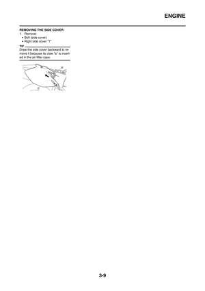 68
68 69
69 70
70 71
71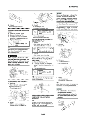 72
72 73
73 74
74 75
75 76
76 77
77 78
78 79
79 80
80 81
81 82
82 83
83 84
84 85
85 86
86 87
87 88
88 89
89 90
90 91
91 92
92 93
93 94
94 95
95 96
96 97
97 98
98 99
99 100
100 101
101 102
102 103
103 104
104 105
105 106
106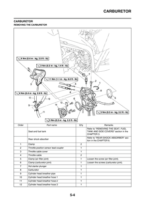 107
107 108
108 109
109 110
110 111
111 112
112 113
113 114
114 115
115 116
116 117
117 118
118 119
119 120
120 121
121 122
122 123
123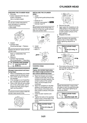 124
124 125
125 126
126 127
127 128
128 129
129 130
130 131
131 132
132 133
133 134
134 135
135 136
136 137
137 138
138 139
139 140
140 141
141 142
142 143
143 144
144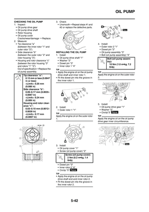 145
145 146
146 147
147 148
148 149
149 150
150 151
151 152
152 153
153 154
154 155
155 156
156 157
157 158
158 159
159 160
160 161
161 162
162 163
163 164
164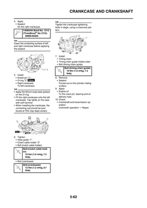 165
165 166
166 167
167 168
168 169
169 170
170 171
171 172
172 173
173 174
174 175
175 176
176 177
177 178
178 179
179 180
180 181
181 182
182 183
183 184
184 185
185 186
186 187
187 188
188 189
189 190
190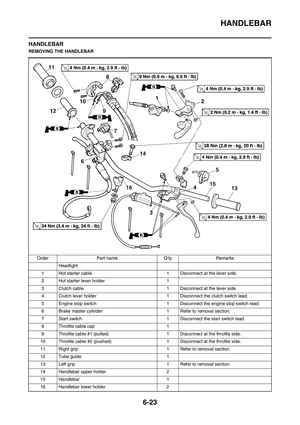 191
191 192
192 193
193 194
194 195
195 196
196 197
197 198
198 199
199 200
200 201
201 202
202 203
203 204
204 205
205 206
206 207
207 208
208 209
209 210
210 211
211 212
212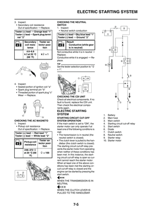 213
213 214
214 215
215 216
216 217
217 218
218 219
219 220
220 221
221 222
222 223
223 224
224 225
225 226
226 227
227 228
228 229
229