Page 65 of 78

Maintenance
58
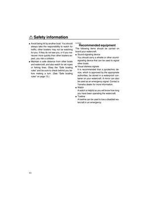
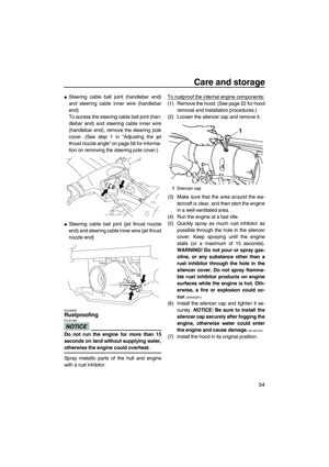
EJU40830Periodic maintenance chart
The periodic maintenance chart gives general guidelines for periodic maintenance. Have a
Yamaha dealer perform the checks in the following chart. However, maintenance may need to
be performed more frequently depending on your operating conditions. If you have any ques-
tions, consult a Yamaha dealer.
This“” mark indicates maintenance that you may do yourself.
This“” mark indicates items to be checked and serviced by a Yamaha dealer.
Item OperationInitial Thereafter every
Page 10
hours50 hours100
hours200
hours
6
months12
months12
months24
months
Spark plugsCheck, clean, replace 59
Lubrication pointsLubricate 53
Intermediate hous-
ingLubricate 59
Fuel systemCheck—
Fuel filterCheck 59
Check, replace—
Fuel tankCheck, clean—
CarburetorCheck, adjust—
Engine idling
speedCheck, adjust 61
Carburetor throt-
tle shaftCheck—
Bilge strainerClean—
ImpellerCheck—
Jet thrust nozzle
angleCheck, adjust—
Handlebar pivot
shaftCheck, adjust—
Steering frictionCheck, adjust—
Throttle cableCheck, adjust—
Choke cableCheck, adjust 60
BatteryCheck, charge—
Rubber couplingCheck—
Engine mountCheck—
UF2F72E0.book Page 58 Friday, May 22, 2009 5:11 PM
Page 66 of 78

Intermediate housing
Fill the intermediate")
Maintenance
59
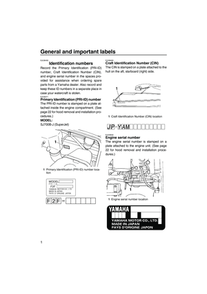
EJU41180Lubrication points
Lubricate moving parts with water-resistant
grease. (See page 53 for information on the
main lubrication points.)
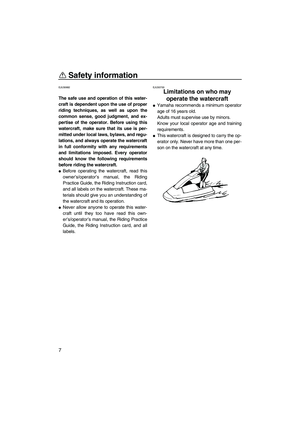
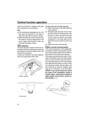
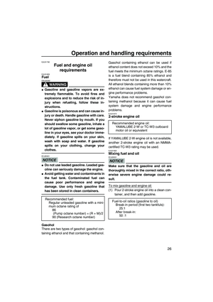
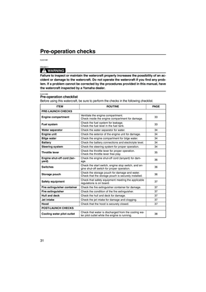
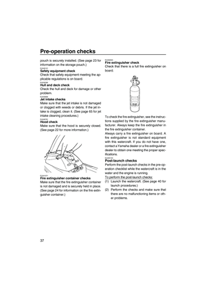
Intermediate housing
Fill the intermediate housing with water-resis-
tant grease through the grease nipple using a
grease gun.
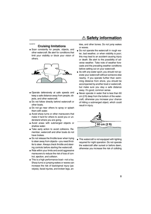
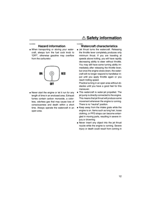
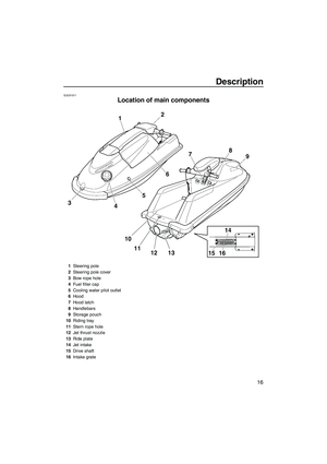
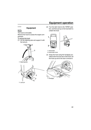
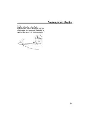
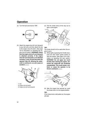
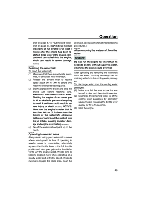
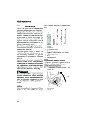
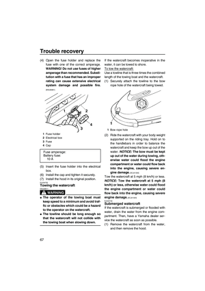
EJU34225Checking the fuel filter
Check the fuel filter. The fuel filter should be
replaced if water or dirt is found in the filter.Have a Yamaha dealer replace the fuel filter if
necessary.
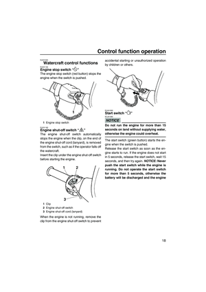
EJU34377Checking the spark plugs
WARNING
EWJ00350
Be careful not to damage the insulator
when removing or installing a spark plug.
A damaged insulator could allow sparks to
escape, which could result in a fire or ex-
plosion.
Remove and check the condition of the spark
plugs.
The condition of a spark plug can indicate
something about the condition of the engine.
For example, if the center electrode portion is
very white, this could indicate an intake air
leak or carburetion problem in that cylinder.
Do not attempt to diagnose any problems
yourself. Have a Yamaha dealer service the
watercraft.
Nuts and boltsCheck— Item OperationInitial Thereafter every
Page 10
hours50 hours100
hours200
hours
6
months12
months12
months24
months
Recommended water-resistant grease:
Yamaha Marine Grease/Yamaha
Grease A
Grease quantity:
Initial 10 hours or 1 month:
20.0–22.0 cm³ (0.68–0.74 US oz,
0.71–0.78 Imp.oz)
Every 100 hours or 12 months:
3.0–5.0 cm³ (0.10–0.17 US oz,
0.11–0.18 Imp.oz)
1Fuel filter
UF2F72E0.book Page 59 Friday, May 22, 2009 5:11 PM
Page 67 of 78
 Remove the hood. (See page 22 for hood
removal and installation procedures.)
(2) Remove the spark plug cap.
(3) Remove the spark plug, and then check
the con")
Maintenance
60
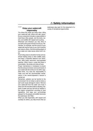
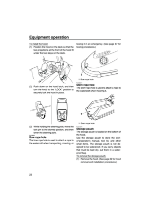
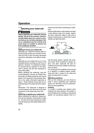
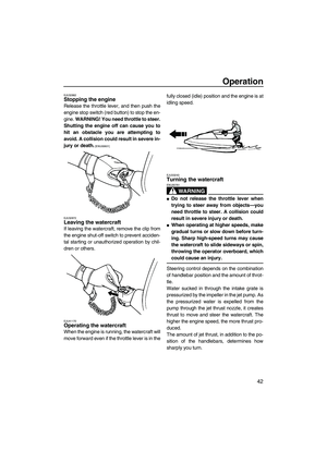
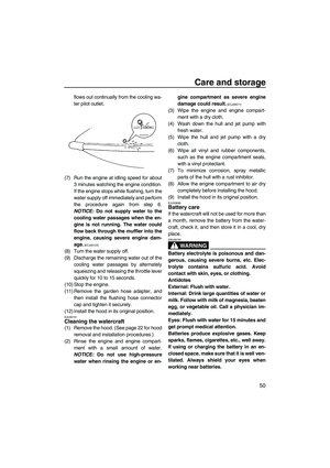
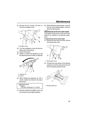
To remove a spark plug:
(1) Remove the hood. (See page 22 for hood
removal and installation procedures.)
(2) Remove the spark plug cap.
(3) Remove the spark plug, and then check
the condition of the spark plug and the
spark plug gap. If the electrode portion is
significantly discolored, if electrode ero-
sion becomes excessive, if carbon and
other deposits are excessive, or if the
spark plug gap is not within the specified
range, replace the spark plug.
TIP:
When the engine is operating normally, the
color of the spark plug electrode portion will
be a medium-to-light tan.
To install a spark plug:
(1) Wipe off any dirt from the threads, insula-
tor, and gasket surface of the spark plug.
(2) Install the spark plug, and then tighten it
to the specified torque.
TIP:
If a torque wrench is not available when you
are installing a spark plug, a good estimate of
the correct torque is 1/4 turn to 1/2 turn past
finger tight using the spark plug wrench in-
cluded in the tool kit. Have the spark plug ad-
justed to the correct torque with a torque
wrench as soon as possible.
(3) Wipe off any water or dirt inside the spark
plug cap.
(4) Install the spark plug cap by pushing it
down until it is securely installed in its
original position.
(5) Install the hood in its original position.
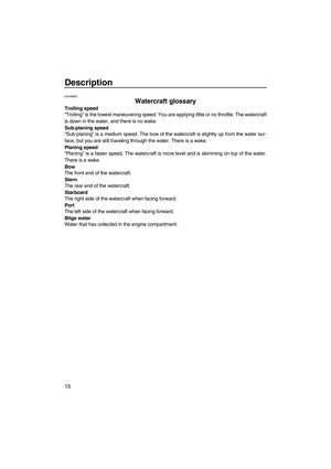
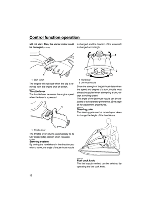
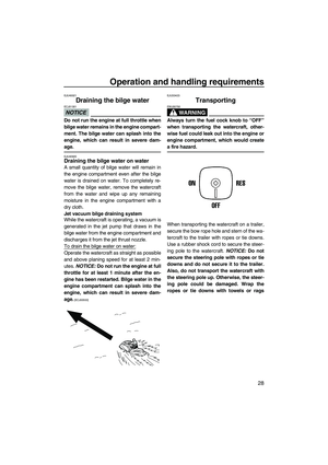
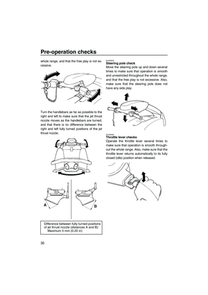
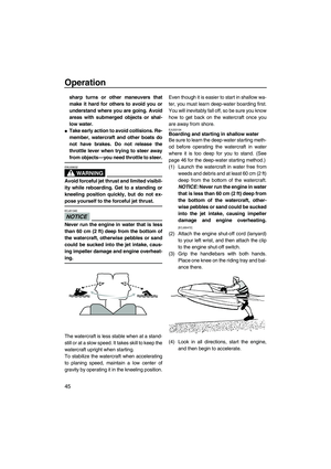
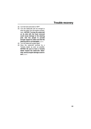
EJU34441Adjusting the choke cable
Check that the choke cable is properly adjust-
ed.
To adjust the choke cable:
(1) Pull the choke knob out until it stops, and
then release the knob. The knob should
not move.
(2) If the choke knob moves back on its own,
tighten the choke knob adjusting nut
slightly. If the knob is difficult to move,
loosen the adjusting nut slightly.
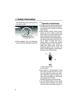
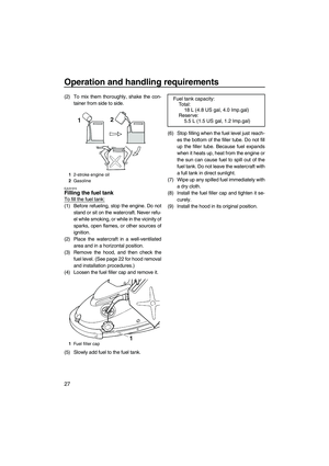
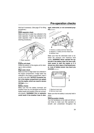
1Insulator
2Electrode
3Spark plug gap
Specified spark plug:
BR7HS
Spark plug gap:
0.6–0.7 mm (0.024–0.028 in)
Tightening torque:
Spark plug:
25.0 Nm (2.55 kgf-m, 18.4 ft-lb)
1Choke knob adjusting nut
UF2F72E0.book Page 60 Friday, May 22, 2009 5:11 PM
Page 68 of 78

Maintenance
61
EJU34463Adjusting the carburetor
NOTICE
ECJ00172
If the carburetor settings are disturbed by
someone who does not have the neces-
sary technical knowledge, poor engine
performance and damage may result.
The carburetor is a vital part of the engine and
requires very sophisticated adjustments.
Most adjustments should be left to a Yamaha
dealer who has the professional knowledge
and experience to make them.
However, the operator may adjust the engine
idling speed as part of the usual maintenance
routine.
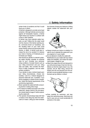
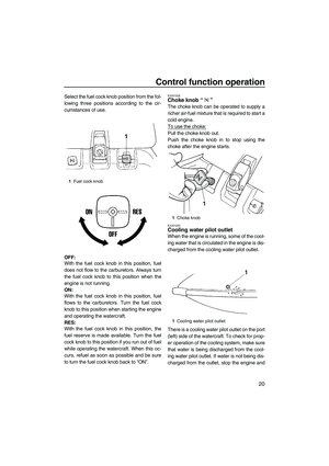
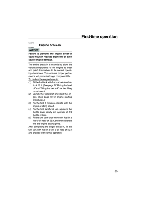
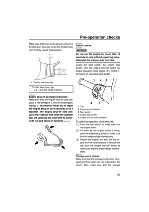
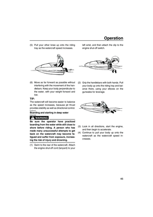
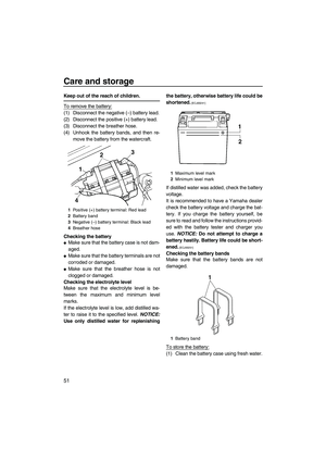
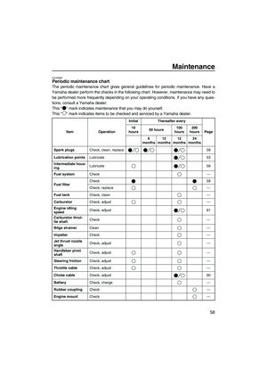
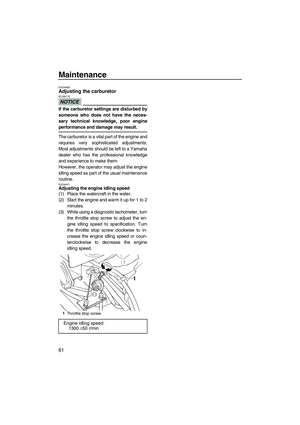
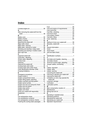
EJU34471Adjusting the engine idling speed
(1) Place the watercraft in the water.
(2) Start the engine and warm it up for 1 to 2
minutes.
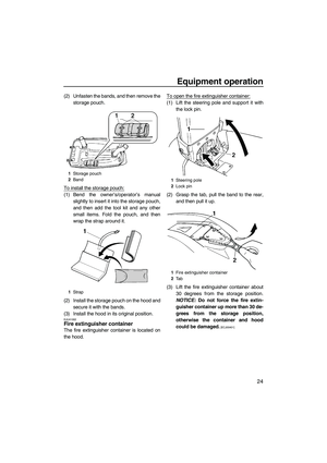
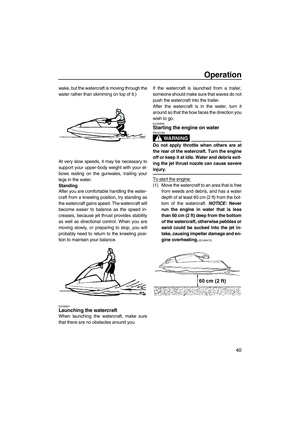
(3) While using a diagnostic tachometer, turn
the throttle stop screw to adjust the en-
gine idling speed to specification. Turn
the throttle stop screw clockwise to in-
crease the engine idling speed or coun-
terclockwise to decrease the engine
idling speed.
1Throttle stop screw
Engine idling speed:
1300 ±50 r/min
UF2F72E0.book Page 61 Friday, May 22, 2009 5:11 PM
Page 69 of 78

Width:
680 mm (26.8 in)
Height:
660 mm (26.0 in)
Dry weight:
139")
Specifications
62
EJU34542
Specifications
Watercraft capacity:
Maximum people on board:
1 person
Dimensions:
Length:
2240 mm (88.2 in)
Width:
680 mm (26.8 in)
Height:
660 mm (26.0 in)
Dry weight:
139 kg (306 lb)
Performance:
Maximum output (according to ISO 8665/SAE
J1228):
48.50 kW@6250 r/min
Maximum fuel consumption:
29.0 L/h (7.7 US gal/h, 6.4 Imp.gal/h)
Cruising range at full throttle:
0.62 hour
Trolling speed:
1300 ±50 r/min
Engine:
Engine type:
2-stroke
Number of cylinders:
2
Engine displacement:
701 cm³
Bore & stroke:
81.0 × 68.0 mm (3.19 × 2.68 in)
Compression ratio:
7.2 : 1
Lubrication system:
Pre-mixed fuel and oil
Cooling system:
Water
Starting system:
Electric
Ignition system:
C.D.I.
Spark plug:
BR7HS
Spark plug gap:
0.6–0.7 mm (0.024–0.028 in)
Battery capacity:
12 V, 19.0 AhCharging system:
Flywheel magneto
Drive unit:
Propulsion system:
Jet pump
Jet pump type:
Axial flow, single stage
Impeller rotation:
Counterclockwise
Jet thrust nozzle angle:
P1: 14.4+14.4°
P2: 17.3+17.3°
Fuel and oil:
Recommended fuel:
Regular unleaded gasoline
Minimum octane rating (PON):
86
Minimum octane rating (RON):
90
Recommended engine oil:
YAMALUBE 2-W or TC-W3 outboard motor
oil or equivalent
Fuel mixing ratio (fuel to oil):
50 :1
Fuel tank total capacity:
18 L (4.8 US gal, 4.0 Imp.gal)
Fuel tank reserve capacity:
5.5 L (1.5 US gal, 1.2 Imp.gal)
UF2F72E0.book Page 62 Friday, May 22, 2009 5:11 PM
Page 70 of 78

Trouble recovery
63
EJU34561
Troubleshooting
If you have any trouble with your watercraft, use the troubleshooting chart to check for the pos-
sible cause.
If you cannot find the cause, consult a Yamaha dealer.
EJU34574Troubleshooting chart
TROUBLE POSSIBLE CAUSE REMEDY PAGE
Engine does not
start (Starter motor
does not turn over)Engine shut-
off switchClip not in place Install clip
18
Fuse Burned out Replace fuse and
check wiring66
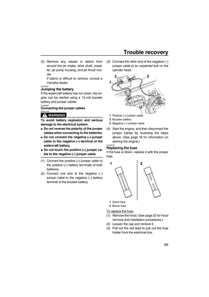
Battery Run down Recharge 50
Poor terminal con-
nectionsTighten as required
50
Terminal corroded Clean or replace 50
Starter motor Faulty Have serviced by
Yamaha dealer—
Engine does not
start (Starter motor
turns over)Fuel cock Turned to “OFF”Turn fuel cock knob to
“ON”19
Fuel Empty Refill as soon as pos-
sible27
Stale or contaminat-
edHave serviced by
Yamaha dealer—
Fuel tank Water or dirt present Have serviced by
Yamaha dealer—
Spark plug Fouled or defective Replace 59
Spark plug
capNot connected or
looseConnect properly
59
Crankcase Filled with water Have serviced by
Yamaha dealer67
Fuel filter Clogged or water
pooledHave serviced by
Yamaha dealer59
Choke Knob moves back on
its ownTighten choke knob
adjusting nut60
UF2F72E0.book Page 63 Friday, May 22, 2009 5:11 PM
Page 71 of 78

Trouble recovery
64
Engine runs irregu-
larly or stallsFuel Empty Refill as soon as pos-
sible27
Stale or contaminat-
edHave serviced by
Yamaha dealer—
Too much oil in fuel
mixing ratioCorrect fuel-to-oil ra-
tio to 50:126
Choke Knob is left pulled Push fully in 20
Fuel filter Clogged or water
pooledHave serviced by
Yamaha dealer59
Fuel tank Water or dirt present Have serviced by
Yamaha dealer—
Spark plug Fouled or defective Replace 59
Incorrect heat range Replace 59
Gap incorrect Replace 59
Spark plug
capLoose Connect properly 59
Cracked, torn or dam-
agedHave serviced by
Yamaha dealer—
Electrical wir-
ingLoose electrical con-
nectionsHave serviced by
Yamaha dealer—
Carburetor Incorrect idle adjust-
mentHave serviced by
Yamaha dealer—
Clogged Have serviced by
Yamaha dealer61
Watercraft slow or
loses powerCavitation Jet intake clogged Clean 65
Impeller damaged or
wornHave serviced by
Yamaha dealer65
Engine over-
heatedJet intake clogged Clean
65
Fuel filter Clogged Have serviced by
Yamaha dealer59
Spark plug Fouled or defective Replace 59
Incorrect heat range Replace 59
Gap incorrect Replace 59
Spark plug
capsLoose Connect properly
59
Fuel Stale or contaminat-
edHave serviced by
Yamaha dealer— TROUBLE POSSIBLE CAUSE REMEDY PAGE
UF2F72E0.book Page 64 Friday, May 22, 2009 5:11 PM
Page 72 of 78

Trouble recovery
65
EJU34622
Emergency procedures EJU34634Cleaning the jet intake and impeller
WARNING
EWJ00782
Before attempting to remove weeds or de-
bris from the jet intake or impeller area,
shut the engine off and remove the clip
from the engine shut-off switch. Severe in-
jury or death could result from coming in
contact with the rotating parts of the jet
pump.
If weeds or debris gets caught in the jet intake
or impeller, cavitation can occur, causing jet
thrust to decrease even though engine speed
rises. If this condition is allowed to continue,
the engine will overheat and may seize.
NOTICE: If weeds or debris gets caught in
the jet intake, do not operate the watercraft
above trolling speed until they have been
removed.
[ECJ00653]
If there is any sign that the jet intake or impel-
ler is clogged with weeds or debris, return to
shore and check the intake and impeller. Al-ways stop the engine before beaching the wa-
tercraft.
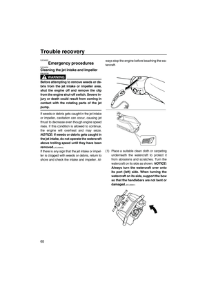
(1) Place a suitable clean cloth or carpeting
underneath the watercraft to protect it
from abrasions and scratches. Turn the
watercraft on its side as shown. NOTICE:
Always turn the watercraft over onto
its port (left) side. When turning the
watercraft on its side, support the bow
so that the handlebars are not bent or
damaged.
[ECJ00661]
UF2F72E0.book Page 65 Friday, May 22, 2009 5:11 PM