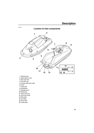
Page 25 of 78
 stops the
engine when the switch is pushed.
EJU31163Engine shu")
Control function operation
18
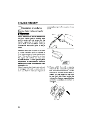
EJU31024
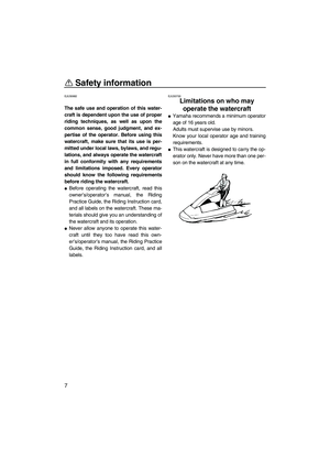
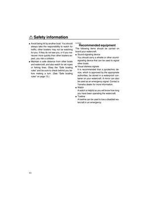
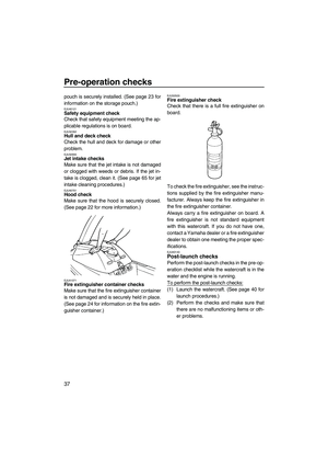
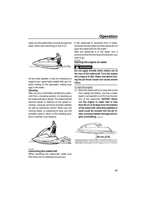
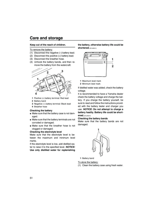
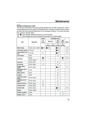
Watercraft control functions EJU31152Engine stop switch“”
The engine stop switch (red button) stops the
engine when the switch is pushed.
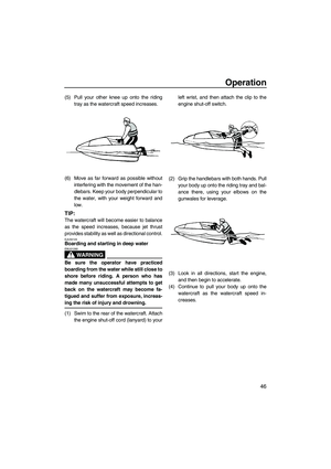
EJU31163Engine shut-off switch“”
The engine shut-off switch automatically
stops the engine when the clip, on the end of
the engine shut-off cord (lanyard), is removed
from the switch, such as if the operator falls off
the watercraft.
Insert the clip under the engine shut-off switch
before starting the engine.
When the engine is not running, remove the
clip from the engine shut-off switch to preventaccidental starting or unauthorized operation
by children or others.
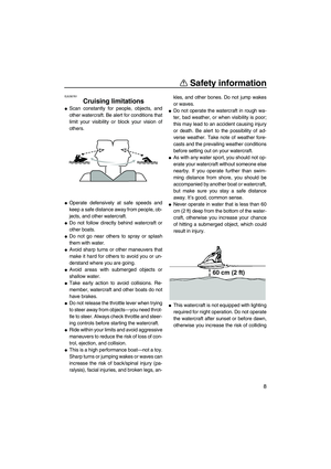
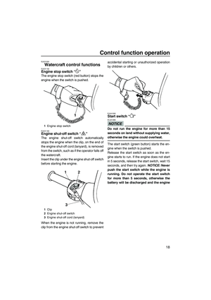
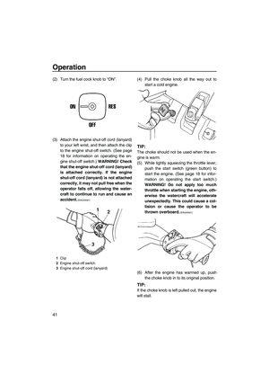
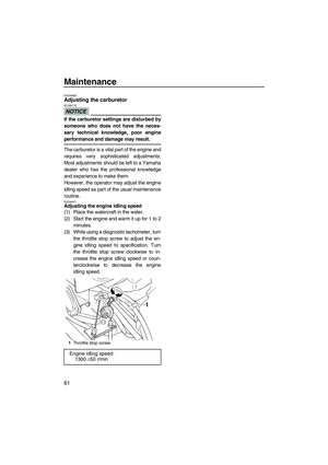
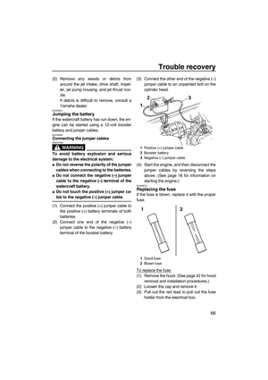
EJU41050Start switch“”
NOTICE
ECJ01360
Do not run the engine for more than 15
seconds on land without supplying water,
otherwise the engine could overheat.
The start switch (green button) starts the en-
gine when the switch is pushed.
Release the start switch as soon as the en-
gine starts to run. If the engine does not start
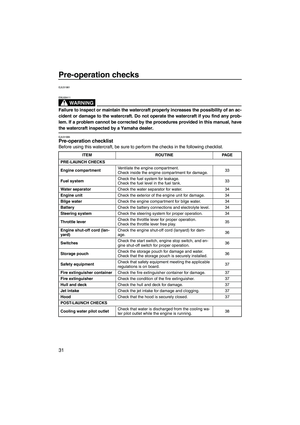
in 5 seconds, release the start switch, wait 15
seconds, and then try again. NOTICE: Never
push the start switch while the engine is
running. Do not operate the start switch
for more than 5 seconds, otherwise the
battery will be discharged and the engine
1Engine stop switch
1Clip
2Engine shut-off switch
3Engine shut-off cord (lanyard)
UF2F72E0.book Page 18 Friday, May 22, 2009 5:11 PM
Page 26 of 78
![YAMAHA SUPERJET 2010 Owners Manual Control function operation
19
will not start. Also, the starter motor could
be damaged.
[ECJ01040]
The engine will not start when the clip is re-
moved from the engine shut-off switch.
EJU31211Thrott](/manual-img/51/51304/w960_51304-25.png "YAMAHA SUPERJET 2010 Owners Manual Control function operation
19
will not start. Also, the starter motor could
be damaged.
[ECJ01040]
The engine will not start when the clip is re-
moved from the engine shut-off switch.
EJU31211Thrott")
Control function operation
19
will not start. Also, the starter motor could
be damaged.
[ECJ01040]
The engine will not start when the clip is re-
moved from the engine shut-off switch.
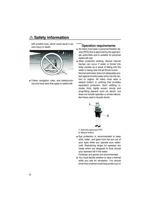
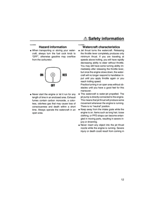
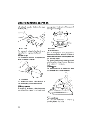
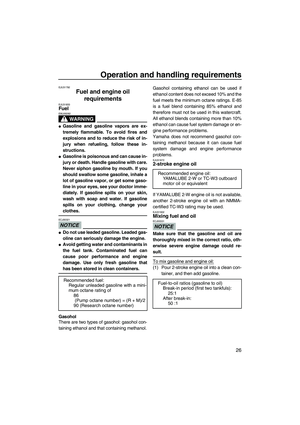
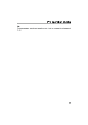
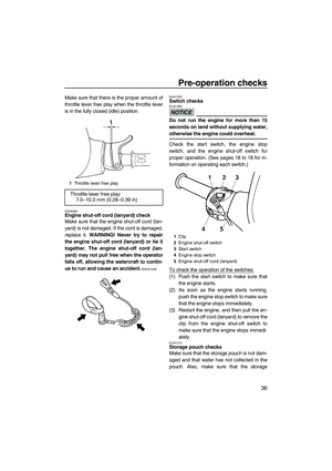
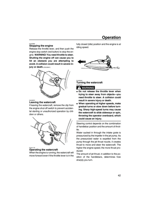
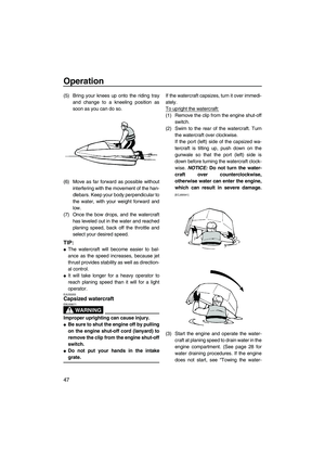
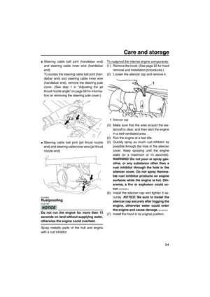
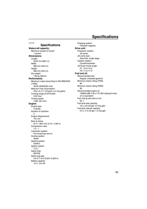
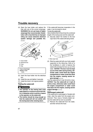
EJU31211Throttle lever
The throttle lever increases the engine speed
when the lever is squeezed.
The throttle lever returns automatically to its
fully closed (idle) position when released.
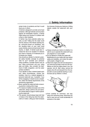
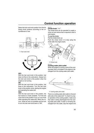
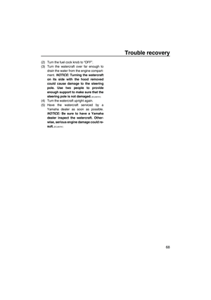
EJU35931Steering system
By turning the handlebars in the direction you
wish to travel, the angle of the jet thrust nozzleis changed, and the direction of the watercraft
is changed accordingly.
Since the strength of the jet thrust determines
the speed and degree of a turn, throttle must
always be applied when attempting a turn, ex-
cept at trolling speed.
The angle of the jet thrust nozzle can be ad-
justed to suit operator preference. (See page
56 for adjustment procedures.)
EJU31272Steering pole
The steering pole can be moved up or down
to change the height of the handlebars.
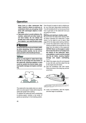
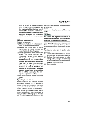
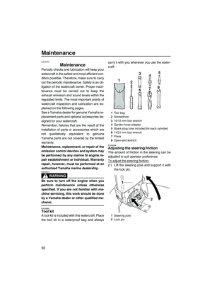
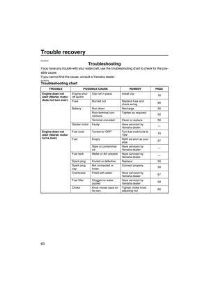
EJU31123Fuel cock knob
The fuel supply method can be switched by
operating the fuel cock knob.
1Start switch
1Throttle lever1Handlebar
2Jet thrust nozzle
UF2F72E0.book Page 19 Friday, May 22, 2009 5:11 PM
Page 27 of 78

Control function operation
20
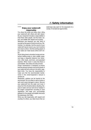
Select the fuel cock knob position from the fol-
lowing three positions according to the cir-
cumstances of use.
OFF:
With the fuel cock knob in this position, fuel
does not flow to the carburetors. Always turn
the fuel cock knob to this position when the
engine is not running.
ON:
With the fuel cock knob in this position, fuel
flows to the carburetors. Turn the fuel cock
knob to this position when starting the engine
and operating the watercraft.
RES:
With the fuel cock knob in this position, the
fuel reserve is made available. Turn the fuel
cock knob to this position if you run out of fuel
while operating the watercraft. When this oc-
curs, refuel as soon as possible and be sure
to turn the fuel cock knob back to “ON”.EJU31202Choke knob“”
The choke knob can be operated to supply a
richer air-fuel mixture that is required to start a
cold engine.
To use the choke:
Pull the choke knob out.
Push the choke knob in to stop using the
choke after the engine starts.
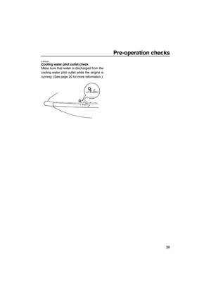
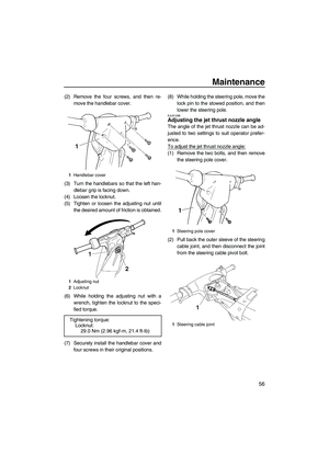
EJU31222Cooling water pilot outlet
When the engine is running, some of the cool-
ing water that is circulated in the engine is dis-
charged from the cooling water pilot outlet.
There is a cooling water pilot outlet on the port
(left) side of the watercraft. To check for prop-
er operation of the cooling system, make sure
that water is being discharged from the cool-
ing water pilot outlet. If water is not being dis-
charged from the outlet, stop the engine and
1Fuel cock knob
1Choke knob
1Cooling water pilot outlet
UF2F72E0.book Page 20 Friday, May 22, 2009 5:11 PM
Page 28 of 78

TIP:
�If the cooling water passages are dry, it will
take about 20 seconds for the wat")
Control function operation
21
check the jet intake for clogging. (See page
65 for information on the jet intake.)
TIP:
�If the cooling water passages are dry, it will
take about 20 seconds for the water to
reach the outlet after the engine is started.
�Water discharge may not be constant when
the engine is running at idling speed. If this
occurs, apply a little throttle to make sure
that water discharges properly.
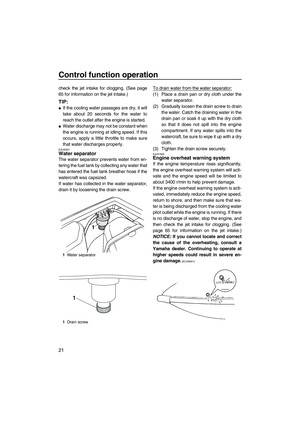
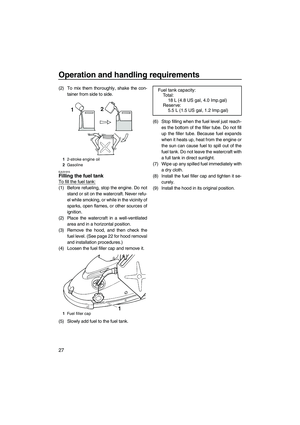
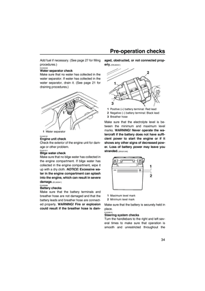
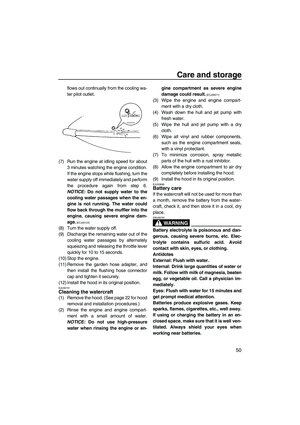
EJU40321Water separator
The water separator prevents water from en-
tering the fuel tank by collecting any water that
has entered the fuel tank breather hose if the
watercraft was capsized.
If water has collected in the water separator,
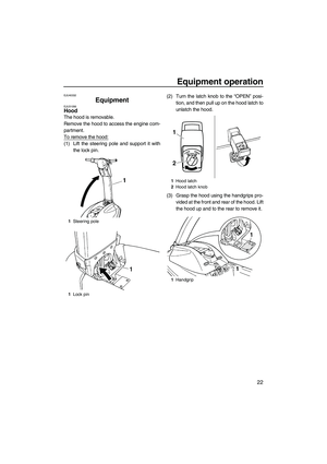
drain it by loosening the drain screw.To drain water from the water separator:
(1) Place a drain pan or dry cloth under the
water separator.
(2) Gradually loosen the drain screw to drain
the water. Catch the draining water in the
drain pan or soak it up with the dry cloth
so that it does not spill into the engine
compartment. If any water spills into the
watercraft, be sure to wipe it up with a dry
cloth.
(3) Tighten the drain screw securely.
EJU31664Engine overheat warning system
If the engine temperature rises significantly,
the engine overheat warning system will acti-
vate and the engine speed will be limited to
about 3400 r/min to help prevent damage.
If the engine overheat warning system is acti-
vated, immediately reduce the engine speed,
return to shore, and then make sure that wa-
ter is being discharged from the cooling water
pilot outlet while the engine is running. If there
is no discharge of water, stop the engine, and
then check the jet intake for clogging. (See
page 65 for information on the jet intake.)
NOTICE: If you cannot locate and correct
the cause of the overheating, consult a
Yamaha dealer. Continuing to operate at
higher speeds could result in severe en-
gine damage.
[ECJ00041]
1Water separator
1Drain screw
1
UF2F72E0.book Page 21 Friday, May 22, 2009 5:11 PM
Page 29 of 78
Equipment operation
22
EJU40332
Equipment EJU31056Hood
The hood is removable.
Remove the hood to access the engine com-
partment.
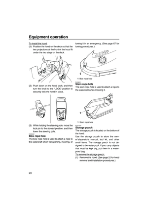
To remove the hood:
(1) Lift the steering pole and support it with
the lock pin.(2) Turn the latch knob to the “OPEN” posi-
tion, and then pull up on the hood latch to
unlatch the hood.
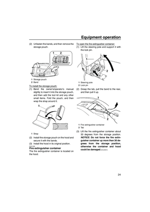
(3) Grasp the hood using the handgrips pro-
vided at the front and rear of the hood. Lift
the hood up and to the rear to remove it.
1Steering pole
1Lock pin
1Hood latch
2Hood latch knob
1Handgrip
LOCKOPEN
1
2
UF2F72E0.book Page 22 Friday, May 22, 2009 5:11 PM
Page 30 of 78
 Position the hood on the deck so that the
two projections at the front of the hood fit
under the two stays on the deck.
(2) Push down on the hood latch,")
Equipment operation
23
To install the hood:
(1) Position the hood on the deck so that the
two projections at the front of the hood fit
under the two stays on the deck.
(2) Push down on the hood latch, and then
turn the knob to the “LOCK” position to
securely lock the hood in place.
(3) While holding the steering pole, move the
lock pin to the stowed position, and then
lower the steering pole.
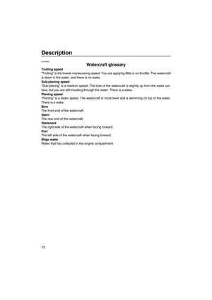
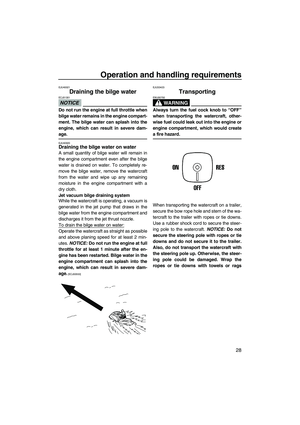
EJU36001Bow rope hole
The bow rope hole is used to attach a rope to
the watercraft when transporting, mooring, ortowing it in an emergency. (See page 67 for
towing procedures.)
EJU36011Stern rope hole
The stern rope hole is used to attach a rope to
the watercraft when mooring it.
EJU31674Storage pouch
The storage pouch is located on the bottom of
the hood.
Use the storage pouch to store the own-
er’s/operator’s manual, tool kit, and other
small items. The storage pouch is not de-
signed to be waterproof. If you carry objects
that must be kept dry, put them in a water-
proof bag.
To remove the storage pouch:
(1) Remove the hood. (See page 22 for hood
removal and installation procedures.)
LOCKOPEN
1Bow rope hole
1Stern rope hole
UF2F72E0.book Page 23 Friday, May 22, 2009 5:11 PM
Page 31 of 78
 Unfasten the bands, and then remove the
storage pouch.
To install the storage pouch:
(1) Bend the owner’s/operator’s manual
slightly to insert it into the storage pouch,")
Equipment operation
24
(2) Unfasten the bands, and then remove the
storage pouch.
To install the storage pouch:
(1) Bend the owner’s/operator’s manual
slightly to insert it into the storage pouch,
and then add the tool kit and any other
small items. Fold the pouch, and then
wrap the strap around it.
(2) Install the storage pouch on the hood and
secure it with the bands.
(3) Install the hood in its original position.
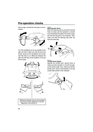
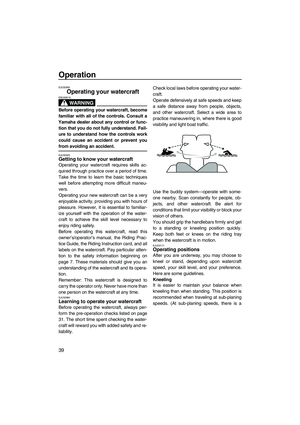
EJU41002Fire extinguisher container
The fire extinguisher container is located on
the hood.To open the fire extinguisher container:
(1) Lift the steering pole and support it with
the lock pin.
(2) Grasp the tab, pull the band to the rear,
and then pull it up.
(3) Lift the fire extinguisher container about
30 degrees from the storage position.
NOTICE: Do not force the fire extin-
guisher container up more than 30 de-
grees from the storage position,
otherwise the container and hood
could be damaged.
[ECJ00401]
1Storage pouch
2Band
1Strap
1Steering pole
2Lock pin
1Fire extinguisher container
2Ta b
UF2F72E0.book Page 24 Friday, May 22, 2009 5:11 PM
Page 32 of 78
Equipment operation
25
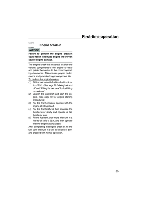
(4) Loosen the fire extinguisher container
cap and remove it.
To close the fire extinguisher container:
(1) Insert the fire extinguisher into the con-
tainer, and then install the fire extinguish-
er container cap and tighten it securely.
(2) Lower the container on the hood to its
storage position and secure it with the
band.
(3) While holding the steering pole, move the
lock pin to the stowed position, and then
lower the steering pole.
1Fire extinguisher container cap
UF2F72E0.book Page 25 Friday, May 22, 2009 5:11 PM


 Lift the steering pole and support it with
th")
 Loosen the fire extinguisher container
cap and remove it.
To close the fire extinguisher container:
(1) Insert the fire extinguisher into the con-
tainer, and then install t")