Page 57 of 78
 Run the engine at idling speed for about
3 minutes watching the engine condition.
If the engine stops while flushin")
Care and storage
50
flows out continually from the cooling wa-
ter pilot outlet.
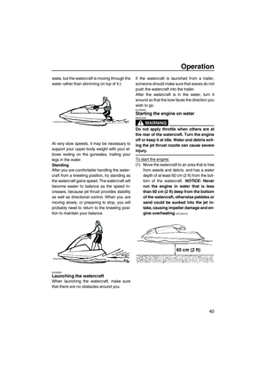
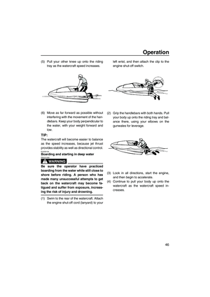
(7) Run the engine at idling speed for about
3 minutes watching the engine condition.
If the engine stops while flushing, turn the
water supply off immediately and perform
the procedure again from step 6.
NOTICE: Do not supply water to the
cooling water passages when the en-
gine is not running. The water could
flow back through the muffler into the
engine, causing severe engine dam-
age.
[ECJ00122]
(8) Turn the water supply off.
(9) Discharge the remaining water out of the
cooling water passages by alternately
squeezing and releasing the throttle lever
quickly for 10 to 15 seconds.
(10) Stop the engine.
(11) Remove the garden hose adapter, and
then install the flushing hose connector
cap and tighten it securely.
(12) Install the hood in its original position.
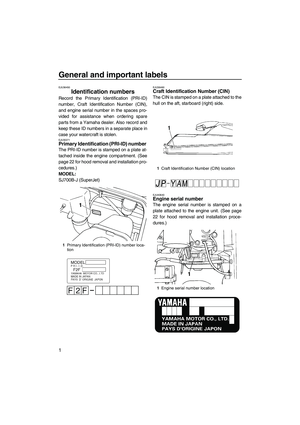
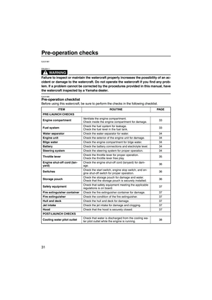
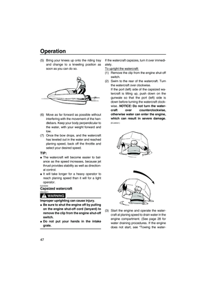
EJU40741Cleaning the watercraft
(1) Remove the hood. (See page 22 for hood
removal and installation procedures.)
(2) Rinse the engine and engine compart-
ment with a small amount of water.
NOTICE: Do not use high-pressure
water when rinsing the engine or en-gine compartment as severe engine
damage could result.
[ECJ00571]
(3) Wipe the engine and engine compart-
ment with a dry cloth.
(4) Wash down the hull and jet pump with
fresh water.
(5) Wipe the hull and jet pump with a dry
cloth.
(6) Wipe all vinyl and rubber components,
such as the engine compartment seals,
with a vinyl protectant.
(7) To minimize corrosion, spray metallic
parts of the hull with a rust inhibitor.
(8) Allow the engine compartment to air dry
completely before installing the hood.
(9) Install the hood in its original position.
EJU33685Battery care
If the watercraft will not be used for more than
a month, remove the battery from the water-
craft, check it, and then store it in a cool, dry
place.
WARNING
EWJ00791
Battery electrolyte is poisonous and dan-
gerous, causing severe burns, etc. Elec-
trolyte contains sulfuric acid. Avoid
contact with skin, eyes, or clothing.
Antidotes
External: Flush with water.
Internal: Drink large quantities of water or
milk. Follow with milk of magnesia, beaten
egg, or vegetable oil. Call a physician im-
mediately.
Eyes: Flush with water for 15 minutes and
get prompt medical attention.
Batteries produce explosive gases. Keep
sparks, flames, cigarettes, etc., well away.
If using or charging the battery in an en-
closed space, make sure that it is well ven-
tilated. Always shield your eyes when
working near batteries.
UF2F72E0.book Page 50 Friday, May 22, 2009 5:11 PM
Page 58 of 78
 Disconnect the negative (–) battery lead.
(2) Disconnect the positive (+) battery lead.
(3) Disconnect the breather")
Care and storage
51
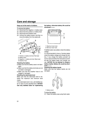
Keep out of the reach of children.
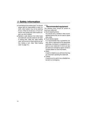
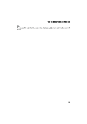
To remove the battery:
(1) Disconnect the negative (–) battery lead.
(2) Disconnect the positive (+) battery lead.
(3) Disconnect the breather hose.
(4) Unhook the battery bands, and then re-
move the battery from the watercraft.
Checking the battery
�Make sure that the battery case is not dam-
aged.
�Make sure that the battery terminals are not
corroded or damaged.
�Make sure that the breather hose is not
clogged or damaged.
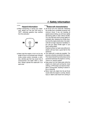
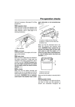
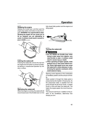
Checking the electrolyte level
Make sure that the electrolyte level is be-
tween the maximum and minimum level
marks.
If the electrolyte level is low, add distilled wa-
ter to raise it to the specified level. NOTICE:
Use only distilled water for replenishingthe battery, otherwise battery life could be
shortened.
[ECJ00241]
If distilled water was added, check the battery
voltage.
It is recommended to have a Yamaha dealer
check the battery voltage and charge the bat-
tery. If you charge the battery yourself, be
sure to read and follow the instructions provid-
ed with the battery tester and charger you
use. NOTICE: Do not attempt to charge a
battery hastily. Battery life could be short-
ened.
[ECJ00251]
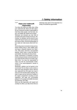
Checking the battery bands
Make sure that the battery bands are not
damaged.
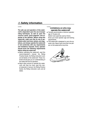
To store the battery:
(1) Clean the battery case using fresh water.
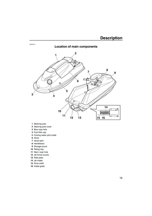
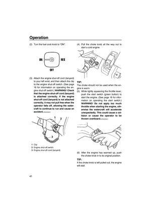
1Positive (+) battery terminal: Red lead
2Battery band
3Negative (–) battery terminal: Black lead
4Breather hose
1Maximum level mark
2Minimum level mark
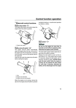
1Battery band
UF2F72E0.book Page 51 Friday, May 22, 2009 5:11 PM
Page 59 of 78
 If the battery terminals are dirty or corrod-
ed, clean them using a wire brush.
(3) Apply Yamaha Marine Grease or
Yamaha Grease A to the battery termi-
nals.
(4) Store the bat")
Care and storage
52
(2) If the battery terminals are dirty or corrod-
ed, clean them using a wire brush.
(3) Apply Yamaha Marine Grease or
Yamaha Grease A to the battery termi-
nals.
(4) Store the battery in a cool, dry place.
NOTICE: Always keep the battery
charged. Storing a discharged battery
can cause permanent battery damage.
[ECJ00101]
To install the battery:
(1) Place the battery in the battery compart-
ment and hook the battery bands onto the
holders.
(2) Connect the positive (+) battery lead (red)
to the positive (+) battery terminal.
NOTICE: Reversal of the battery leads
will damage the electrical parts.
[ECJ00261]
(3) Connect the negative (–) battery lead
(black) to the negative (–) battery termi-
nal.
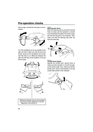
(4) Connect the breather hose to the battery.
WARNING! Fire or explosion could re-
sult if the breather hose is damaged,
obstructed, or not connected proper-
ly.
[EWJ00451]
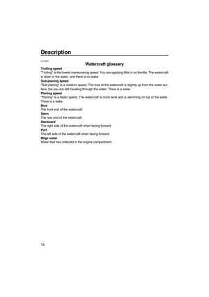
(5) Make sure that the battery is securely
held in place.
1Battery terminal
Recommended water-resistant grease:
Yamaha Marine Grease/Yamaha
Grease A
UF2F72E0.book Page 52 Friday, May 22, 2009 5:11 PM
Page 60 of 78

Care and storage
53
EJU33483
Long-term storage
WARNING
EWJ00320
Always turn the fuel cock knob to “OFF”
when storing the watercraft, otherwise
fuel could leak out into the engine or en-
gine compartment, which would create a
fire hazard.
Storage for long periods of time, such as win-
ter storage, requires preventive maintenance
to ensure against deterioration. It is advisable
to have the watercraft serviced by a Yamaha
dealer prior to storage.
However, the following procedures can be
performed easily by the owner.
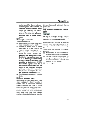
EJU40761Cleaning
(1) Flush the cooling water passages. (See
page 49 for flushing procedures.)
TIP:
If you will be storing the watercraft for a pro-
longed period, such as winter storage, top off
the fuel tank with fresh gasoline and add fuel
stabilizer and conditioner to the fuel tank ac-
cording to the manufacturer's instruction be-
fore starting the engine.
(2) Clean the watercraft. (See page 50 for
watercraft cleaning procedures.)
Wax the hull with a non-abrasive wax.
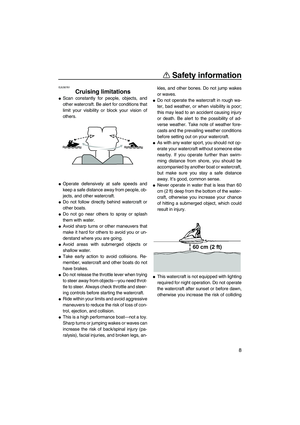
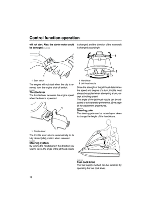
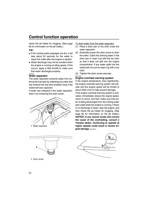
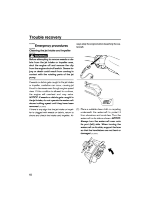
EJU40793Lubrication
Use a suitable marine grease applicator and
spray a rust inhibitor between the inner and
outer cables to lubricate the cables and purge
out any dirt and moisture.
To keep moving parts sliding or rotating
smoothly, lubricate them with water-resistant
grease.
�Throttle cable (carburetor end) and choke
cable (carburetor end)
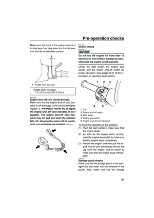
�Throttle cable (throttle lever end)
Squeeze the throttle lever and remove the
seal. Spray a rust inhibitor into the outer ca-
ble. Refit the seal securely.
Recommended water-resistant grease:
Yamaha Marine Grease/Yamaha
Grease A
1Seal
UF2F72E0.book Page 53 Friday, May 22, 2009 5:11 PM
Page 61 of 78

and steering cable inner wire (handlebar
end)
To access the steering cable ball joint (han-
dlebar end) and steering cable inner wire
(ha")
Care and storage
54
�Steering cable ball joint (handlebar end)
and steering cable inner wire (handlebar
end)
To access the steering cable ball joint (han-
dlebar end) and steering cable inner wire
(handlebar end), remove the steering pole
cover. (See step 1 in “Adjusting the jet
thrust nozzle angle” on page 56 for informa-
tion on removing the steering pole cover.)
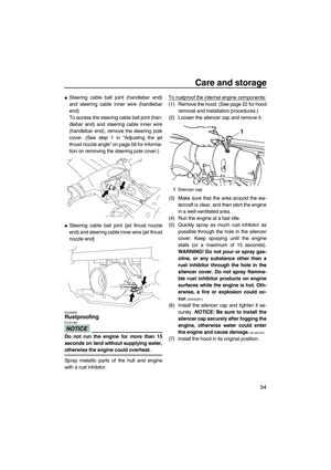
�Steering cable ball joint (jet thrust nozzle
end) and steering cable inner wire (jet thrust
nozzle end)
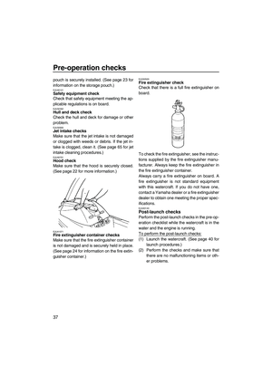
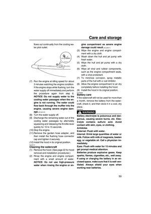
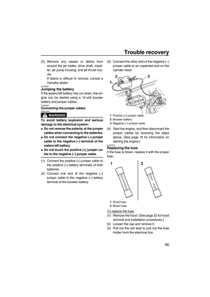
EJU40942Rustproofing
NOTICE
ECJ01360
Do not run the engine for more than 15
seconds on land without supplying water,
otherwise the engine could overheat.
Spray metallic parts of the hull and engine
with a rust inhibitor.To rustproof the internal engine components:
(1) Remove the hood. (See page 22 for hood
removal and installation procedures.)
(2) Loosen the silencer cap and remove it.
(3) Make sure that the area around the wa-
tercraft is clear, and then start the engine
in a well-ventilated area.
(4) Run the engine at a fast idle.
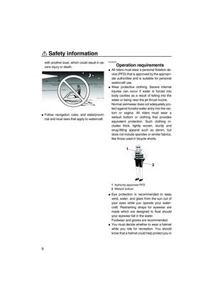
(5) Quickly spray as much rust inhibitor as
possible through the hole in the silencer
cover. Keep spraying until the engine
stalls (or a maximum of 15 seconds).
WARNING! Do not pour or spray gas-
oline, or any substance other than a
rust inhibitor through the hole in the
silencer cover. Do not spray flamma-
ble rust inhibitor products on engine
surfaces while the engine is hot. Oth-
erwise, a fire or explosion could oc-
cur.
[EWJ00301]
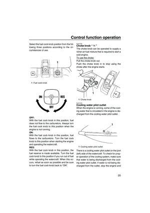
(6) Install the silencer cap and tighten it se-
curely. NOTICE: Be sure to install the
silencer cap securely after fogging the
engine, otherwise water could enter
the engine and cause damage.
[ECJ00152]
(7) Install the hood in its original position.
1Silencer cap
UF2F72E0.book Page 54 Friday, May 22, 2009 5:11 PM
Page 62 of 78

Maintenance
55
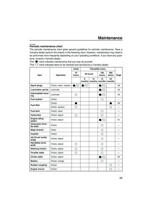
EJU33767
Maintenance
Periodic checks and lubrication will keep your
watercraft in the safest and most efficient con-
dition possible. Therefore, make sure to carry
out the periodic maintenance. Safety is an ob-
ligation of the watercraft owner. Proper main-
tenance must be carried out to keep the
exhaust emission and sound levels within the
regulated limits. The most important points of
watercraft inspection and lubrication are ex-
plained on the following pages.
See a Yamaha dealer for genuine Yamaha re-
placement parts and optional accessories de-
signed for your watercraft.
Remember, failures that are the result of the
installation of parts or accessories which are
not qualitatively equivalent to genuine
Yamaha parts are not covered by the limited
warranty.
Maintenance, replacement, or repair of the
emission control devices and system may
be performed by any marine SI engine re-
pair establishment or individual. Warranty
repair, however, must be performed at an
authorized Yamaha marine dealership.
WARNING
EWJ00311
Be sure to turn off the engine when you
perform maintenance unless otherwise
specified. If you are not familiar with ma-
chine servicing, this work should be done
by a Yamaha dealer or other qualified me-
chanic.
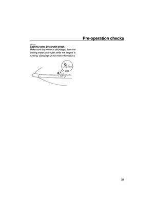
EJU33802Tool kit
A tool kit is included with this watercraft. Place
the tool kit in a waterproof bag and alwayscarry it with you whenever you use the water-
craft.
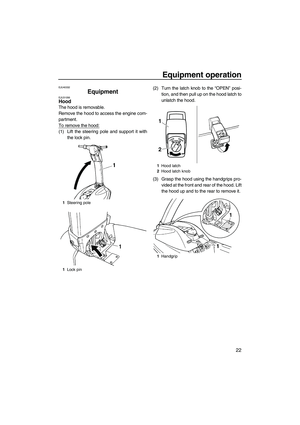
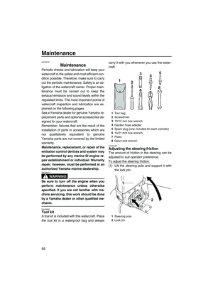
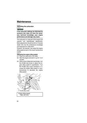
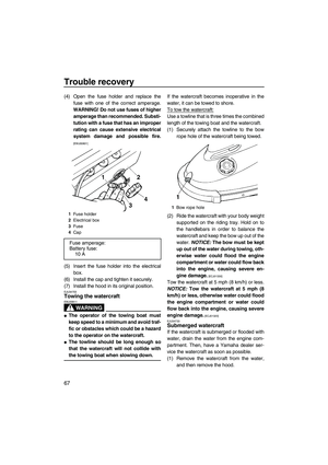
EJU34336Adjusting the steering friction
The amount of friction in the steering can be
adjusted to suit operator preference.
To adjust the steering friction:
(1) Lift the steering pole and support it with
the lock pin.
1Tool bag
2Screwdriver
310/12 mm box wrench
4Garden hose adapter
5Spark plug (one included for each cylinder)
614/21 mm box wrench
7Pliers
8Open-end wrench
1Steering pole
2Lock pin
UF2F72E0.book Page 55 Friday, May 22, 2009 5:11 PM
Page 63 of 78
 Remove the four screws, and then re-
move the handlebar cover.
(3) Turn the handlebars so that the left han-
dlebar grip is facing down.
(4) Loosen the locknut.
(5) Tighten or loose")
Maintenance
56
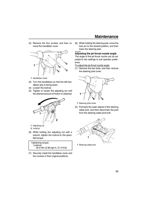
(2) Remove the four screws, and then re-
move the handlebar cover.
(3) Turn the handlebars so that the left han-
dlebar grip is facing down.
(4) Loosen the locknut.
(5) Tighten or loosen the adjusting nut until
the desired amount of friction is obtained.
(6) While holding the adjusting nut with a
wrench, tighten the locknut to the speci-
fied torque.
(7) Securely install the handlebar cover and
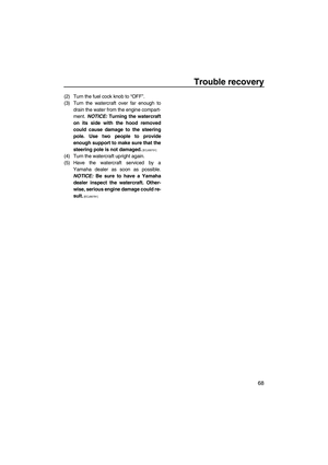
four screws in their original positions.(8) While holding the steering pole, move the
lock pin to the stowed position, and then
lower the steering pole.
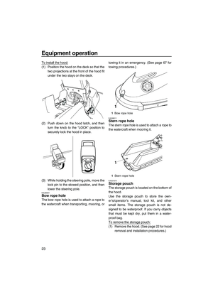
EJU31288Adjusting the jet thrust nozzle angle
The angle of the jet thrust nozzle can be ad-
justed to two settings to suit operator prefer-
ence.
To adjust the jet thrust nozzle angle:
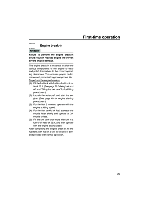
(1) Remove the two bolts, and then remove
the steering pole cover.
(2) Pull back the outer sleeve of the steering
cable joint, and then disconnect the joint
from the steering cable pivot bolt.
1Handlebar cover
1Adjusting nut
2Locknut
Tightening torque:
Locknut:
29.0 Nm (2.96 kgf-m, 21.4 ft-lb)
1
1Steering pole cover
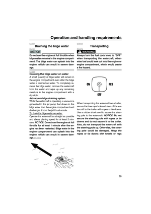
1Steering cable joint
UF2F72E0.book Page 56 Friday, May 22, 2009 5:11 PM
Page 64 of 78
Maintenance
57
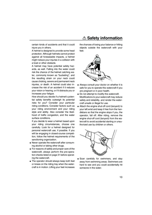
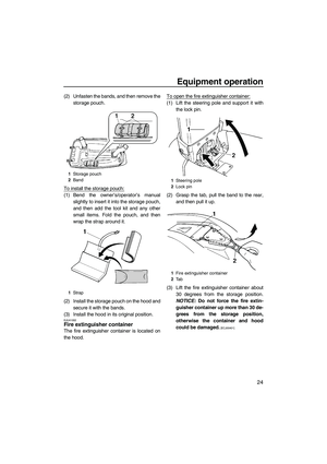
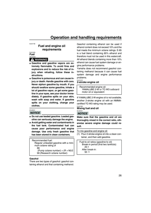
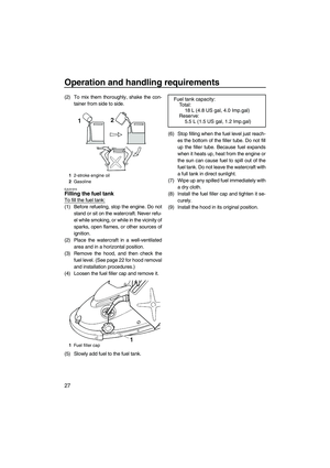
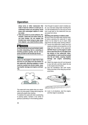
(3) Remove the steering cable pivot bolt.
(4) Select the nozzle angle, install the steer-
ing cable pivot bolt with the lock washer in
the desired position (P1 or P2) on the
steering column, and then tighten the bolt
to the specified torque.TIP:
The outermost hole in the steering column
cannot be used.
(5) Securely connect the steering cable joint
to the steering cable pivot bolt.
(6) Securely install the steering pole cover
and two bolts in their original positions.
1Steering cable pivot bolt
2Steering column
1Nozzle angles
1Nozzle angles
2Steering cable pivot bolt positions
Standard steering cable pivot bolt posi-
tion:
P2
Tightening torque:
Steering cable pivot bolt:
5.4 Nm (0.55 kgf-m, 4.0 ft-lb)
UF2F72E0.book Page 57 Friday, May 22, 2009 5:11 PM


 Remove the steering cable pivot bolt.
(4) Select the nozzle angle, install the steer-
ing cable pivot bolt with the lock washer in
the desired position (P1 or P2) on the
steering co")