Page 33 of 102

INSTRUMENT AND CONTROL FUNCTIONS
3-19
3
3. Wipe up any spilled fuel immedi-
ately. NOTICE: Immediately wipe
off spilled fuel with a clean, dry,
soft cloth, since fuel may deteri-
orate painted surfaces or plastic
parts.
[ECA10071]
4. Be sure to securely close the fuel
tank cap.
WARNING
EWA15151
Gasoline is poisonous and can
cause injury or death. Handle gaso-
line with care. Never siphon gaso-
line by mouth. If you should swallow
some gasoline or inhale a lot of gas-
oline vapor, or get some gasoline in
your eyes, see your doctor immedi-ately. If gasoline spills on your skin,
wash with soap and water. If gaso-
line spills on your clothing, change
your clothes.
EAU13320
NOTICE
ECA11400
Use only unleaded gasoline. The use
of leaded gasoline will cause severe
damage to internal engine parts,
such as the valves and piston rings,
as well as to the exhaust system.Your Yamaha engine has been de-
signed to use regular unleaded gaso-
line with a research octane number of
91 or higher. If knocking (or pinging) oc-
curs, use a gasoline of a different brandor premium unleaded fuel. Use of un-
leaded fuel will extend spark plug life
and reduce maintenance costs.
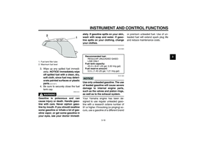
1. Fuel tank filler tube
2. Maximum fuel level
2
1
Recommended fuel:
REGULAR UNLEADED GASO-
LINE ONLY
Fuel tank capacity:
25.0 L (6.61 US gal, 5.50 Imp.gal)
Fuel reserve amount:
5.5 L (1.45 US gal, 1.21 Imp.gal)
U1CYE0E0.book Page 19 Tuesday, October 27, 2009 11:52 AM
Page 34 of 102

INSTRUMENT AND CONTROL FUNCTIONS
3-20
3
EAU39451
Fuel tank breather/overflow
hose Before operating the motorcycle:�
Check the fuel tank breather/over-
flow hose connection.
�
Check the fuel tank breather/over-
flow hose for cracks or damage,
and replace it if damaged.
�
Make sure that the end of the fuel
tank breather/overflow hose is not
blocked, and clean it if necessary.
EAU13445
Catalytic converters This vehicle is equipped with catalytic
converters in the exhaust system.
WARNING
EWA10862
The exhaust system is hot after op-
eration. To prevent a fire hazard or
burns:�
Do not park the vehicle near
possible fire hazards such as
grass or other materials that
easily burn.
�
Park the vehicle in a place
where pedestrians or children
are not likely to touch the hot
exhaust system.
�
Make sure that the exhaust sys-
tem has cooled down before do-
ing any maintenance work.
�
Do not allow the engine to idle
more than a few minutes. Long
idling can cause a build-up of
heat.
NOTICE
ECA10701
Use only unleaded gasoline. The use
of leaded gasoline will cause unre-
pairable damage to the catalytic
converter.
1. Fuel tank breather/overflow hoseU1CYE0E0.book Page 20 Tuesday, October 27, 2009 11:52 AM
Page 35 of 102

INSTRUMENT AND CONTROL FUNCTIONS
3-21
3
EAU39492
Seats Passenger seat
To remove the passenger seat1. Insert the key into the passenger
seat lock, and then turn it counter-
clockwise.
2. Lift the front of the passenger seat
and pull it forward.To install the passenger seat
1. Insert the projections on the rear of
the passenger seat into the seat
holders as shown, and then push
the front of the seat down to lock it
in place.
2. Remove the key.
Rider seat
To remove the rider seat1. Remove the passenger seat.
2. Push the rider seat lock lever, lo-
cated under the back of the rider
seat, to the left as shown, and then
pull the seat off.To install the rider seat
1. Insert the projection on the front of
the rider seat into the seat holder
as shown, and then push the rear
of the seat down to lock it in place.
1. Passenger seat lock
2. Unlock.
1. Projection
2. Seat holder
1. Rider seat lock lever
2. Rider seat
1. Projection
2. Seat holder
U1CYE0E0.book Page 21 Tuesday, October 27, 2009 11:52 AM
Page 36 of 102
INSTRUMENT AND CONTROL FUNCTIONS
3-22
32. Install the passenger seat.
TIP�
Make sure that the seats are prop-
erly secured before riding.
�
The rider seat height can be ad-
justed to change the riding posi-
tion. (See page 3-22.)
EAU39632
Adjusting the rider seat height The rider seat height can be adjusted to
one of two positions to suit the rider’s
preference.
The rider seat height was adjusted to
the lower position at delivery.
To change the rider seat height to
the high position
1. Remove the rider seat. (See page
3-21.)
2. Remove the rider seat height posi-
tion adjuster by pulling it upward.3. Move the rider seat holder cover to
the lower position as shown.
4. Install the rider seat height position
adjuster so that the “H” mark is
aligned with the match mark.1. Low position
2. High position
1. Rider seat height position adjuster
1. Rider seat holder cover
U1CYE0E0.book Page 22 Tuesday, October 27, 2009 11:52 AM
Page 37 of 102

INSTRUMENT AND CONTROL FUNCTIONS
3-23
3
5. Insert the projection on the front of
the rider seat into seat holder B as
shown.6. Align the projection on the bottom
of the rider seat with the “H” posi-
tion slot, and then push the rear of
the seat down to lock it in place as
shown.
7. Install the passenger seat.
To change the rider seat height to
the low position
1. Remove the rider seat. (See page
3-21.)
2. Remove the rider seat height posi-
tion adjuster by pulling it upward.
3. Move the rider seat holder cover to
the upper position.
4. Install the rider seat height position
adjuster so that the “L” mark is
aligned with the match mark.5. Insert the projection on the front of
the rider seat into seat holder A as
shown.
1. Rider seat height position adjuster
2.“H” mark
3. Match mark
1. Projection
2. Seat holder B (for high position)
3. Rider seat holder cover
1.“H” position slot
1. Rider seat height position adjuster
2.“L” mark
3. Match mark
1. Projection
2. Rider seat holder cover
3. Seat holder A (for low position)
1
2
3
U1CYE0E0.book Page 23 Tuesday, October 27, 2009 11:52 AM
Page 38 of 102

INSTRUMENT AND CONTROL FUNCTIONS
3-24
36. Align the projection on the bottom
of the rider seat with the “L” posi-
tion slot, and then push the rear of
the seat down to lock it in place as
shown.
7. Install the passenger seat.
TIPMake sure that the seats are properly
secured before riding.
EAU39473
Storage compartments This vehicle is equipped with two stor-
age compartments.
Storage compartment A
Storage compartment A is located un-
der the rider seat. (See page 3-21.)
When storing the Owner’s Manual or
other documents in this storage com-
partment, be sure to wrap them in a
plastic bag so that they will not get wet.
When washing the motorcycle, be
careful not to let any water enter the
storage compartment.Storage compartment B
Storage compartment B is located un-
der the passenger seat. (See page
3-21.)
This storage compartment is designed
to hold an optional genuine Yamaha
CYCLELOK. (Other locks may not fit.)
When placing a CYCLELOK in the stor-
age compartment, securely fasten it
with the straps. When the CYCLELOK
is not in the storage compartment, be
sure to secure the straps to prevent los-
ing them.
1.“L” position slot
1. Storage compartment A
1. Storage compartment B
2. Yamaha CYCLELOK (optional)
U1CYE0E0.book Page 24 Tuesday, October 27, 2009 11:52 AM
Page 39 of 102
 for storage compart-
ment A.
�
Do not exceed the load limit of 3
kg (7 lb) for storage compart-
m")
INSTRUMENT AND CONTROL FUNCTIONS
3-25
3
WARNING
EWA14420
�
Do not exceed the load limit of 1
kg (2 lb) for storage compart-
ment A.
�
Do not exceed the load limit of 3
kg (7 lb) for storage compart-
ment B.
�
Do not exceed the maximum
load of 212 kg (467 lb) for the ve-
hicle.
EAU39480
Accessory box The accessory box is located beside
the meter panel.
To open the accessory box
1. Insert the key into the main switch,
and then turn it to “ON”.
2. Push the accessory box button,
and then open the accessory box
lid.
3. Turn the key to “OFF” to preserve
the battery.
To close the accessory box
1. Fold the accessory box lid down.2. Remove the key.
NOTICE
ECA11800
Do not place heat-sensitive items in
the accessory box. The accessory
box gets extremely hot especially
when the engine is running or is hot.
WARNING
EWA11421
�
Do not exceed the load limit of
0.3 kg (0.66 lb) for the accessory
box.
�
Do not exceed the maximum
load of 212 kg (467 lb) for the ve-
hicle.
1. Accessory box lid
2. Accessory box
3. Accessory box button
U1CYE0E0.book Page 25 Tuesday, October 27, 2009 11:52 AM
Page 40 of 102

INSTRUMENT AND CONTROL FUNCTIONS
3-26
3
EAU39611
Adjusting the headlight
beams The headlight beam adjusting knobs
are used to raise or lower the height of
the headlight beams. It may be neces-
sary to adjust the headlight beams to
increase visibility and help prevent
blinding oncoming drivers when carry-
ing more or less load than usual. Obey
local laws and regulations when adjust-
ing the headlights.
To raise the headlight beams, turn the
knobs in direction (a). To lower the
headlight beams, turn the knobs in di-
rection (b).
EAU39641
Handlebar position The handlebars can be adjusted to one
of three positions to suit the rider’s pref-
erence. Have a Yamaha dealer adjust
the position of the handlebars.
EAU39621
Opening and closing the cowl-
ings The cowlings can be tilted back 30 mm
(1.18 in) for added ventilation to suit the
riding conditions.
To open a cowling
1. Remove the quick fastener
screws.
1. Headlight beam adjusting knob
1. Handlebar
1. Closed position
2. Open position
3. Cowling
U1CYE0E0.book Page 26 Tuesday, October 27, 2009 11:52 AM