2010 SUZUKI SX4 warning
[x] Cancel search: warningPage 242 of 297

7-37INSPECTION AND MAINTENANCE
80J23-03E
The main fuse, primary fuses and some of
the individual fuses are located in the
engine compartment. If the main fuse
blows, no electrical component will func-
tion. If a primary fuse blows, no electrical
component in the corresponding load
group will function. When replacing the
main fuse, a primary fuse or an individual
fuse, use a genuine SUZUKI replacement.
To remove a fuse, use the fuse puller pro-
vided in the fuse box. The amperage of
each fuse is shown in the back of the fuse
box cover.
60A243
NOTE:
Make sure that the fuse box always carries
spare fuses. MAIN FUSE / PRIMARY FUSE
(1) 80A All electric load
(2) 50APower window, Ignition,
Wiper, Starter
(3) 50ATail light, Rear defogger,
Door lock, Hazard/Horn,
Dome
(4) – Blank
(5) – Blank
(6) 15A Head light (Right) fuse
(7) 15A Head light (Left) fuse
(8) 20A Front fog light fuse
(9) – Blank
(10) 40A ABS motor fuse
(11) 30A Radiator fan fuse
(12) 30A ABS solenoid fuse
(13) 30A Starting motor fuse
(14) 50A Ignition switch fuse
(15) 30A Blower fan fuse
(16) 20A Air compressor fuse
(17) 15A Throttle motor fuse
(18) 15A Automatic transaxle fuse
(19) 15A Fuel injection fuse
(20) – Automatic transaxle relay
(21) – Air compressor relay
(22) – Fuel pump relay
(23) – Condenser fan relay
(24) – Front fog light relay
(25) – Throttle motor relay
(26) – FI MAIN relay
(27) – Starting motor relay
(28) – Radiator fan relay
(29) – Radiator fan relay 2
(30) – Radiator fan relay 3
WARNING
If the main fuse or a primary fuse
blows, be sure to have your vehicle
inspected by an authorized SUZUKI
dealer. Always use a genuine SUZUKI
replacement. Never use a substitute
such as a wire even for a temporary
fix, or extensive electrical damage
and a fire can result.
BLOWNOK
Page 244 of 297

7-39INSPECTION AND MAINTENANCE
80J23-03E
The fuses are also located under the
driver’s side of the dashboard. Remove the
fuse box cover by pulling it off. The amper-
age of each fuse is shown on the top of the
fuse box cover.
65D046
Headlight AimingSince special procedures are required, we
recommend you take your vehicle to your
SUZUKI dealer for headlight alignment. (8) 30A Wiper
(9) 10A IG1 SIG
(10) 15A Air bag
(11) 10A Anti-lock brake system
(12) – Blank
(13) 10A Stop light
(14) 20A Door lock
(15) 10A Rear fog light
(16) 10A ST SIG
(17) 15A Seat heater
(18) 10A IG 2 SIG
(19) 10A Tail light
(20) 15A Dome
(21) 30A Rear defogger
(22) 15A Horn / Hazard
(23) – Blank
(24) 30A Rear defogger
WARNING
Always be sure to replace a blown
fuse with a fuse of the correct amper-
age. Never use a substitute such as
aluminum foil or wire to replace a
blown fuse. If you replace a fuse and
the new one blows in a short period
of time, you may have a major electri-
cal problem. Have your vehicle
inspected immediately by your
SUZUKI dealer.
BLOWN OK
Page 245 of 297
7-40
INSPECTION AND MAINTENANCE
80J23-03E
Bulb ReplacementNOTE:
If it is difficult to replace headlight bulbs or
position light bulbs due to under-hood
components trust this job to your dealer.
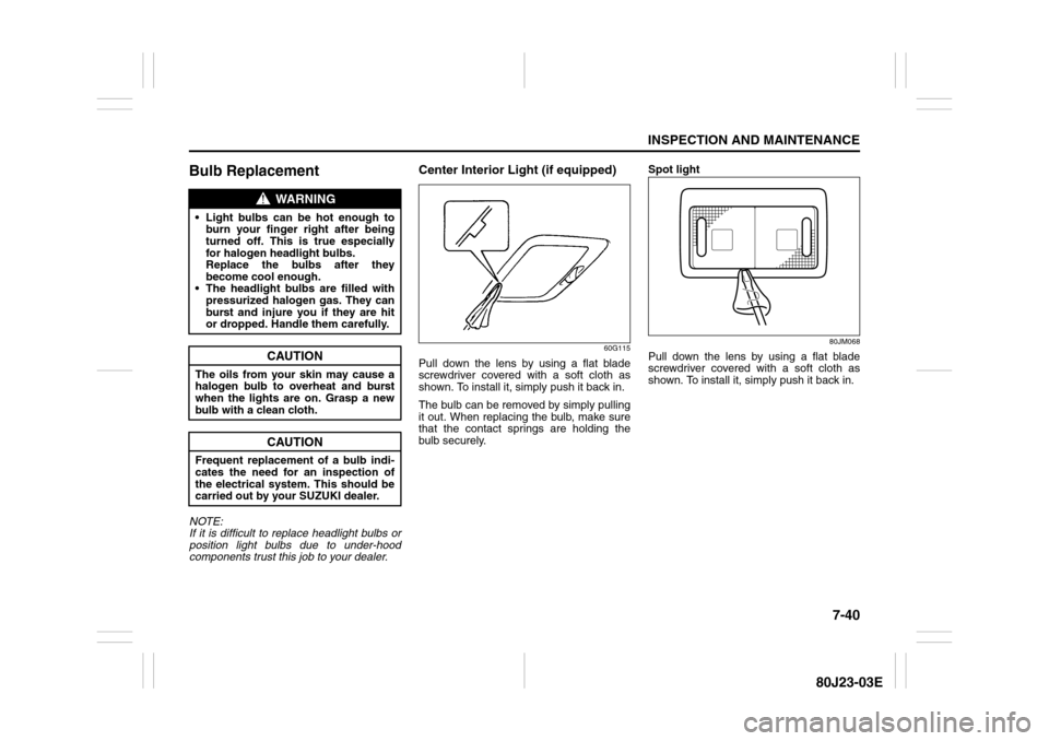
Center Interior Light (if equipped)
60G115
Pull down the lens by using a flat blade
screwdriver covered with a soft cloth as
shown. To install it, simply push it back in.
The bulb can be removed by simply pulling
it out. When replacing the bulb, make sure
that the contact springs are holding the
bulb securely.Spot light
80JM068
Pull down the lens by using a flat blade
screwdriver covered with a soft cloth as
shown. To install it, simply push it back in.
WARNING
Light bulbs can be hot enough to
burn your finger right after being
turned off. This is true especially
for halogen headlight bulbs.
Replace the bulbs after they
become cool enough.
The headlight bulbs are filled with
pressurized halogen gas. They can
burst and injure you if they are hit
or dropped. Handle them carefully.
CAUTION
The oils from your skin may cause a
halogen bulb to overheat and burst
when the lights are on. Grasp a new
bulb with a clean cloth.
CAUTION
Frequent replacement of a bulb indi-
cates the need for an inspection of
the electrical system. This should be
carried out by your SUZUKI dealer.
Page 255 of 297
7-50
INSPECTION AND MAINTENANCE
80J23-03E
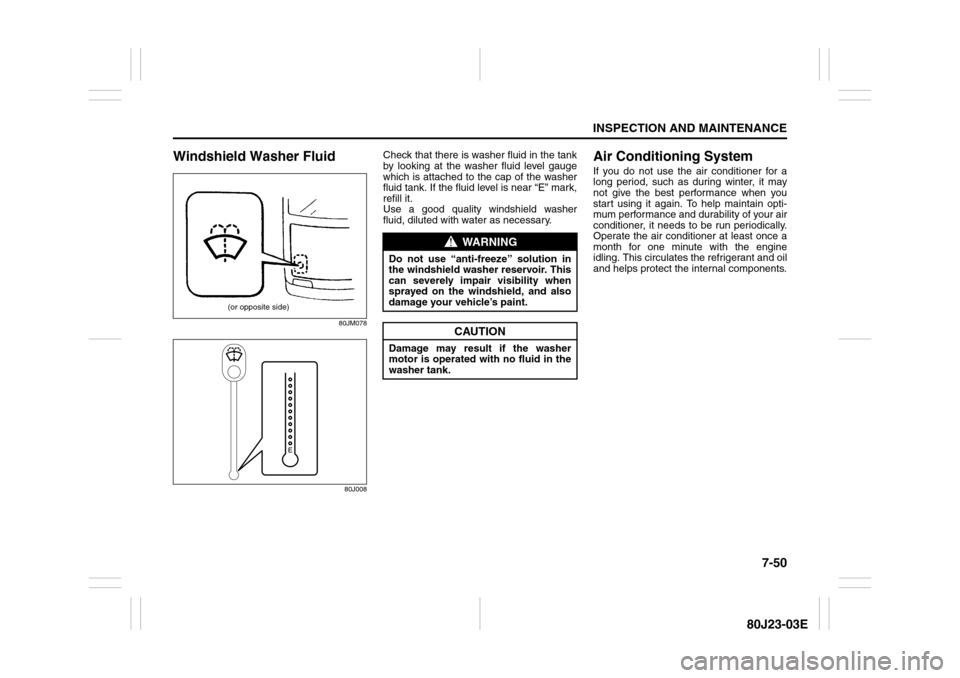
Windshield Washer Fluid
80JM078
80J008
Check that there is washer fluid in the tank
by looking at the washer fluid level gauge
which is attached to the cap of the washer
fluid tank. If the fluid level is near “E” mark,
refill it.
Use a good quality windshield washer
fluid, diluted with water as necessary.
Air Conditioning SystemIf you do not use the air conditioner for a
long period, such as during winter, it may
not give the best performance when you
start using it again. To help maintain opti-
mum performance and durability of your air
conditioner, it needs to be run periodically.
Operate the air conditioner at least once a
month for one minute with the engine
idling. This circulates the refrigerant and oil
and helps protect the internal components.
(or opposite side)
WARNING
Do not use “anti-freeze” solution in
the windshield washer reservoir. This
can severely impair visibility when
sprayed on the windshield, and also
damage your vehicle’s paint.
CAUTION
Damage may result if the washer
motor is operated with no fluid in the
washer tank.
Page 259 of 297
8-2
EMERGENCY SERVICE
80J23-03E
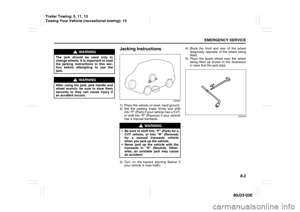
Jacking Instructions
75F062
1) Place the vehicle on level, hard ground.
2) Set the parking brake firmly and shift
into “P” (Park) if your vehicle has a CVT,
or shift into “R” (Reverse) if your vehicle
has a manual transaxle.
3) Turn on the hazard warning flasher if
your vehicle is near traffic.4) Block the front and rear of the wheel
diagonally opposite of the wheel being
lifted.
5) Place the spare wheel near the wheel
being lifted as shown in the illustration
in case that the jack slips.
54G253
WARNING
The jack should be used only to
change wheels. It is important to read
the jacking instructions in this sec-
tion before attempting to use the
jack.
WARNING
After using the jack, jack handle and
wheel wrench, be sure to stow them
securely or they can cause injury if
an accident occurs.
WARNING
Be sure to shift into “P” (Park) for a
CVT vehicle, or into “R” (Reverse)
for a manual transaxle vehicle
when you jack up the vehicle.
Never jack up the vehicle with the
transaxle in “N” (Neutral). Other-
wise, an unstable jack may cause
an accident.
Trailer Towing: 5, 11, 13
Towing Your Vehicle (recreational towing): 13
Page 260 of 297
8-3EMERGENCY SERVICE
80J23-03E
80J085
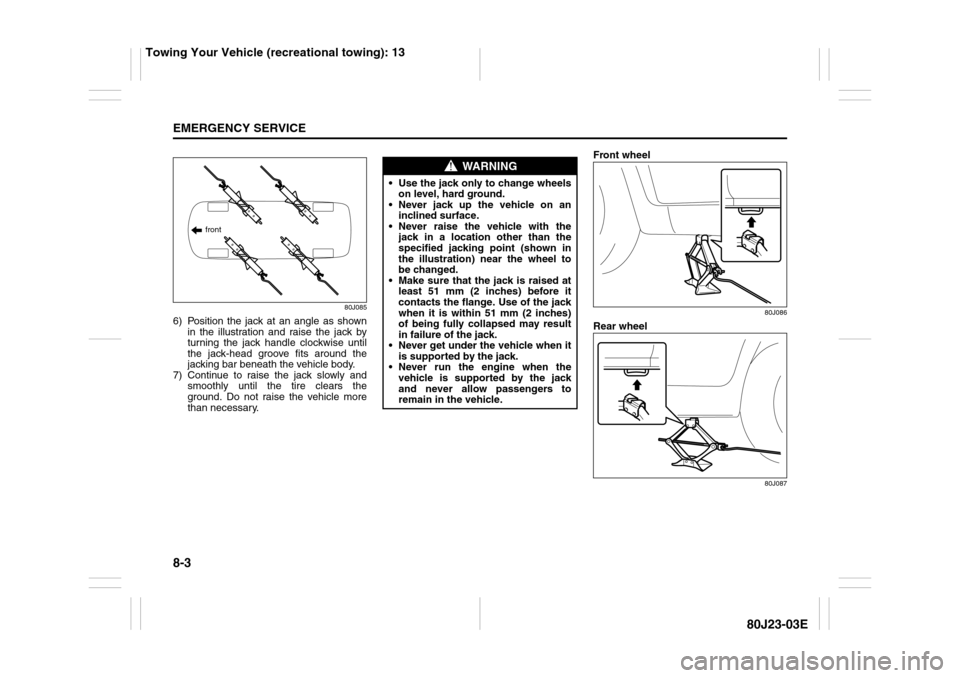
6) Position the jack at an angle as shown
in the illustration and raise the jack by
turning the jack handle clockwise until
the jack-head groove fits around the
jacking bar beneath the vehicle body.
7) Continue to raise the jack slowly and
smoothly until the tire clears the
ground. Do not raise the vehicle more
than necessary.Front wheel
80J086
Rear wheel
80J087
front
WARNING
Use the jack only to change wheels
on level, hard ground.
Never jack up the vehicle on an
inclined surface.
Never raise the vehicle with the
jack in a location other than the
specified jacking point (shown in
the illustration) near the wheel to
be changed.
Make sure that the jack is raised at
least 51 mm (2 inches) before it
contacts the flange. Use of the jack
when it is within 51 mm (2 inches)
of being fully collapsed may result
in failure of the jack.
Never get under the vehicle when it
is supported by the jack.
Never run the engine when the
vehicle is supported by the jack
and never allow passengers to
remain in the vehicle.
Towing Your Vehicle (recreational towing): 13
Page 261 of 297

8-4
EMERGENCY SERVICE
80J23-03E
Changing WheelsTo change a wheel, use the following pro-
cedure:
1) Remove the jack, tools and spare wheel
from the vehicle.
2) Loosen, but do not remove the wheel
nuts.
3) Jack up the vehicle (follow the jacking
instructions in this section).
4) Remove the wheel nuts and wheel.
5) Before installing the new wheel, clean
any mud or dirt off from the surface of
the wheel and hub with a clean cloth.
Clean the hub carefully; it may be hot
from driving.
6) Install the new wheel and replace the
wheel nuts with their cone shaped end
facing the wheel. Tighten each nut
snugly by hand until the wheel is
securely seated on the hub.
81A057
7) Lower the jack and fully tighten the nuts
in a crisscross fashion with a wrench as
shown in the illustration.
Full Wheel Cover (if equipped)
60G309
(1) or (2) Flat end tool
Your vehicle includes two tools, a wheel
brace and a jack crank, one of which has a
flat end.
Use the tool with the flat end to remove the
full wheel cap, as shown above.
54G117
When installing the cover, make sure that it
is positioned so that it does not cover or
foul the air valve.
WARNING
Be sure to shift into “P” (Park) in
CVT, or shift into “R” (Reverse) in
manual transaxle when you jack up
the vehicle.
Never jack up the vehicle with the
transaxle in “N” (Neutral). Other-
wise, unstable jack may cause an
accident.
Wheel tightening torque
85 Nm (61.5 lb-ft, 8.5 kg-m)
WARNING
Use genuine wheel nuts and tighten
them to the specified torque as soon
as possible after changing wheels.
Incorrect wheel nuts or improperly
tightened wheel nuts may come
loose or fall off, which can result in
an accident. If you do not have a
torque wrench, have the wheel nut
torque checked by an authorized
SUZUKI dealer.
EXAMPLEEXAMPLE
Towing Your Vehicle (recreational towing): 13
Page 262 of 297
8-5EMERGENCY SERVICE
80J23-03E
Jump Starting Instructions
When jump starting your vehicle, use
the following procedure:
60A269
1) Use only a 12-volt battery to jump start
your vehicle. Position the good 12-volt
battery close to your vehicle so that the
jumper cables will reach both batteries.
When using a battery installed on
another vehicle, DO NOT LET THE
VEHICLES TOUCH. Set the parking
brakes fully on both vehicles.2) Turn off all vehicle accessories, except
those necessary for safety reasons (for
example, headlights or hazard lights).
54G079
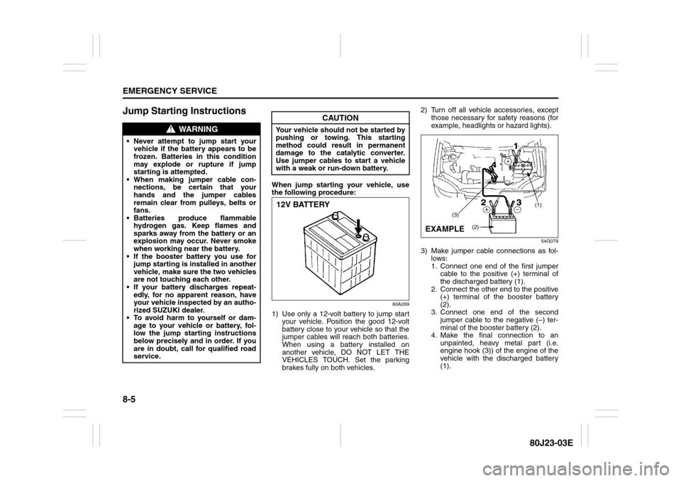
3) Make jumper cable connections as fol-
lows:
1. Connect one end of the first jumper
cable to the positive (+) terminal of
the discharged battery (1).
2. Connect the other end to the positive
(+) terminal of the booster battery
(2).
3. Connect one end of the second
jumper cable to the negative (–) ter-
minal of the booster battery (2).
4. Make the final connection to an
unpainted, heavy metal part (i.e.
engine hook (3)) of the engine of the
vehicle with the discharged battery
(1).
WARNING
Never attempt to jump start your
vehicle if the battery appears to be
frozen. Batteries in this condition
may explode or rupture if jump
starting is attempted.
When making jumper cable con-
nections, be certain that your
hands and the jumper cables
remain clear from pulleys, belts or
fans.
Batteries produce flammable
hydrogen gas. Keep flames and
sparks away from the battery or an
explosion may occur. Never smoke
when working near the battery.
If the booster battery you use for
jump starting is installed in another
vehicle, make sure the two vehicles
are not touching each other.
If your battery discharges repeat-
edly, for no apparent reason, have
your vehicle inspected by an autho-
rized SUZUKI dealer.
To avoid harm to yourself or dam-
age to your vehicle or battery, fol-
low the jump starting instructions
below precisely and in order. If you
are in doubt, call for qualified road
service.
CAUTION
Your vehicle should not be started by
pushing or towing. This starting
method could result in permanent
damage to the catalytic converter.
Use jumper cables to start a vehicle
with a weak or run-down battery.12V BATTERY
(1)
(3)
(2)
EXAMPLE