2010 SUBARU TRIBECA steering wheel
[x] Cancel search: steering wheelPage 90 of 422
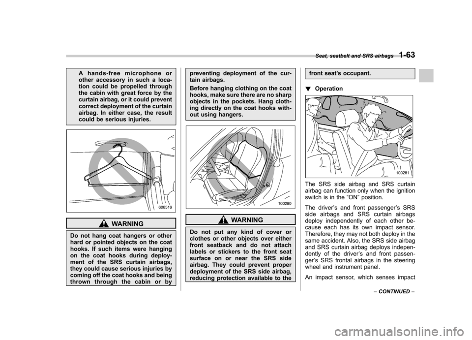
A hands-free microphone or
other accessory in such a loca-
tion could be propelled through
the cabin with great force by the
curtain airbag, or it could prevent
correct deployment of the curtain
airbag. In either case, the result
could be serious injuries.
WARNING
Do not hang coat hangers or other
hard or pointed objects on the coat
hooks. If such items were hanging
on the coat hooks during deploy-
ment of the SRS curtain airbags,
they could cause serious injuries by
coming off the coat hooks and being
thrown through the cabin or by preventing deployment of the cur-
tain airbags.
Before hanging clothing on the coat
hooks, make sure there are no sharp
objects in the pockets. Hang cloth-
ing directly on the coat hooks with-
out using hangers.WARNING
Do not put any kind of cover or
clothes or other objects over either
front seatback and do not attach
labels or stickers to the front seat
surface on or near the SRS side
airbag. They could prevent proper
deployment of the SRS side airbag,
reducing protection available to the front seat
’s occupant.
! Operation
The SRS side airbag and SRS curtain
airbag can function only when the ignition
switch is in the “ON ”position.
The driver ’s and front passenger ’s SRS
side airbags and SRS curtain airbags
deploy independently of each other be-
cause each has its own impact sensor.
Therefore, they may not both deploy in the
same accident. Also, the SRS side airbag
and SRS curtain airbag deploys indepen-
dently of the driver ’s and front passen-
ger ’s SRS frontal airbags in the steering
wheel and instrument panel.
An impact sensor, which senses impact Seat, seatbelt and SRS airbags
1-63
– CONTINUED –
Page 99 of 422
1-72Seat, seatbelt and SRS airbags
&SRS airbag system servicing
WARNING
. When discarding an airbag mod-
ule or scrapping the entire vehi-
cle damaged by a collision, con-
sult your SUBARU dealer.
. The SRS airbag has no user-
serviceable parts. Do not use
electrical test equipment on any
circuit related to the SRS airbag
system. For required servicing of
the SRS airbag, consult your
nearest SUBARU dealer. Tamper-
ing with or disconnecting the system ’s wiring could result in
accidental inflation of the SRS
airbag or could make the system
inoperative, which may result in
serious injury.
CAUTION
If you need service or repair in areas
indicated in the following list, have
the work performed by an author-
ized SUBARU dealer. The SRS air-
bag control module, impact sensors
and airbag modules are stored in
these areas. .
Under the center console
. Inside each front fender
. Steering wheel and column and
nearby areas
. Top of the dashboard on front
passenger ’s side and nearby
areas
. Each front seat and nearby area
. Inside each center pillar
. In each roof side (from the front
pillar to a point over the rear seat)
. Between the rear seat cushion
and rear wheel house on eachside
. Under the rear center seat (5-
seater models)/under the sec-
ond-row center seat (7-seatermodels)
In the event that the SRS airbag is
deployed, replacement of the system
should be performed only by an author-
ized SUBARU dealer. When the compo-
nents of the SRS airbag system are
replaced, use only genuine SUBARUparts. NOTE
In the following cases, contact your
SUBARU dealer as soon as possible. .
The front part of the vehicle was
involved in an accident in which only
the driver ’s SRS frontal airbag or both
driver ’s and front passenger ’sSRS
frontal airbags did not deploy.. The pad of the steering wheel, the
cover over the front passenger ’s SRS
frontal airbag, or either roof side (from
the front pillar to a point over the rear
seat) is scratched, cracked, or other-
wise damaged.. Center pillar, rear wheel house or
rear floor pan, or an area near these
parts, was involved in an accident in
which the SRS side airbag and SRS
curtain airbag did not deploy. . The fabric or leather of either front
seatback is cut, frayed, or otherwise damaged.. The rear part of the vehicle was
involved in an accident in which no
SRS airbag was deployed.
& Precautions against vehicle modification
WARNING
To avoid accidental activation of the
system or rendering the system
inoperative, which may result in
serious injury, no modifications
Page 100 of 422
should be made to any components
or wiring of the SRS airbag system.
This includes following modifica- tions. .Installation of custom steering
wheels
. Attachment of additional trim
materials to the dashboard
. Installation of custom seats
. Replacement of seat fabric or
leather
. Installation of additional fabric or
leather on the front seat
. Attachment of a hands-free mi-
crophone or any other accessory
to a front pillar, a center pillar, a
rear pillar, the windshield, a side
window, an assist grip, or any
other cabin surface that would be
near a deploying SRS curtainairbag.
. Installation of additional electri-
cal/electronic equipment such as
a mobile two-way radio on or
near the SRS airbag system
components and/or wiring is not
advisable. This could interfere
with proper operation of the
SRS airbag system.CAUTION
Do not perform any of the following
modifications. Such modifications
can interfere with proper operation
of the SRS airbag system. . Attachment of any equipment
(bush bar, winches, snow plow,
skid plate, etc.) other than genu-
ine SUBARU accessory parts.
. Modification of the suspension
system or front end structure.
. Installation of a tire of different
size and construction from the
tires specified on the vehicle
placard attached to the driver ’s
door pillar or specified for indivi-
dual vehicle models in this Own-er ’s Manual.
. Attachment of any equipment
(side steps or side sill protectors,
etc.) other than genuine SUBARU
accessory parts to the side body.
Always consult your SUBARU dealer if
you want to install any accessory parts on
your vehicle. Seat, seatbelt and SRS airbags
1-73
Page 131 of 422
Instruments and controlsLight control switch ........................................... 3-26
Headlights. ......................................................... 3-26
High/low beam change (dimmer) ......................... 3-27
Headlight flasher ................................................ 3-27
Daytime running light system ............................. 3-27
Turn signal lever ................................................ 3-28
Illumination brightness control ......................... 3-28
Headlight beam leveler (if equipped) ................ 3-29
For 5-seater models ........................................... 3-30
For 7-seater models ........................................... 3-31
Parking light switch ........................................... 3-32
Front fog light switch ......................................... 3-32 Wiper and washer
.............................................. 3-33
Windshield wiper and washer switches .............. 3-34
Rear window wiper and washer switch ............... 3-35
Windshield wiper deicer .................................... 3-36
Rear window defogger button .......................... 3-37
Mirrors ................................................................ 3-38
Type A inside mirror (if equipped) . ..................... 3-38
Type B inside mirror (if equipped) . ..................... 3-38
Type C inside mirror (if equipped) . ..................... 3-41
Outside mirrors ................................................. 3-42
Tilt steering wheel ............................................. 3-44
Horn .................................................................... 3-44
Page 132 of 422
Ignition switch
WARNING
. Never turn the ignition switch to
“ LOCK ”while the vehicle is
being driven or towed because
that will lock the steering wheel,
preventing steering control. And
when the engine is turned off, it
takes a much greater effort than
usual to steer.
. Before leaving the vehicle, al-
ways remove the key from the
ignition switch for safety and
never allow an unattended child
to remain in the vehicle. Failure
to follow this procedure could
result in injury to a child or
others. Children could operate
the power windows, the moon-
roof or other controls or even
make the vehicle move.
CAUTION
Do not attach a large key holder or
key case to either key. If it banged
against your knees or hands while
you were driving, it could turn the
ignition switch from the “ON ”posi- tion to the
“Acc ”or “LOCK ”posi-
tion, thereby stopping the engine.
Also, if the key is attached to a
keyholder or to a large bunch of
other keys, centrifugal force may act
on it as the vehicle moves, resulting
in unwanted turning of the ignitionswitch.
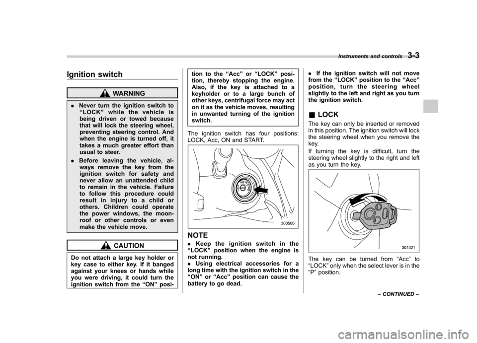
The ignition switch has four positions:
LOCK, Acc, ON and START.
NOTE . Keep the ignition switch in the
“ LOCK ”position when the engine is
not running. . Using electrical accessories for a
long time with the ignition switch in the“ ON ”or “Acc ”position can cause the
battery to go dead. .
If the ignition switch will not move
from the “LOCK ”position to the “Acc ”
position, turn the steering wheel
slightly to the left and right as you turn
the ignition switch. & LOCK
The key can only be inserted or removed
in this position. The ignition switch will lock
the steering wheel when you remove the
key.
If turning the key is difficult, turn the
steering wheel slightly to the right and left
as you turn the key.
The key can be turned from “Acc ”to
“ LOCK ”only when the select lever is in the
“ P ”position. Instruments and controls
3-3
– CONTINUED –
Page 173 of 422
3-44Instruments and controls
Tilt steering wheel
WARNING
Do not adjust the steering wheel tilt
position while driving. This may
cause loss of vehicle control and
result in personal injury.
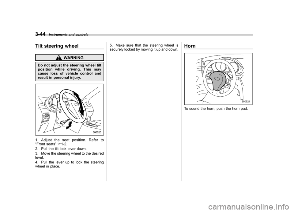
1. Adjust the seat position. Refer to “ Front seats ”F 1-2.
2. Pull the tilt lock lever down.
3. Move the steering wheel to the desired level.
4. Pull the lever up to lock the steering
wheel in place. 5. Make sure that the steering wheel is
securely locked by moving it up and down.
Horn
To sound the horn, push the horn pad.
Page 213 of 422

5-26Audio
!How to unload CDs from the player
! Ejecting a CD from the player
Of the discs loaded, you can select and
remove only one disc.
1. Use the disc select button (9) to select
the disc to be ejected.
2. Briefly press the “
”button (8). The
selected disc will be ejected. The disc
number indicator will flash at this time.
When you remove the ejected disc, the
disc number indicator will turn off.
To remove more discs in succession,
repeat Steps 1 and 2. ! Ejecting all discs from the player (all
disc ejection mode)
1. If you continue to press the “
”button
(8), the player will produce beep sound
and will enter the all disc ejection mode.
2. Remove the disc that has been
ejected. The other discs loaded will then
be ejected one after another. If you do not
remove the disc that has been ejected, the“ All disc ejection mode ”will be canceled.
NOTE . Avoid driving the vehicle with a CD
sticking out, because vibration might
make it fall out.. If you press the “
”button while the player is in all disc ejection mode,
the mode will be cancelled following
ejection of the disc that is currently
being ejected..
If you press the “CD ”button while
the player is in all disc ejection mode,
the player will draw in the discs that
have been ejected and play them. Audio control buttons
These buttons are located on the spokes
of the steering wheel. They allow the
driver to control audio functions without
taking his/her hands off the steeringwheel. &
MODE button
This button is used to select the desired
audio mode. Each time it is pressed, the
mode changes to the next one in the
following sequence.
*1: The frequency last received in the selected
Page 251 of 422
7-8Starting and operating
started. The fuel injection system auto-
matically lowers the idle speed as the
engine warms up.
While the engine is warming up, make
sure that the select lever is at the “P ” or
“ N ”position and that the parking brake is
applied. NOTE . The engine may be difficult to start
when the battery has been discon-
nected and reconnected (for mainte-
nance or other purposes). This diffi-
culty is caused by the electronically
controlled throttle ’s self-diagnosis
function. To overcome it, keep the
ignition switch in the “ON ”position
for approximately 10 seconds before
starting the engine.. To protect the engine while the
select lever is in the “P ” or “N ”
position, the engine is controlled so
that the engine speed may not become
too high even if the accelerator pedal is
depressed hard. Stopping the engine
WARNING
Do not stop the engine when the
vehicle is moving. This will cause
loss of power to the power steering
and the brake booster, making steer-
ing and braking more difficult. It
could also result in accidental acti-
vation of the “LOCK ”position on the
ignition switch, causing the steering
wheel to lock.
The ignition switch should be turned off
only when the vehicle is stopped and the
engine is idling. Remote engine start system
(dealer option)
WARNING
. Do not start the engine using the
remote start system in an en-
closed environment (e.g. closed
garage). Prolonged operation of
a motor vehicle in an enclosed
environment can cause a harmful
build-up of Carbon Monoxide.
Carbon Monoxide is harmful to
your health. Exposure to high
levels of Carbon Monoxide can
cause headaches, dizziness or in
extreme cases unconsciousness
and/or death.
. Before performing any servicing
of the vehicle, temporarily place
the remote engine start system in
service mode to prevent the
system from unexpectedly start-
ing the engine.