Page 161 of 271

Transporting children safely
160
Child safety seats in Group 1Child seats in Group 1 are for babies and small children up to 4 years of age with a
weight of between 9 and 18 kilograms. It is best for children in the lower range of this
group, to use a child seat which allows the ch ild to sit with its back to the direction of
travel. It is best for children in the uppe r range of the Group 0+, to use a child seat
which allows the child to sit page 160, fig. 141 in the direction of travel.
Child safety seats in which the child is seated with its back facing the direction of travel,
must not be used on the front passenger seat page 157, “Use of child safety seats on
the front passenger seat”.
WARNING
It is essential to always switch off th e front passenger airbag (airbags) when
attaching in exceptional circumstances a child safety seat on the front
passenger seat where the child is seated with its back facing in direction of
travel (in some countries also when the child is facing the direction of travel).
in a specialist garage
or by using the switch for the front passenger airbag* page 154,
“Switch for the front passenger airbag”.
Please comply with any differing nati onal legal regulations regarding the
use of child safety seats.
If this is not done, a child seated on the front passenger seat may suffer
severe or even fatal injuries if the front passenger airbag or airbags are
deployed.
You should have the front passenger airbag (or airbags) reactivated just as
soon as you no longer use a child safe ty seat on the front passenger seat.
Child safety seats in Group 2For children up to about 7 years of age weighing between 15 and 25 kg the optimal
solution is a child safety seat in combination with the three-point seat belt fig. 142 .
WARNING
When transporting a child on the front passenger seat, please comply with
the appropriate national regulations regard ing the use of child safety seats. If
required, the airbag has to be deactivated,
in a specialist garage
or by using the switch for the front passenger airbag* page 154,
“Switch for the front passenger airbag”.
The shoulder part of the seat belt mu st run approximately across the middle
of the shoulder and fit snugly against the chest. It must on no account run
across the neck. The lap part of the seat belt must run across the pelvis and fits
snugly; it must not run over the belly. Tighten the belt webbing over your hip if
necessary.
Please comply with any differing nati onal legal regulations regarding the
use of child safety seats.
Fig. 141 Child seat with padded table in
Group 1 installed on rear seat bench
facing the direction of travel
WARNING (continued)
Fig. 142 Child seat in Group 2 installed
on the rear seat facing the direction of
travel
s2ug.6.book Page 160 Friday, April 9, 2010 2:24 PM
Page 162 of 271

Transporting children safely161
Using the system
Safety
Driving Tips
General Maintenance
Breakdown assistance
Technical Data
Child safety seats in Group 3For children of about 7 years of age weighing between 22 and 36 kg and of a height of
less than 150 cm, the optimal solution is a ch ild safety seat (seat bolster) in combina-
tion with the three-point seat belt fig. 143 .
Children of more than 150 cm in height may use the seat belts fitted to the vehicle
without a seat bolster.
WARNING
When transporting a child on the front passenger seat, please comply with
the appropriate national regu lations regarding the use of child safety seats. If
required, the airbag has to be deactivated,
in a specialist garage
or by using the switch for the front passenger airbag* page 154,
“Switch for the front passenger airbag”.
The shoulder part of the seat belt mu st run approximately across the middle
of the shoulder and fit snugly against the chest. It must on no account run
across the neck. The lap part of the seat belt must run across the pelvis and fits
snugly; it must not run over the belly. Tighten the belt webbing over your hip if
necessary.
Please comply with any differing nati onal legal regulations regarding the
use of child safety seats.
Attaching a child seat using the “ISOFIX” systemFig. 144 Locking eyes (ISOFIX system) / the IS OFIX child seat is pushed into the mounting
funnelsThere are two fixing eyes* between the seat backrest and the seat cushion of the front
passenger seat for fixing the “ISOFIX” system child seat in place. The locking eyes on
the rear outside seats are located below th e upholstery. The places are marked with
signs with the logo “ISOFIX” - left.Install child seat– Insert the mounting funnels onto the locking eyes between the seat back-
rest and the seat cushion fig. 144 .
– Push the notched arms of the child seat in to the locking eyes in direction of arrow
, until they are heard to lock in place fig. 144 - right.
– Pull on both sides of the child seat!
One can mount a child safety seat using the “ISOFIX” system quickly, easily and reliably.
Please pay close attention to instructions from the manufa cturer of the child safety
seat when installing and removing the seat.
Child seats fitted with the “ISOFIX” system can only be mounted and fixed in a vehicle
fitted with an “ISOFIX” system when these child seats have been released for this type
of vehicle according to the ECE-R 44 standard.
You can obtain child seats with the “ISOFIX” attachment system from specialist garages
who will also installed it as well.
Complete installation instructions are enclosed with the child safety seat.
Fig. 143 Child seat in Group 3 installed
on the rear seat facing the direction of
travel
AA
AB
A1
s2ug.6.book Page 161 Friday, April 9, 2010 2:24 PM
Page 163 of 271

Transporting children safely
162WARNING
The locking eyes have just been deve loped for child safety seats which use
the “ISOFIX” system. You should therefore never attach other child safety seats,
seat belts or objects to th e locking eyes - hazard!
Ask a specialist garage whether a child seat which you bought for another
vehicle is recommended for use in your vehicle before using a child seat with
“ISOFIX” system.
Certain child seats which use the “ISO FIX” system can be attached with
standard three-point seat belts. Please pay close attention to instructions from
the manufacturer of the child safety seat when installing and removing the seat.Note
Child seats which use the “ISOFIX” system are currently available for children
weighing from 9 up to 18 kg. This correspond s to an age range of from 9 months to 4
years.
The child seats can also be fitted with the “Top Tether” system page 162.
Attaching child seat using the “Top Tether” systemThe rear exterior seats and/or the middle seat (only valid for some countries) are
equipped as standard with the attachment syst em “Top Tether” at the rear of the seat
backrest for enhancing the child safety fig. 145 .
Always perform the installation and removal of the child seat using the “Top Tether”
system as stated in the instructions from the manufacturer of the child seat.
WARNING
Attach the child seats with the “Top Tether” system only to the points
provided for this purpose fig. 145 .
On no account should you equip your vehicle, e.g. mount screws or other
anchorage points.
Pay attention to the important safety information regarding the use of child
seats.Note
Store the remaining part of the belt for the “Top Tether” system in a textile pocket,
which is located at the child seat.
Fig. 145 Rear seat: Top Tether
s2ug.6.book Page 162 Friday, April 9, 2010 2:24 PM
Page 164 of 271
*GeneralGen")
Intelligent Technology163
Using the system
Safety
Driving Tips
General Maintenance
Breakdown assistance
Technical Data
Driving TipsIntelligent TechnologyElectronic stability programme (ESP)*GeneralGeneral
The ESP aids you in maintaining control of your vehicle in situations in which the
vehicle is driving at its dynamic limits, such as entering a curve fast. The risk of skidding
is reduced and your vehicle thus offers greater driving stability depending on the
conditions of the road surface. The system operates at all speeds.
The following systems are integrated into the electronic stability programme:
Electronic Differential Lock (EDL),
Traction control system (TCS),
active driver-steering recommendation (DSR),
Antilock brake system (ABS),
Brake Assist,
Uphill Start Assist
The ESP system cannot be switched off, only the TCS system can be switched off by
pressing the button fig. 146 , the warning light
lights up. Operating principle
The ESP switches on automatically when the engine is started and then conducts a
self-test. The ESP control unit processes data from the individual systems. It also proc-
esses additional measurement data which are supplied by highly sensitive sensors: the
rotational velocity of the vehicle about its ve
rtical axis, the lateral acceleration of the
vehicle, the braking pressure and the steering angle.
The direction which the driver wishes to take is determined based on the steering
angle and the speed of the vehicle and is co nstantly compared with the actual behav-
iour of the vehicle. If differences exist, such as the vehi cle beginning to skid, the ESP will
automatically brake the appropriate wheel.
The car is stabilised again by the forces wh ich take effect when the wheel is braked.
Intervention into the brake system takes place primarily on the outer front wheel of a
vehicle which tends to oversteer (tendency for the rear of the vehicle to break away)
while occurs this is on the inner rear wh eel of a vehicle which tends to understeer
(tendency to shift out of the curve). This braking control cycle is accompanied by
noises.
During an intervention of the system, the warning light
flashes in the instrument
cluster page 34.
The ESP operates in combination with the ABS page 167, “Antilock brake system
(ABS)”. If there is a fault in the ABS system, the ESP also does not operate.
The ESP warning light lights up in the instrument cluster when there is a fault on the
ESP
page 34.WARNING
It is also not possible for the ESP to overcome the physical limits of the vehicle.
Even if a vehicle fitted with ESP you should still always adapt your style of
driving to the condition of the road surfac e and the traffic situation. This partic-
ularly applies when driving on slippery and wet roads. The increased safety
Fig. 146 ESP switch
s2ug.6.book Page 163 Friday, April 9, 2010 2:24 PM
Page 165 of 271

Intelligent Technology
164
offered must not tempt you to take greater risks than otherwise - risk of an acci-
dent!
Note
All four wheels must be fitted with the same tyres in order to achieve problem-free
operation of the ESP. Differing rolling circum ferences of the tyres can lead to an unde-
sirable reduction in the engine output.
Changes to vehicle (e.g. on engine, on th e brakes, on chassis or another combina-
tion of tyres and wheels) can influence the function of the ESP page 222, “Accesso-
ries, changes and replacement of parts”.
Electronic Differential Lock (EDL)*
The electronic differential lock prev ents an individual wheel from slip-
ping.Models fitted with ESP ar e equipped with electronic differential lock (EDL).
General
The EDL makes it much easier, and sometimes at all possible, to start off, accelerate
and climb a steep hill when the conditions of the road surface are unfavourable.
Operating principle
The EDL is activated automaticall y, that is without any action on the part of the driver.
It monitors the speeds of the driven wheels with the aid of the ABS sensors. Should
only one drive wheel begin spinning on a slippery surface there will be an appreciable
difference in the speed of the driven wheels. The EDL function brakes the slipping
wheel and the differential transmits a greate r driving force to the other driven wheel.
This control process is also accompanied by noises.
Overheating of the brakes
The EDL switches off automatica lly if unusually severe stresses exist in order to avoid
excessive heat generation in the disc brake on the wheel which is being braked. The
vehicle can continue to be driven and has the same characteristics as a vehicle not
fitted with EDL. The EDL switches on again automatically
as soon as the brake has cooled down.
EDL Off-road*
After switching on the Off-road mode page 170, EDL Off-road is activated.
EDL Off-road is matched in such a way that it assists the traction of the vehicle when
driving on an unfirm ground.
EDL is activated earlier in the Off-road mode than in the normal mode. The brake pres-
sure builts up more quickly on the slipping wheel, on one axle, as well as diagonally.
WARNING
Carefully depress the accelerator when accelerating on uniformly slippery
road surfaces, such as ice and snow. Th e driven wheels might still spin despite
the EDL and affect the stability of the vehicle - risk of an accident!
You should always adapt your style of driving to the condition of road
surface and to the traffic situation even when your vehicle is fitted with EDL.
The increased safety offered must not tempt you to take greater risks than
otherwise - risk of an accident!Note
If the ABS or ESP warning light comes on, this may also indicate a fault in the EDL.
Please have the vehicle inspected as soon as possible by a specialist garage.
Changes to vehicle (e.g. on engine, on the brakes, on chassis or another combina-
tion of tyres and wheels) can influence the function of the EDL page 222, “Accesso-
ries, changes and replacement of parts”.
WARNING (continued)
s2ug.6.book Page 164 Friday, April 9, 2010 2:24 PM
Page 166 of 271

The traction control system prevents the driven whe")
Intelligent Technology165
Using the system
Safety
Driving Tips
General Maintenance
Breakdown assistance
Technical Data
Traction control system (TCS)
The traction control system prevents the driven wheels from spinning
when accelerating.General
The TCS makes it much easier, and sometimes at all possible, to start off, accelerate and
climb a steep hill when th e conditions of the road surface are unfavourable.
Operating principle
The TCS switches on automatically when th e engine is started and then conducts a
self-test. The system monitors the speeds of the driven wheels with the aid of the ABS
sensors. If the wheels are spinning, the force transmitted to the road surface is auto-
matically adapted by reducing the engine speed. The system operates at all speeds.
The TCS operates in combination with the ABS page 167, “Antilock brake system
(ABS)”. The TCS will not function if a fault exists in the ABS system.
The TCS warning light lights up in the instru ment cluster when there is a fault on the
TCS
page 33.
During an intervention of the system, the TCS warning light
flashes in the instru-
ment cluster page 33.
Switching off
You can switch the TCS off and on again as yo u wish. On vehicles fitted with ABS, you
can switch off the TCS by pressing the button fig. 147 , on vehicles fi tted with ESP*,
you can switch off the TCS wi th the aid of the button page 163, fig. 146 . The TCS warning light lights up in the instrument cluster when the system is switched off
page 33.
The TCS should normally always be switched on. It may be good practice in certain
exceptional cases, such as when you wish to have wheel slip, to switch off the system.
Examples:
when driving with snow chains
when driving in deep snow or on a loose surface
when it is necessary to rock a vehicle when it has become stuck.
then you should switch on the TCS again.
TCS Off-road*
After switching on the Off-road mode page 170, TCS Off-road is activated.
TCS Off-road provides a more effective a cceleration of the vehicle on an unfirm
ground, as it allows higher traction be tween the slipping wheels and the ground.
The system operates when starting off or at low speeds.
WARNING
You should always adjust your style of driving to the conditions of the road
surface and the traffic situation. The increased safety offered must not tempt
you to take greater risks than otherwise - risk of an accident!
Note
All four wheels must be fitted with the same tyres in order to achieve problem-free
operation of the TCS. Differing rolling circumferences of the tyres can lead to an unde-
sirable reduction in the engine output.
Changes to vehicle (e.g. on engine, on the brakes, on chassis or another combina-
tion of tyres and wheels) can influence the function of the TCS page 222, “Accesso-
ries, changes and replacement of parts”.
Fig. 147 TCS switch
s2ug.6.book Page 165 Friday, April 9, 2010 2:24 PM
Page 167 of 271
*Vehicles with ESP and ABS are equipped with active driver-steering recommendation
(DSR).
This function indicates to the driver i")
Intelligent Technology
166
Active driver-steering recommendation (DSR)*Vehicles with ESP and ABS are equipped with active driver-steering recommendation
(DSR).
This function indicates to the driver in critical situations a steering recommendation in
order to stabilise the vehicle. The active driver-steering recommendation is activated,
for example, on the right and left vehicle si de when braking sharply on different road
surfaces.
WARNING
Even with this function the vehicle canno t steer itself! The driver is furthermore
responsible for the steering of the vehicle!BrakesWhat has a negative effect on braking efficiency?Wear-and-tear
Wear-and-tear to the brake pads is greatly dependent on the operating conditions of
the vehicle and your style of driving. Particul arly if you drive a great deal in towns and
over short distances or if you adopt a sporty style of driving, it may be necessary to
have the thickness of the brake pads inspected at a specialist garage between the
service inspections.
Wet roads or road salt
There may be a certain delay before the brakes take full effect under certain conditions
such as when driving through water, during heavy rain showers or after the vehicle has
been washed in an automatic vehicle wash , since the brake discs and brake pads may
be moist or even have a coatin g of ice on them in winter. Yo u s h o u l d d r y t h e b r a k e s a s
soon as possible by applying and releasing the brakes several times.
There also may be a certain delay before the full braking efficiency is available when
driving on roads which have been treated with road salt if you have not used the brakes
for some considerable time beforehand. The layer of salt on the brake discs and brake
pads must first be rubbed off when you apply the brakes. Corrosion
Corrosion on the brake discs and dirt on the bake pads occur if
the vehicle has been
parked for a long period and if you do not make much use of the braking system.
We recommend cleaning the brake discs by firm ly applying the brakes at a fairly high
speed if you do not make much use of the braking system or if surface corrosion is
present .
Faults in the brake surface
If you notice that the braking distance has suddenly become longer and that the brake
pedal can be depressed further, it is possib le that a brake circuit of the dual-circuit
brake system has failed. Drive, in such cases, to the nearest specialist garage without
delay in order to have the problem rectifie d. Drive at a reduced speed while on your
way to the dealer and adapt your style of driving to the higher brake pedal pressure
required.
Low brake fluid level
An insufficient level of brake fluid may result in problems in the brake system. The level
of the brake fluid is monitored electronically page 36, “Brake system ”.
WARNING
Only apply the brakes for the purpose of drying and cleaning the brake discs
if the traffic conditions permit this. Do not place any other road users in jeop-
ardy.
When retrospectively mounting a front spoiler, solid wheel hubs etc. one
must ensure that the air supply to the front wheel brakes is not reduced other-
wise the braking system could run too hot.
Allow for the fact that new brake pads do not achieve their full braking effi-
ciency until approximately 200 kilometres. New brake pads must be first “run
in” before they develop their optimal fric tion force. You can, however, compen-
sate for this slightly reduced braking fo rce by increasing the pressure on the
brake pedal. This guideline also applie s to any new brake pads installed at a
future date.
s2ug.6.book Page 166 Friday, April 9, 2010 2:24 PM
Page 168 of 271

Intelligent Technology167
Using the system
Safety
Driving Tips
General Maintenance
Breakdown assistance
Technical Data
Caution
Never allow the brakes to rub by applying sl ight pressure if you do not wish to brake
the vehicle. This causes the br akes to overheat and can also result in a longer braking
distance and excessive wear.
Before negotiating a steep downhill section, please reduce your speed, shift down
into the next lower gear (manual gearbox) or select a lower driving stage (automatic
gearbox). This enables you to make full us e of the braking power of the vehicle and
reduces the strain on the brakes. Any additional braking should be done intermittently,
not continuously.Note
The brake light flashes automatically in case of an emergency braking at speeds greater
than 60 km/h or with the intervention of the ABS, which lasts longer than 1.5 seconds.
After the speed was reduced below 10 km/h or the vehicle was stopped, the brake light
stops flashing and the hazard warning light system switches on. The hazard warning
light system is switched off automatically after accelerating or driving off again.Brake boosterThe brake booster boosts the pressure which you generate with the brake pedal. The
necessary pressure is only genera ted when the engine is running.
WARNING
Never switch off the engine before the vehicle is stationary.
The brake booster only operates when the engine is running. Greater phys-
ical effort for braking is required when en gine is switched off. Because if you do
not stop as normal, this can cause an accident and severe injuries.
Antilock brake system (ABS)ABS prevents the wheels locking when braking.General
The ABS contributes significantly to enhanc ing the active safety of your vehicle.
Compared to a vehicle not fitted with the ABS brake system, you are able to retain
optimal steering ability even during a full br ake application on a slippery road surface
because the wheels do not lock up.
In general you must not expect that the braking distance will be shorter under all
circumstances as a result of the ABS. The braking distance for example on gravel and
fresh snow, when you should anyway be driv ing slowly and cautiously, will be longer.
Operating principle
The brake pressure will be reduced on a wheel which is rotating at a speed which is too
low for the speed of the vehicle and tending to lock. This control cycle is noticeable
from a pulsating movement of the brake pedal which is accompanied by noises.
This is consciously intended to provide the driver with the information that the wheels
are tending to lock (ABS control range). You must always keep the brake pedal
depressed to enable the ABS to optimally control the brake application in this braking
range. Never interrupt the application of the brakes!
ABS Off-road*
After switching on the Off-road mode page 170, ABS Off-road is activated.
ABS Off-road increases the braking power of the vehicle on an unfirm ground, as it
keeps the wheels blocked for a longer period of time when the brake is applied while
sliding. The system is only available, if the front wheels are in the straight-ahead posi-
tion.
The system operates at speeds of up to 50 km/h.
WARNING
The ABS can also not overcome the physical limits of your vehicle. Please do
not forget this, particularly when driving on icy or wet road surfaces. If the ABS
is operating within the control range, adapt your speed immediately to the
conditions of the road surface and the traffic situation. The increased safety
s2ug.6.book Page 167 Friday, April 9, 2010 2:24 PM
 1
1 2
2 3
3 4
4 5
5 6
6 7
7 8
8 9
9 10
10 11
11 12
12 13
13 14
14 15
15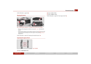 16
16 17
17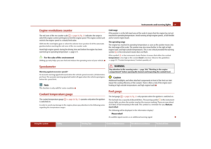 18
18 19
19 20
20 21
21 22
22 23
23 24
24 25
25 26
26 27
27 28
28 29
29 30
30 31
31 32
32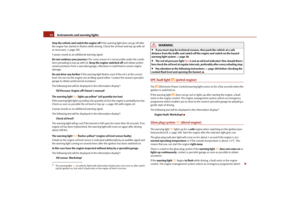 33
33 34
34 35
35 36
36 37
37 38
38 39
39 40
40 41
41 42
42 43
43 44
44 45
45 46
46 47
47 48
48 49
49 50
50 51
51 52
52 53
53 54
54 55
55 56
56 57
57 58
58 59
59 60
60 61
61 62
62 63
63 64
64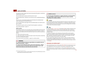 65
65 66
66 67
67 68
68 69
69 70
70 71
71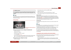 72
72 73
73 74
74 75
75 76
76 77
77 78
78 79
79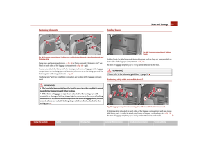 80
80 81
81 82
82 83
83 84
84 85
85 86
86 87
87 88
88 89
89 90
90 91
91 92
92 93
93 94
94 95
95 96
96 97
97 98
98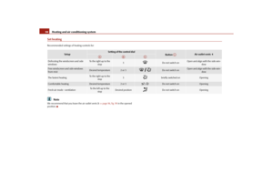 99
99 100
100 101
101 102
102 103
103 104
104 105
105 106
106 107
107 108
108 109
109 110
110 111
111 112
112 113
113 114
114 115
115 116
116 117
117 118
118 119
119 120
120 121
121 122
122 123
123 124
124 125
125 126
126 127
127 128
128 129
129 130
130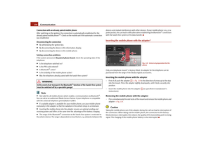 131
131 132
132 133
133 134
134 135
135 136
136 137
137 138
138 139
139 140
140 141
141 142
142 143
143 144
144 145
145 146
146 147
147 148
148 149
149 150
150 151
151 152
152 153
153 154
154 155
155 156
156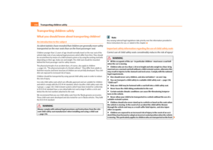 157
157 158
158 159
159 160
160 161
161 162
162 163
163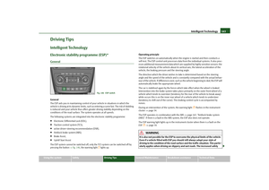 164
164 165
165 166
166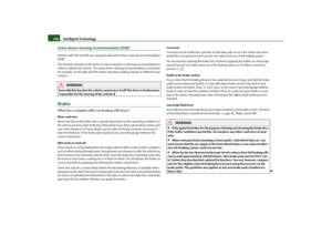 167
167 168
168 169
169 170
170 171
171 172
172 173
173 174
174 175
175 176
176 177
177 178
178 179
179 180
180 181
181 182
182 183
183 184
184 185
185 186
186 187
187 188
188 189
189 190
190 191
191 192
192 193
193 194
194 195
195 196
196 197
197 198
198 199
199 200
200 201
201 202
202 203
203 204
204 205
205 206
206 207
207 208
208 209
209 210
210 211
211 212
212 213
213 214
214 215
215 216
216 217
217 218
218 219
219 220
220 221
221 222
222 223
223 224
224 225
225 226
226 227
227 228
228 229
229 230
230 231
231 232
232 233
233 234
234 235
235 236
236 237
237 238
238 239
239 240
240 241
241 242
242 243
243 244
244 245
245 246
246 247
247 248
248 249
249 250
250 251
251 252
252 253
253 254
254 255
255 256
256 257
257 258
258 259
259 260
260 261
261 262
262 263
263 264
264 265
265 266
266 267
267 268
268 269
269 270
270